
SA3001 - Flow sensor IFM - Free user manual and instructions
Find the device manual for free SA3001 IFM in PDF.

| Product Type | Flow controller (flow sensor) |
| Brand | IFM |
| Model | SA3001 |
| Nominal pipe diameter | DN40 to DN100 |
| Number of switching outputs | 2 |
| Display | LED bar: green (current flow), yellow (output switched), red (output not switched) |
| Power supply | SELV/PELV according to EN50178, overload protection required |
| Electrical connection | 3 wires: BN (brown, L+), WH (white, output), BU (blue, L-) |
| Fluid temperature | 0 to 80 °C |
| Upstream mounting distance | Min. 5 × pipe diameter |
| Downstream mounting distance | Min. 3 × pipe diameter |
| Mounting angle on horizontal pipe | 45° |
| Installation depth | According to pipe wall thickness (flush-mounted) |
| Threshold setting | S1 and S2 adjustable in steps of 10% (display) or 2% (fine tuning) |
| Fault indication | 5 LEDs on left flash: short circuit S1; 5 LEDs on right: short circuit S2 |
| Settings lock | Press both buttons for 10 s to lock/unlock |
| Maintenance | Clean the probe with a soft cloth; use an acetic acid product for limescale deposits |
| Installation | Reserved for an electrician; disconnect power before connection |
| Fluid conditions | Laminar flow |
| Probe material | Not specified (likely stainless steel) |
Frequently Asked Questions - SA3001 IFM
User questions about SA3001 IFM
0 question about this device. Answer the ones you know or ask your own.
Ask a new question about this device
Download the instructions for your Flow sensor in PDF format for free! Find your manual SA3001 - IFM and take your electronic device back in hand. On this page are published all the documents necessary for the use of your device. SA3001 by IFM.
USER MANUAL SA3001 IFM
natural_image
Technical line drawing of a mechanical component with threaded fastener and bolted joint (no text or symbols)| Inhalt1. Bestimmungsgemäße Verwendung . . . . . . . . . . . . . . . . . . . . . . . . . . . . . . . . . . . . . . . . . . . . . . . . . . . . . . . . . . . . . . . . . . . . . . . . . . . . . . . . . . . . . . . . . . . . . . . . . . . . 2. Bedien- und Anzeigeelemente . . . . . . . . . . . . . . . . . . . . . . . . . . . . . . . . . . . . . . . . . . . . . . . . . . . . . . . . . . . . . . . . . . . . . . . . . . . . . . . . . . . . . . . . . . . . . . . . . . . Montage . . . . . . . . . . . . . . . . . . . . . . . . . . . . . . . . . . . . . . . . . . . . . . . . . . . . . . . . . . . . . . . . . . . . . . . . . . . . . . . . . . . . . . . . . . . . . . . . . . . Elektrischer Anschluß . . . . . . . . . . . . . . . . . . . . . . . . . . . . . . . . . . . . . . . . . . . . . . . . . . . . . . . . . . . . . . . . . . . . . . . . . . . . . . . . . . . . . . . . . . . . . . . . . . . Einstellen der Schaltpunkte . . . . . . . . . . . . . . . . . . . . . . . . . . . . . . . . . . . . . . . . . . . . . . . . . . . . . . . . . . . . Inbetriebnahme / Betrieb / Wartung . . . . . . . . . . . . . . . . . . . . . . . . . . . . . . . . DEUTSCH |
| Contents1. Function and features . . . . . . . . . . . . . . . . . page 102. Controls and visual indication . . . . . . . . . . . . . . . page 103. Installation . . . . . . . . . . . . . . . . . . . . . . page 114. Electrical connection . . . . . . . . . . . . . . . . . . . . . . . . . page 135. Setting the switch points . . . . . . . . . . . . . . . . . . . . . . . . . . page 146. Installation and set-up / operation / maintenance . page 15 | ENGLISH |
natural_image
Technical diagram of a mechanical assembly with rotating components (no text or symbols)Schritt 3
natural_image
Three technical line drawings of mechanical components with directional arrows indicating movement (no text or symbols)
natural_image
Technical line drawing of a mechanical component with a wrench and nut, no text or symbols present1 = BN (braun), 2 = WH (weiß), 3 = BU (blau), 4 = BK (schwarz).
natural_image
Abstract graphic with a black upward arrow and gray vertical bars (no text or symbols)bar
| Position | Value | |---|---| | 0 | 0 | | 15 | 15 | | 30 | 30 | | 45 | 45 | | 60 | 60 | | 75 | 75 | | 90 | 90 | | 105 | 105 | | 120 | 120 | | 135 | 135 | | 150 | 150 | YE (bottom segment) and GN (top segment) are highlighted in gray boxes. The arrow indicates direction of movement or transition between segments.natural_image
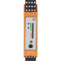
Abstract graphic with a black upward arrow and vertical bars, no text or symbols present.1. Functions and features
The flow monitor detects the flow velocity of water.
Two switching outputs provide a signal if the respectively set flow velocity has been reached.
In addition a row of LED's indicates the current flow velocity.
- For pipes with nominal widths between DN 40 ... DN 100.
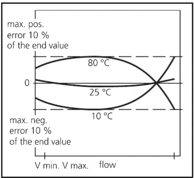
Typical measurement errors for water and different temperatures of the medium.
line
| Temperature | Value | |-------------|-----------| | 0 | 80 °C | | 25 | 25 °C | | 10 | 10 °C |2. Controls and visual indication
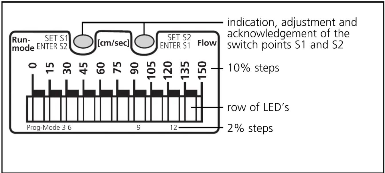
bar
| Step | Duration (cm/sec) | | :--- | :--- | | Row of LED's | 2 | | 10% steps | 0 | | 15 | 15 | | 30 | 30 | | 45 | 45 | | 60 | 60 | | 75 | 75 | | 90 | 90 | | 105 | 105 | | 120 | 120 | | 135 | 135 | | 150 | 150 | Indication, adjustment and acknowledgement of the switch points S1 and S23. Mounting
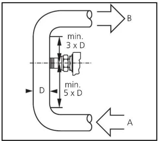
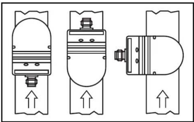
To avoid malfunction a minimum distance between the flow monitor and bends, valves, changes in cross-section or such like must be observed:
- Min. 5 x pipe diameter upstream (A),
- min. 3 x pipe diameter downstream (B).
(This information refers to laminar flow.)
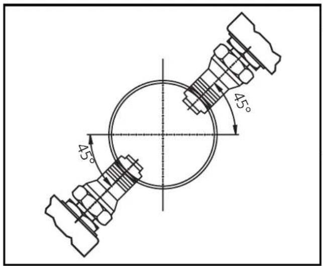
Step 1
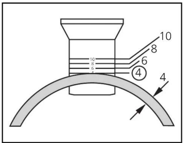
Weld the adapter into the pipe. The installation depth depends on the pipe wall thickness. The bush should be inserted so that the figure corresponding to the wall thickness is flush with the outside pipe wall and can be seen from all sides.
In the case of horizontal pipes the bush should be welded at an angle of 45irc .
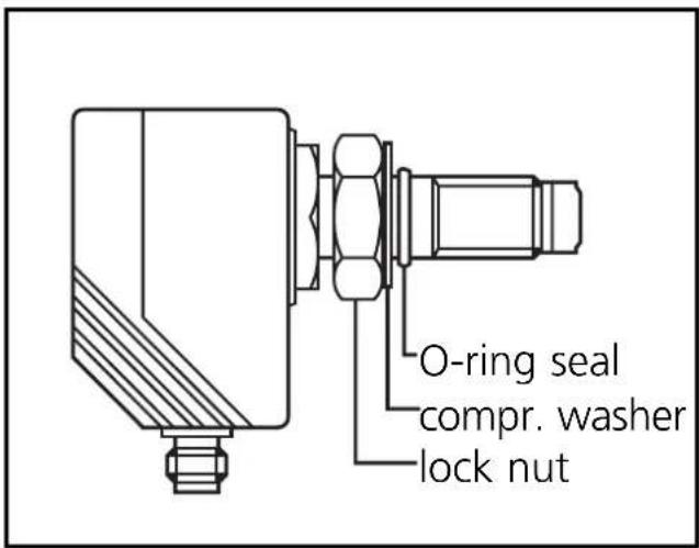
Step 2
Insert the flow monitor with lock nut, O-ring seal and compression washer into the bush and screw it in completely using the full thread.
natural_image
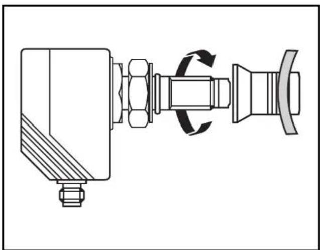
Technical line drawing of a mechanical assembly with no visible text or symbolsStep 3
Position the flow monitor (in the longitudinal pipe axis or transverse to it) and fasten the lock nut.
natural_image
Three schematic diagrams of mechanical or electrical components with upward arrows indicating flow or movement (no text or symbols)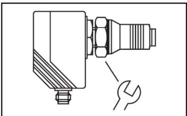
natural_image
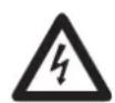
Technical line drawing of a mechanical component with a wrench and nut (no text or symbols)4. Electrical connection
The unit must only be mounted by an electrician.
The national and international regulations for the installation of electrical equipment must be observed.
Voltage supply to EN50178, SELV, PELV.
The device shall be supplied from an isolating source and protected by an overcurrent device such that the limited voltage circuit requirements in accordance with UL 508 are met.
Disconnect power before connecting the unit.
Wiring:
flowchart
graph TD
    A["pnp units npn units"] --> B["1 BN"]
    A --> C["4 BK"]
    A --> D["2 WH"]
    A --> E["3 BU"]
    B --> F["L+"]
    C --> G["S2 S1"]
    D --> H["L-"]
    E --> I["L-"]
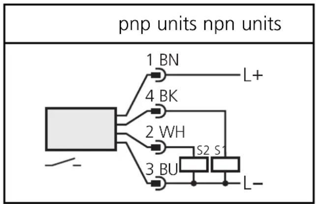
flowchart
graph TD
    A["Component"] --> B["1 BN"]
    A --> C["4 BK"]
    A --> D["2 WH"]
    A --> E["3 BU"]
    B --> F["L+"]
    C --> G["S1"]
    C --> H["S2"]
    D --> I["Ground"]
    E --> J["L-"]
Core colours of ifm sockets:
1 = BN (brown), 2 = WH (white), 3 = BU (blue), 4 = BK (black).
When the supply voltage is applied, all LEDs light and go off one after the other.* The unit is then ready for operation.
*During this time both outputs are switched (= ON).
5. Setting the switch points
Display:
 | [22HA] | lit LED = 10% value of the switching point | yellow (YE) = output switched; red (RD) = output not switched |
 | [T2KY] | flashing LED = 2% value of the switching point | |
| [22SY] | LED green = last flow value indicated | ||

natural_image
Abstract graphic with a black upward arrow and gray vertical bars (no text or symbols)Press the button and keep it pressed (here setting of S1).

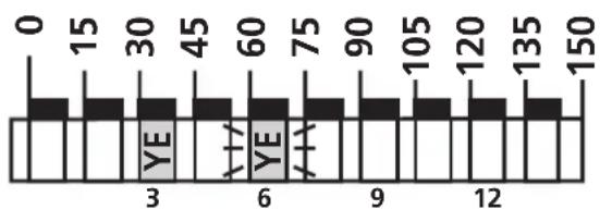
bar
| Position | Value | |---|---| | 0 | 0 | | 15 | 15 | | 30 | 30 | | 45 | 45 | | 60 | 60 | | 75 | 75 | | 90 | 90 | | 105 | 105 | | 120 | 120 | | 135 | 135 | | 150 | 150 | YE YE YEThe current switch point is indicated in steps of 2% (here: 30 + 6 = 36 cm/s ),

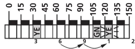
bar
| Position | Value | |---|---| | 0 | 0 | | 15 | 15 | | 30 | 30 | | 45 | 45 | | 60 | 60 | | 75 | 75 | | 90 | 90 | | 105 | 105 | | 120 | 120 | | 135 | 135 | | 150 | 150 | YE GN YE AAafter 5s the value is increased* (incremental by pressing briefly or scrolling by holding pressed).
Here: 36 - 39 - 42 cm/s
1

natural_image
Abstract graphic with a black upward arrow and gray vertical bars (no text or symbols)Press for a short time (= acknowledgement for S1).

The set value becomes effective; the unit is reset to the operating mode.
*Decrease the switch point: Let the flashing and lit LEDs move to the maximum setting value. Then the cycle starts again at the minimum setting value.
Locking/unlocking
The unit can be electronically locked to prevent unwanted adjustment of the set parameters: Press both setting buttons for 10s. Indication goes out briefly (acknowledgement of locking / unlocking). Units are delivered from the factory in the unlocked state.
6. Installation and set-up / operation / maintenance
After mounting, wiring and setting check whether the unit operates correctly.
When the supply voltage is applied, all LEDs light and go off one after the other.* The unit is then ready for operation.
*During this time both outputs are switched (= ON).
Indication in the operating mode
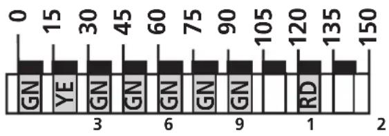 | LED's green = current flow rate (here: 90 - 105 cm/s). |
| 1st LED flashes = no flow | |
| yellow LED = switch point / output switched here: output 1 switched | |
| red LED = switch point / output not switched here: output 2 not switched |
Faults displayed during operation:
5 left LED's flashing in case of short-circuit at the switching output S1; 5 right LED's flashing in case of short-circuit at the switching output S2.
Recommended maintenance
Check the sensor tip for build-up from time to time. Clean it with a soft cloth. If necessary, build-up which adheres firmly (e.g. lime) can be removed with a common vinegar cleansing agent.
natural_image
Technical line drawing of a mechanical assembly with no visible text or symbolsPas 3
natural_image
Three technical line drawings of mechanical components with upward arrows indicating motion (no text or symbols)
natural_image
Technical line drawing of a mechanical component with a wrench and nut (no text or symbols)natural_image
Abstract graphic with a black upward arrow and gray circular elements above white vertical bars (no text or symbols)natural_image
Abstract graphic with a black upward arrow and vertical bars, no text or symbols present.

Brand : IFM
Model : SA3001
Category : Flow sensor