SR0151 - Flow sensor IFM - Free user manual and instructions
Find the device manual for free SR0151 IFM in PDF.
| Product type | Flow sensor control unit |
| Brand | IFM |
| Model | SR0151 (VS3000 series) |
| Dimensions (W x H x D) | Approx. 22.5 x 100 x 115 mm (DIN rail) |
| Weight | Approx. 150 g |
| Power supply | 24 V DC or 85 to 265 V AC (depending on version) |
| Main functions | Flow monitoring (liquid/gas), temperature monitoring, cable monitoring (break/short circuit), relay output, threshold adjustment |
| Maintenance and cleaning | No maintenance required under normal operation; periodic relay contact check recommended |
| Safety | IP20, protection class II, installation by qualified electrician, installation in electrical cabinet |
| Spare parts and reparability | Pluggable terminals available (ref. E40171/E40173); repair only by manufacturer |
| General information | For SFxxxx flow sensors; DIN rail mounting; not approved for personnel safety; detailed documentation at ifm.com |
Frequently Asked Questions - SR0151 IFM
User questions about SR0151 IFM
0 question about this device. Answer the ones you know or ask your own.
Ask a new question about this device
Download the instructions for your Flow sensor in PDF format for free! Find your manual SR0151 - IFM and take your electronic device back in hand. On this page are published all the documents necessary for the use of your device. SR0151 by IFM.
USER MANUAL SR0151 IFM
Operating instructions
Evaluation system for flow sensors
Notice utilisateurs
BN = braun, BU = blau, BK = schwarz, WH = weiß, GY = grau
1 Preliminary note 2
2 Safety instructions 3
3 Function and features 4
4 Mounting 4
4.1 Mounting of the sensors 5
5 Electrical connection 5
5.1 Terminal connection 6
5.2 Power supply (Power) 6
5.3 Connection of sensors 7
5.4Relay outputs 7
6 Settings 7
7 Operation 8
7.1 Function diagram flow monitoring 8
8 Maintenance, repair, disposal 9
9 Technical data and scale drawing 9
1 Preliminary note
The operating instructions apply to all control monitors of type VS3000 for 35mm DIN rail mounting. The only difference between the individual units is the type of supply voltage which is indicated on the type label of the unit. 2 versions are available: 24 V DC and 85 to 265 V AC.
The operating instructions are part of the unit. They contain information about the correct handling of the product. Read them before use to get familiar with operating conditions, mounting and operation. Adhere to the safety instructions. The operating instructions are made for authorised persons according to the EMC and low voltage guidelines.
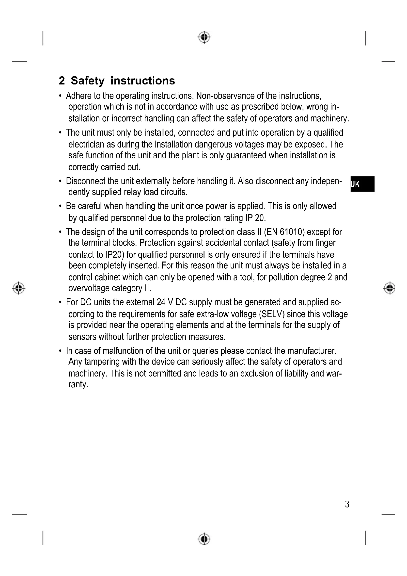
2 Safety instructions
- Adhere to the operating instructions. Non-observance of the instructions, operation which is not in accordance with use as prescribed below, wrong installation or incorrect handling can affect the safety of operators and machinery.
- The unit must only be installed, connected and put into operation by a qualified electrician as during the installation dangerous voltages may be exposed. The safe function of the unit and the plant is only guaranteed when installation is correctly carried out.
- Disconnect the unit externally before handling it. Also disconnect any independently supplied relay load circuits.
- Be careful when handling the unit once power is applied. This is only allowed by qualified personnel due to the protection rating IP 20.
- The design of the unit corresponds to protection class II (EN 61010) except for the terminal blocks. Protection against accidental contact (safety from finger contact to IP20) for qualified personnel is only ensured if the terminals have been completely inserted. For this reason the unit must always be installed in a control cabinet which can only be opened with a tool, for pollution degree 2 and overvoltage category II.
- For DC units the external 24 V DC supply must be generated and supplied according to the requirements for safe extra-low voltage (SELV) since this voltage is provided near the operating elements and at the terminals for the supply of sensors without further protection measures.
- In case of malfunction of the unit or queries please contact the manufacturer. Any tampering with the device can seriously affect the safety of operators and machinery. This is not permitted and leads to an exclusion of liability and warranty.
3 Function and features
The evaluation system VS3000 is designed to work with flow sensors of the type SFxxxx. It evaluates the signals from the sensors and signals whether there is a preset flow rate or not:
- Flow above the preset value / output relay is energised.
- Flow below the preset value / output relay is de-energised.
- Flows of either liquids or gases can be monitored.
- Wire break monitoring: in the case of an open-circuit or short-circuit the monitoring relay is de-energised, the red LED (WIRE BREAK/RELAY) signals a fault.
- Temperature monitoring: relay is energised when temperature is exceeded, the red LED (TEMP/RELAY) signals a fault.

The unit is not approved for safety tasks in the field of safety of persons.
4 Mounting
- Install the unit in a control cabinet which can only be opened with a tool, for pollution degree 2 and overvoltage category II, to guarantee protection against accidental contact with dangerous contact voltages and against atmospheric influences. The control cabinet should be installed in accordance with local and national rules and regulations.
- Mount the unit on a DIN rail Once mounted leave enough space between the unit and the top and bottom of the control cabinet (to enable clear space for convection cooling).

When several units are mounted side by side the internal heating of all units has to be considered. The ambient temperature for the individual unit must not exceed the permissible value of +60^ .
In this case adhere to the distances between the units. The following applies to identical VS3000 units: distance = at least 5 mm.
For units from other companies the permissible distance is to be determined by measurements.
- Prevent the penetration of conductive or other dirt into the housing or wiring.
4.1 Mounting of the sensors
Adhere to the mounting instructions of the manufacturer.
5 Electrical connection

The unit must only be connected by an electrician.
The national and international regulations for the installation of electrical equipment must be observed.
Avoid contact with voltages.
Disconnect the plant from power before wiring.
-
Check if the relays are connected to voltages of external power supplies.
-
In order to avoid malfunction caused by interference, lay the sensor cable separately from the load cable. Max. length of the sensor cable: 100m.
-
Connection by means of Combicon connectors (fitted). Combicon connectors are also available as accessories:
-
connector with cage clamps (order no. E40171),
- connector with screw terminals (order no. E40173).
5.1 Terminal connection
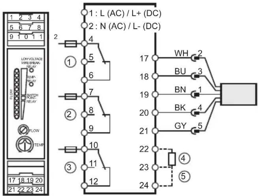
1: flow monitoring
2: wire break monitoring
3: temperature monitoring
4: power-on delay time
5: selection liquid / gas
Core colours for flow sensors of the type SFxxxx:
BN = brown, BU = blue, BK = black, WH = white, GY = grey
5.2 Power supply (Power)
Terminal 1: L (AC unit) / L+ (DC unit).
Terminal 2: N (AC unit) / L- (DC unit).
- For DC units the supply voltage must be protected externally (max. 2A).
- The terminals of the DC supply are directly linked with the terminals of the sensor supply. This is why the SELV criteria must be adhered to for DC supply (protective low voltage, circuit galvanically separated from other circuits, not earthed).
-
If the DC circuit is to be earthed (e.g. because of national regulations), the PELV criteria have to be adhered to (protective low voltage, circuit galvanically separated from other circuits).
-
If the unit is supplied with AC voltage, the low voltage supply for the sensors meets the SELV criteria.
5.3 Connection of sensors
Please also adhere to the SELV criteria for the sensor connection so that there is no dangerous contact voltage at the sensor which can enter the unit!
5.4 Relay outputs
The voltage between the different output circuits (terminals 4, 5, 6 - terminals 7, 8, 9 - terminals 10, 11, 12) must not exceed the permissible maximum value of 300V AC.
Insert a miniature fuse according to IEC60127-2 Sheet 1 (≤ 5 A fast acting).
6 Settings
| 4 5 LOW/VICE WIRE RELAY FLOW SWITCH PONF RELAY FLOW TEMP 1 2 3 | 1 | Bank of LED's - red LED lit: flow below the switch point - yellow LED lit: relay is energised, flow has reached the switch point - green LED lit: flow above the switch point |
| 2 | Potentiometer (switch point flow) | |
| 3 | Potentiometer (switch point temperature) | |
| 4 | Red LED (WIRE BREAK/RELAY): lights in case of wire break or short circuit of the sensor wires | |
| 5 | Red LED (TEMP/RELAY): lights if the set temperature is exceeded |
-
Selection of the monitored medium: Factory setting: Monitoring of liquids. For monitoring of gases: Link terminals 23 / 24.
-
Setting of the power-on delay time t1:
Factory setting: t1 = 10 s. To define other times: Connect an external resistor (R) between the terminals 22 and 23.
| t1 [s] | 15 20 | 25 30 | 35 40 | 45 50 | 55 60 | 65 70 | 75 80 | ||||||
| R [kΩ] | 10 18 | 27 39 | 47 56 | 68 82 | 100 | 120 | 150 | 180 | 220 | 270 |
- Apply the operating voltage. After the power-on delay time has elapsed, the unit is ready for operation, (during this time the output relay for flow monitoring is energised).
- Set the preset flow and keep it constant. Turn the setting potentiometer (2) until a green LED lights. The farther the green LED lit is away from the yellow LED, the safer is the adjustment (excess gain for flow or temperature fluctuations).
- Set the setting potentiometer for the temperature monitoring (3) to the requested limit temperature.
7 Operation
After mounting, wiring and setting check whether the unit operates correctly.
For units with monitoring of the sensor cable: In the case of wire break or short circuit the relay „wire monitoring“ is de-energised and the red LED lights. After rectification of the fault the control monitor is again ready for operation.
7.1 Function diagram flow monitoring
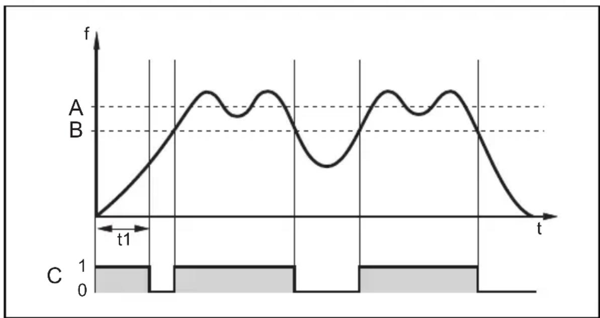
A = preset flow; B = switch point; C = output relay
t1 = power-on delay time
8 Maintenance, repair, disposal
In case of correct use no maintenance measures are necessary.
Depending on the switching rate to be expected and the load to be switched, we recommend testing the relay contacts.
Only the manufacturer is allowed to repair the unit.
After use dispose of the unit in an environmentally friendly way according to the valid national regulations.
9 Technical data and scale drawing
Technical data and scale drawing at www.ifm.com Data sheet search Enter the article number.
Contenu
BN = brun, BU = bleu, BK = noir, WH = blanc, GY = gris
5.2 Alimentation
Borne 1:L (appareil AC)/L+ (appareil DC),
borne 2: N (appareil AC) / L- (appareil DC).