KW5001 - Capacitive proximity sensor IFM - Free user manual and instructions
Find the device manual for free KW5001 IFM in PDF.
User questions about KW5001 IFM
0 question about this device. Answer the ones you know or ask your own.
Ask a new question about this device
Download the instructions for your Capacitive proximity sensor in PDF format for free! Find your manual KW5001 - IFM and take your electronic device back in hand. On this page are published all the documents necessary for the use of your device. KW5001 by IFM.
USER MANUAL KW5001 IFM
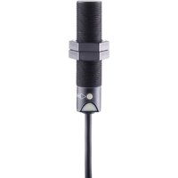
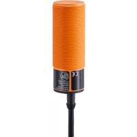
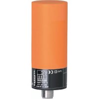
Capacitive proximity switch KW
natural_image
Top-down schematic of a rectangular device with four slots and two connectors (no text or symbols)Inhalt Seite
natural_image
Cross-sectional diagram of a mechanical or electrical component with hatched fill (no text or symbols)Adernfarben: BN = braun, BU = blau, BK = schwarz, WH = weiß
- Function and features 10
- Installation 11
- Electrical connection 11
- Operation 12
- Programming 13
- Set-up / operation 17
- Wiring diagram 27
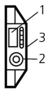
text_image
1 2 3
text_image
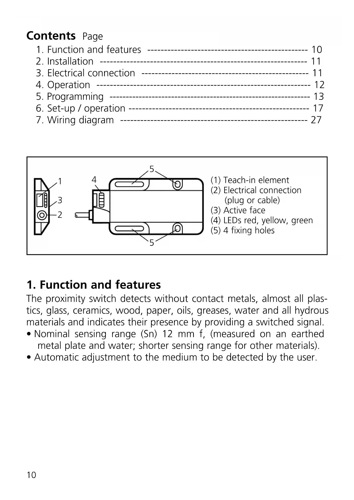
4 5 5(1) Teach-in element
(2) Electrical connection (plug or cable)
(3) Active face
(4) LEDs red, yellow, green
(5) 4 fixing holes
1. Function and features
The proximity switch detects without contact metals, almost all plastics, glass, ceramics, wood, paper, oils, greases, water and all hydrous materials and indicates their presence by providing a switched signal.
- Nominal sensing range (Sn) 12 mm f, (measured on an earthed metal plate and water; shorter sensing range for other materials).
• Automatic adjustment to the medium to be detected by the user.
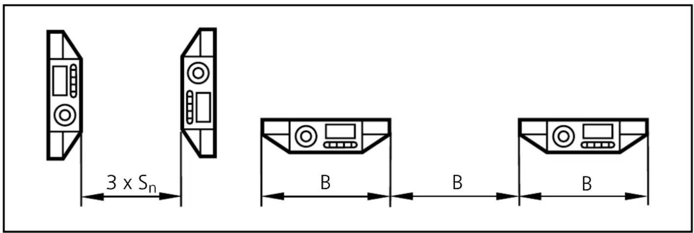
2. Installation
Mount the unit by means of the fixing holes. For flush mount see the following drawing:

natural_image
Cross-sectional diagram of a mechanical or electrical component with hatched fill (no text or symbols)Minimum distance when several switches of the same type are mounted:
3. Electrical connection
Disconnect power before connecting the unit (see page 27 or type label).
Core colours: BN = brown, BU = blue, BK = black, WH = white
Function check output / programming wire pin 2/WH
This is a bidirectional wire.
- When used as function check output output signals can be evaluated by the unit.
- When used as programming wire operations can be carried out.
Signals on the function check output
| State Signal | |
| Function check The function check output is conductive. | |
| Adjustment error The output changes between conductive and blocked state at 7 Hz. | |
Connection programming wire
| Type of unit Triggering an operation | |
| PNP To activate | the function the wire is connected to "L+". |
| NPN To activate | the function the wire is connected to "L-". |
4. Operation
The sensor is operated via the inductive teach-in element or the programming wire.
Teach-in element
If you touch the marked field with a metal object (e.g. screw-driver), the teach-in element is activated.
If you remove the object from this field, the teach-in element is deactivated.
In the following text "actuation" means a simple operation of contact to activate and deactivate again the teach-in element without special time conditions.

text_image
contact area of the teach-in elementOperation via the programming wire (pin 2/WH)
You can carry out the following operations via the programming wire. A signal on this input corresponds to the actuation of the teach-in element.

Programming via the teach-in element has priority over the programming wire (pin 2/WH). New programming or one in process via the programming wire is blocked by actuating the teach-in element.
5. Programming
Setting the switching threshold for stationary objects
The unit detects the states "object" and "no object" and adjusts the internal switching threshold electronically.
| 1 | Bring the unit into the adjustment mode.Actuate the teach-in 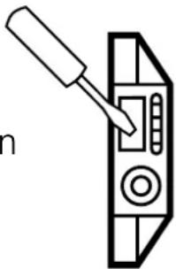 element for 2s. element for 2s. |
| The LEDs yellow and green flash alternately (1 Hz). The unit is in the adjustment mode. |
| 2 | Place the object in the sensing zone of the unit.Actuate the teach-  element briefly. element briefly. |
| The LEDs yellow and green go out briefly and then quickly flash alternately (2 Hz). The LED red is lit. |
| 3 | Remove the object or increase the distance between object and unit until the red LED goes out.Actuate the teach-  element briefly. element briefly. |
| The LEDs yellow and green go out briefly, then the LED green is lit.The LED yellow indicates the current switching state.The unit is in the operating mode. |
You can also proceed in reverse order for steps 2 and 3:
First set without object, then bring the object into the sensing zone until the red LED goes out.
Setting the switching threshold for moving objects
If fast regular operations (e.g. counting operations) are to be detected at a frequency of over 2 Hz (up to max. 40 Hz), the unit can set the switching threshold by means of a maximum-minimum detection of moving objects.
| 1 | Mount the unit so that the object to be detected is in the sensing zone of the active face. The object is moving (faster than 2 Hz).Actuate the teach-ir element for 2s.  |
| The LEDs yellow and green flash alternately (1 Hz). |
| 2 | The object continues to move (faster than 2 Hz).Actuate the teach-irelement briefly.  |
| The LEDs yellow and green flash alternately (2 Hz),in addition the red LED is lit continuously. | |
| 3 | The object continues to move (faster than 2 Hz).Actuate the teach-irelement briefly.  |
| The LEDs yellow, green and red go out, then the LED green is lit.The LED yellow and the switching output should now follow themovement of the object. |
Error message
If adjustment is not possible, the red LED flashes quickly at about 7 Hz after the adjustment attempt (adjustment error). To delete this error message actuate the teach-in element once or disconnect and connect power again. The adjustment positions successfully read so far remain unchanged.
Possible causes of an adjustment error:
- For a stationary object
The signal difference between adjustment with object and adjustment without object is too small.
Help: Reduce the distance between unit and object and repeat the adjustment.
- For a moving object
a) The frequency is too low and thus the detection of movement is not active.
Help: Increase the frequency or adjust with a stationary object b) The frequency is too high and thus the signal difference is too small.
Help: Reduce the distance between unit and object or decrease the frequency. Repeat the adjustment.
Other error types (these errors are no adjustment errors):
• Electronic fault or sensing zone of the unit damaged.
- Internal fault (can only be deleted by disconnecting and connecting power again, hardware reset).
Locking
The stored adjustment values can be protected against unauthorised programming as follows (output state "not locked"):
| Actuate the teach-in element for min. 10s | 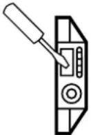 |  | After about 2s the green and yellow LED start to flash at 1 Hz alternately. After about 10s the green LED goes out, the unit is locked. |
When the teach-in element is deactivated the unit is locked and all programming functions are blocked. The unit returns to the operating mode (LED green is lit).
Unlocking
If this operation starts from the locked state, the green LED does not react at first to avoid any hint to a hidden function.
If you want to release the locking, proceed as follows:
| Actuate the teach-in element for min. 10s. |  |  | After 10s the LEDs go out. The unit is then unlocked and the LEDs indicate the current operating state. |
When the teach-in element is deactivated the unit is unlocked and all programming functions are released again. The unit returns to the operating mode.
6. Set-up / operation
Check the safe functioning of the unit.
Indication by LEDs and function check output.
| LED green | ON = the unit is ready for operation. |
| LED yellow | ON = the output is switched. |
| LED red + function check output | ON = function check. |
| LED red + function check output | Flashes or 7 Hz signal of the function check output = internal fault, adjustment error. |
| LEDs yellow + red | Flash at the same frequency (2 Hz) = output shorted. |
The operation of the proximity switch is maintenance-free. For a correct function ensure:
- The active face and the open space should be kept free of deposits and foreign bodies, particularly for mounting with the sensing face showing upwards.
The red LED indicates no malfunction of the unit, it indicates that the internal sensor signal is near the switching threshold.
2 cases can be distinguished:
- Normal operation/safe operation
The red LED is lit temporarily during the change between "object" and "no object".
- Warning of possible malfunction
If the red LED is lit continuously, the operating conditions are no longer optimum.
For example a change of the sensing range caused by deposits of dirt can be detected.
You can take preventive measures to avoid a malfunction. For example readjust or clean the unit.