
KI5209 - Capacitive proximity sensor IFM - Free user manual and instructions
Find the device manual for free KI5209 IFM in PDF.
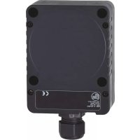
| Product type | Capacitive proximity sensor |
| Brand | IFM |
| Model | KI5209 |
| Power supply | 10-30 V DC (depending on version) |
| Nominal range | Adjustable via potentiometer (see datasheet) |
| Output | Programmable NO/NC, PNP/NPN |
| Status indication | Yellow LED (output active) |
| Detected materials | Metals, plastics, glass, ceramic, wood, paper, oils, greases, water, aqueous fluids |
| Mounting | Flush or non-flush depending on type |
| Connection | Connector (type KI) |
| Programming | Via shunt in connector or via wiring |
| Protection | Pulsed short-circuit protection |
| Operating temperature | -25 to 70 °C (estimated) |
| Ingress protection | IP67 (estimated) |
| Maintenance | No maintenance required; keep the active face clean |
| Repairability | Not repairable |
| Disposal | Environmentally friendly disposal according to national regulations |
Frequently Asked Questions - KI5209 IFM
User questions about KI5209 IFM
0 question about this device. Answer the ones you know or ask your own.
Ask a new question about this device
Download the instructions for your Capacitive proximity sensor in PDF format for free! Find your manual KI5209 - IFM and take your electronic device back in hand. On this page are published all the documents necessary for the use of your device. KI5209 by IFM.
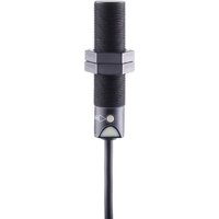
USER MANUAL KI5209 IFM
Operating instructions
Capacitive sensors
natural_image
Simple line drawing of a rectangular object with a small protrusion on the left side (no text or symbols)
Inhalt
natural_image
Pure electrical circuit lines without any symbols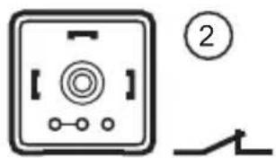


LED1:
Potentiometer2:
Einstellungen6
Schaltabstand6.1
1 Safety instructions ....3
2 Functions and features ....4
3 Installation....4
3.1 Notes on flush and non-flush installation ....4
4 Electrical connection ....5
4.1 Wiring ....5
4.2 Programming 6
4.3 Type KI (with connector) 6
4.3.1 Programming via the link in the connector ....6
4.3.2 Programming via wiring (KGE - DC PNP/NPN) 6
4.4 Type KDE - two-wire technology 6
4.4.1 Programming via wiring (KDE - AC/DC PNP/NPN) 6
4.5 Type KDE - three-wire technology ....7
4.5.1 Programming via wiring (KDE - DC PNP/NPN) 7
4.6 Type KIE / KGE 8
4.6.1 Programming via the wire link 8
5 Operating and display elements ....8
5.1 Example type KB 8
6 Settings....9
6.1 Sensing range ....9
7 Operation....9
8 Maintenance, repair, disposal ....9
9 Definitions....9
Preliminary note
An instruction is indicated by "▶":•
Example: ▶ Check whether the unit operates correctly.
A reaction to the action is indicated by ">":•
Example: > Yellow LED lights.

Important note
Non-compliance can result in malfunctions or interference.

Information
Supplementary note.

Safety instructions1
Please read the product description prior to set-up of the unit. Ensure that the product is suitable for your application without any restrictions.
The unit conforms to the relevant regulations and EC directives.
Improper or non-intended use may lead to malfunctions of the unit or to • unwanted effects in your application.
That is why installation, electrical connection, set-up, operation and maintenance of the unit must only be carried out by qualified personnel authorised by the machine operator.
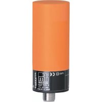
Functions and features2
The capacitive sensor detects without contact metals, almost all plastics, glass, ceramics, wood, paper, oils, greases, water and all hydrous materials and indicates their presence by providing a switched signal.
Installation3
Notes on flush and non-flush installation3.1
In case of flush installation of non-flush units the sensor properties change and the sensor can remain permanently switched (loss of function).
Observe the free space around the sensing face.
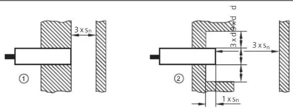
flush1:
non-fl ush2:
Sn : nominal sensing range (see data sheet)
d: unit diameter
Observe the minimum distances when installing several sensors of the same type.
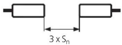
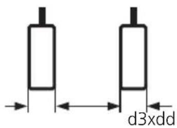
Sn : nominal sensing range (see data sheet)
d: unit diameter
Observe the minimum distance when installing the type KD ▶
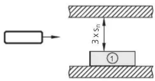
1: sensor type KD (only non-flush installation)
UK

The distances need to be determined by the user in his application.
Electrical connection4

The unit must be connected by a qualified electrician. The national and international regulations for the installation of electrical equipment must be adhered to.
Disconnect power.
Connect the sensor according to the indications on the type label.
Note: use a miniature fuse according to the technical data sheet, if specified. Recommendation: check the safe functioning of the unit after a short circuit.
Wiring 4.1
2-wire
technology
3-wire
techni
miniature fuse (for AC units)1:
negative switching2:
positive switching3:
Programming4.2
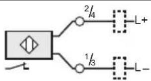
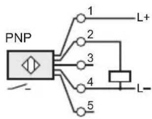
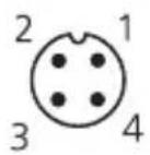
Type KI (with connector)4.3
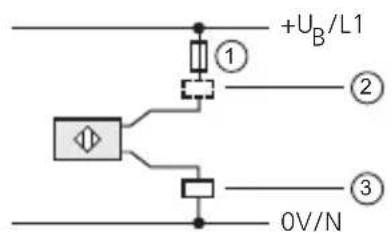
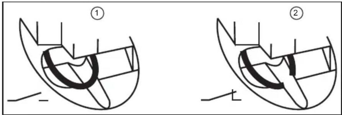
Programming via the link in the connector4.3.1
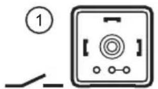
natural_image
Simple line drawing of a device with a switch and circular button (no text or symbols)
programmed as normally open (factory setting)1:
programmed as normally closed2:
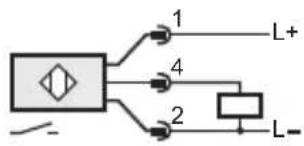
Programming via wiring (KGE - DC PNP/NPN)4.3.2
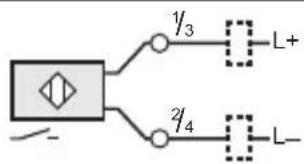
flowchart
graph TD
    A["Input"] --> B["γ₃"]
    A --> C["γ₄"]
    B --> D["L+"]
    C --> E["L-"]
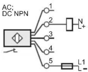
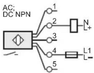
Type KDE - two-wire technology4.4
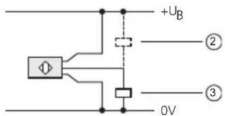
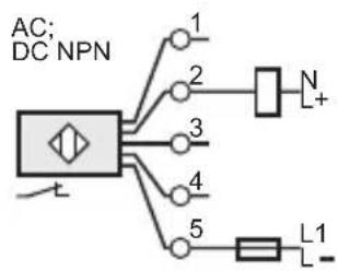
Programming via wiring (KDE - AC/DC PNP/NPN)4.4.1


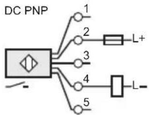
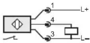
Type KDE - three-wire technology4.5
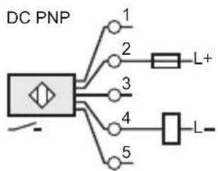
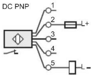
Programming via wiring (KDE - DC PNP/NPN)4.5.1
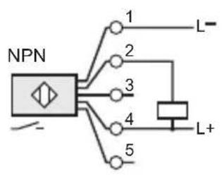
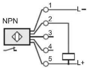

flowchart
graph TD
    A["Switch"] --> B["Component 1"]
    A --> C["Component 2"]
    A --> D["Component 4"]
    B --> E["L+"]
    C --> F["L-"]

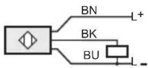
Core colours of ifm sockets:
BN (brown), BU (blue), BK (black).
Type KIE / KGE4.6
Programming via the wire link4.6.1
programmed as normally open (wire link closed, factory setting)1:
programmed as normally closed (wire link open)2:
Use an appropriate tool to disconnect the wire link.
Operating and display elements5
Example type KB5.1
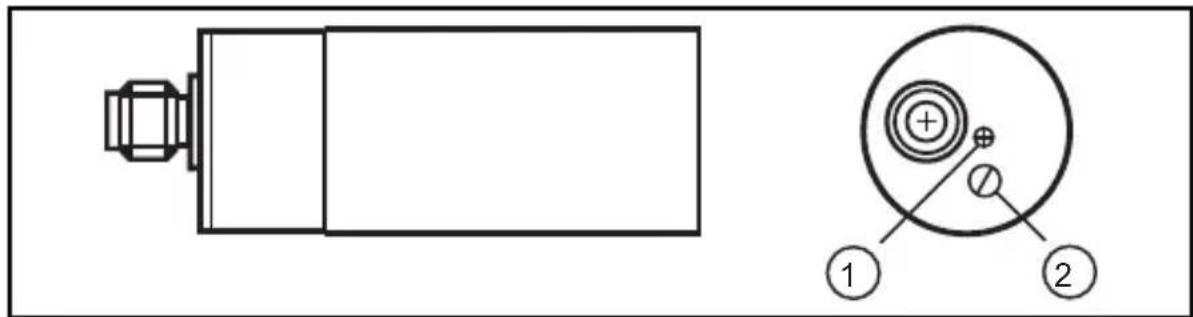
LED1:
potentiometer2:
Settings6
Sensing range6.1
Set the sensing range via the potentiometer using the enclosed screwdriver.
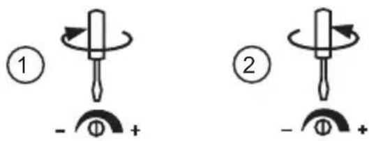
increase the sensing range1:
reduce the sensing range2:
Operation7
Check whether the unit operates correctly. Bring about a sensor response by taking suitable measures.
Display by LEDs:
LED yellow out: switching output disabled
LED yellow on switching output enabled
Maintenance, repair, disposal8
The operation of the unit is maintenance-free. To ensure a correct function:
keep the sensing face and a clear space, if any, free from deposits and foreign bodies.
It is not possible to repair the unit.
After use dispose of the unit in an environmentally friendly way in accordance with the applicable national regulations.
Definitions9
Active zone
Area above the sensing face in which the sensor reacts to the approach of the target.
Output function
Normally open: object within the active zone - output switched.
Normally closed: object within the active zone - output blocked.
Programmable: choice between normally closed or normally open.
Positive switching: positive output signal (to L-).
Negative switching: negative output signal (to L+).
Power-on delay time
The time the sensor needs to be ready for operation after application of the operating voltage (in the millisecond range).
Hysteresis
Difference between the switch-on and the switch-off point.
Leakage current
Current for the internal supply of 2-wire units, also flows through the load when the output is blocked.
Current consumption
Current for the internal supply of 3-wire DC units.
Switch point drift
Shifting of the switch point owing to changes of the operating conditions (e.g. temperature, pressure, air humidity).
Short-circuit protection
ifm sensors which are protected against excessive current by means of a pulsed short-circuit protection. The inrush current of incandescent lamps, electronic relays and low resistance loads may cause this protection to cut in and turn the sensor off!
Operating voltage
The voltage range in which the sensor functions safely. A stabilised and smoothed direct voltage should be used! Take into account residual ripple!
Technical data and further information at www.ifm.com → Select your country → Data sheet direct:
UK


Contenu
natural_image
Simple line drawing of a device with a switch and circular button (no text or symbols)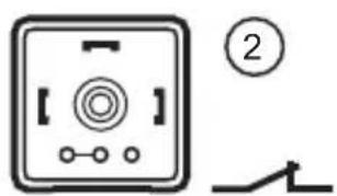
Type KDE - technologie 3 fils4.5
LED1:
Potentiomètre2:
Réglages6
Portée6.1
Zone active / face active
- Inhalt
- Einstellungen6
- Schaltabstand6.1
- Preliminary note
- Safety instructions1
- Functions and features2
- Installation3
- Notes on flush and non-flush installation3.1
- Electrical connection4
- Wiring 4.1
- Programming4.2
- Type KI (with connector)4.3
- Programming via wiring (KGE - DC PNP/NPN)4.3.2
- Type KDE - two-wire technology4.4
- Type KDE - three-wire technology4.5
- Programming via wiring (KDE - DC PNP/NPN)4.5.1
- Type KIE / KGE4.6
- Programming via the wire link4.6.1
- Operating and display elements5
- Example type KB5.1
- Settings6
- Sensing range6.1
- Operation7
- Maintenance, repair, disposal8
- Definitions9
- Active zone
- Output function
- Power-on delay time
- Hysteresis
- Leakage current
- Current consumption
- Switch point drift
- Short-circuit protection
- Operating voltage
- Contenu
- Type KDE - technologie 3 fils4.5
- Réglages6
- Portée6.1
- Zone active / face active
Brand : IFM
Model : KI5209
Category : Capacitive proximity sensor