
AC2611 - Electronic module IFM - Free user manual and instructions
Find the device manual for free AC2611 IFM in PDF.
| Product type | AS-i slave electronic module |
| Brand | IFM |
| Model | AC2611 |
| Power supply | 24 V ±20% via AS-i network or external PELV |
| Maximum consumption | 60 mA |
| Output type | Configurable current or voltage (P0) |
| Voltage measurement range | 0...10 V |
| Current measurement range | 0...20 mA or 4...20 mA |
| Resolution | 6, 9, 12 or 15 bits |
| Acquisition time | < 28 ms |
| Max number of modules per master | 31 |
| Min load resistance voltage output | > 10 kΩ |
| Max load resistance current output | < 500 Ω |
| Ramp function | Enablable/disableable via parameter P2 |
| Transmission | Single or double (parameter P3) |
| LED indicators | AS-i supply (green), auxiliary supply (green), internal fault (red), output fault (red) |
| Addressing | Free address 1 to 31 (default 0) |
| Mounting | 35 mm rail or panel (accessory E70119) |
| Galvanic isolation | Up to 500 V with respect to AS-i system |
| Protection | PELV |
| Accessories | LCD display E70127, addressing unit |
Frequently Asked Questions - AC2611 IFM
User questions about AC2611 IFM
0 question about this device. Answer the ones you know or ask your own.
Ask a new question about this device
Download the instructions for your Electronic module in PDF format for free! Find your manual AC2611 - IFM and take your electronic device back in hand. On this page are published all the documents necessary for the use of your device. AC2611 by IFM.
USER MANUAL AC2611 IFM
Function and features
The AS-i module operates as a slave with a bidirectional data exchange in the AS-i network (AS-i profile: S 7.1).
- Current or voltage output
- Max. number of modules per master: 31
- Minimum load resistance voltage measurement >10k
Maximum load resistance current measurement < 500 - Time for converting the measured value in the slave < 28ms
- Actuator supply via the AS-i network (internal max. 60mA, 24V ± 20% ) or external supply 24V ± 20% ; PELV
- Resolution of the analog values in steps of 6, 9, 12, 15 bits
- No calibration required by the user
Ramp function
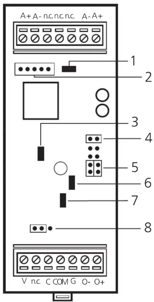

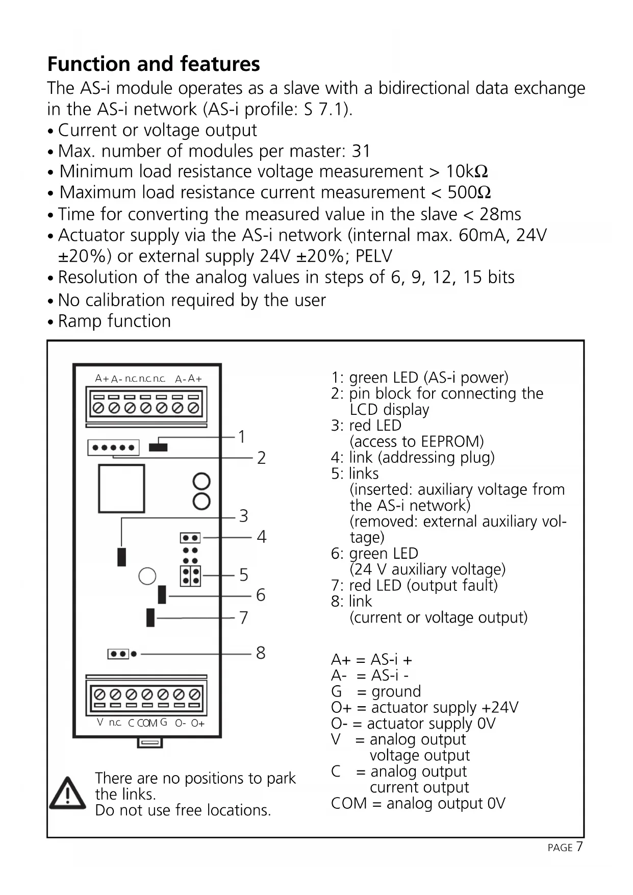
There are no positions to park the links.
Do not use free locations.
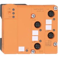
1: green LED (AS-i power)
2: pin block for connecting the LCD display
3: red LED (access to EEPROM)
4: link (addressing plug)
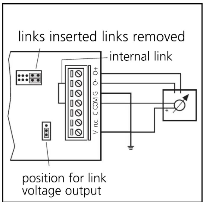
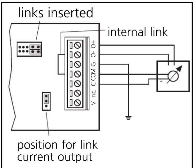
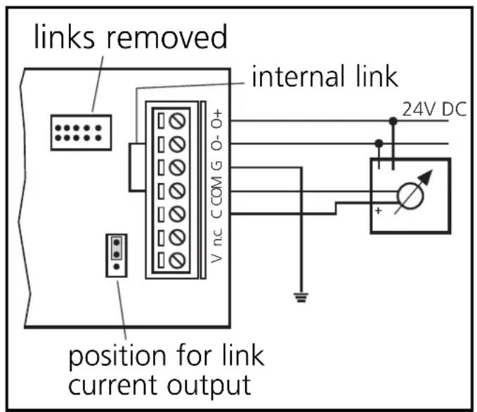
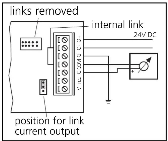
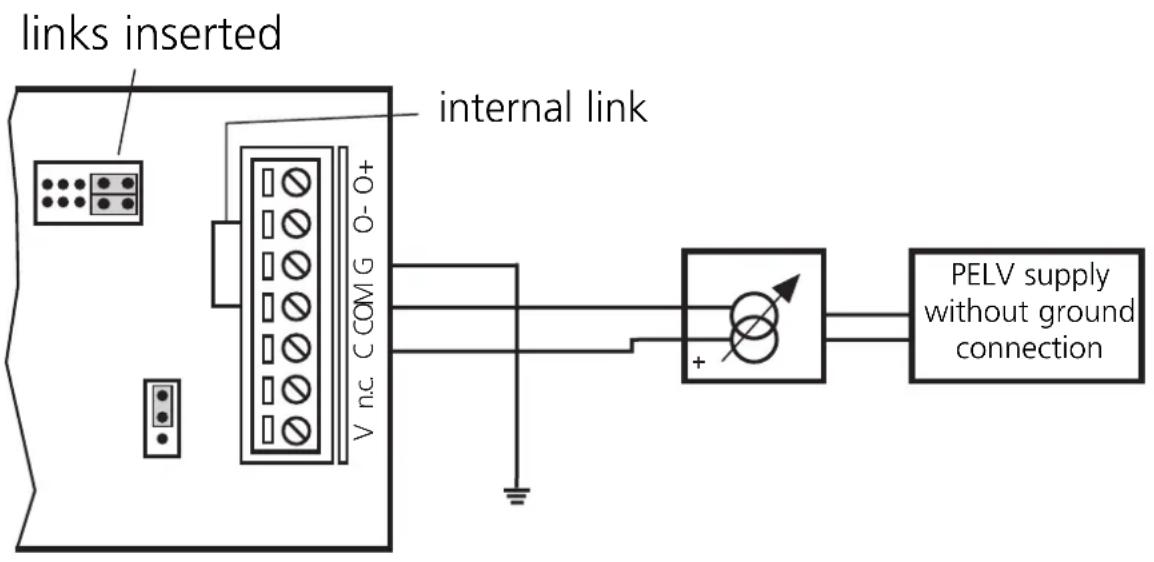
5: links (inserted: auxiliary voltage from the AS-i network) (removed: external auxiliary voltage)
6: green LED (24 V auxiliary voltage)
7: red LED (output fault)
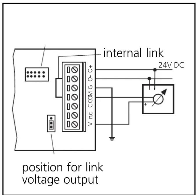
8: link (current or voltage output)
$$ \begin{array}{l} A + = A S - i + \ A - = A S - i - \ G = \text {g r o u n d} \ O + = \text {a c t u a t o r s u p p l y} + 2 4 V \ O - = a c t u a t o r s u p p l y O V \ \begin{array}{c} V = \text {a n a l o g o u t p u t} \ \text {v o l t a g e o u t p u t} \end{array} \ \begin{array}{c} C = \text {a n a l o g o u t p u t} \ \text {c u r r e n t o u t p u t} \end{array} \ \mathrm {C O M} = \text {a n a l o g o u t p u t 0 V} \ \end{array} $$
Mounting
Mount the module onto a 35mm rail or fasten it onto a mounting device (accessories required E70119).
Electrical connection
The actuator must always be ungrounded!
If an external potential is used, it must be a PELV voltage. The electrical separation to the AS-i system is rated for 500V.
Links may only be inserted or removed with the system being disconnected.
Voltage output
Parameter setting:
P0 = 1: voltage output
P1 = 1: measuring range 0 ... 10V, resolution 0.3mV
or P1 = 0 : measuring range 0 ... 10V, resolution 1mV
Supply via AS-i External supply
Current output
Parameter setting:
P0 = 0 : current output
P1 = 1: measuring range 0 ... 20mA
or P1 = 0 : measuring range 4 ... 20mA
Current output for current sink with 24V supply
Supply via AS-i
External supply
Current output
Parameter setting:
P0 = 0 : current output
P1 = 1: measuring range 0 ... 20mA
or P1 = 0 : measuring range 4 ... 20mA
2-wire current sinks 4 .. 20 mA without intrinsic supply
Supply via AS-i External supply
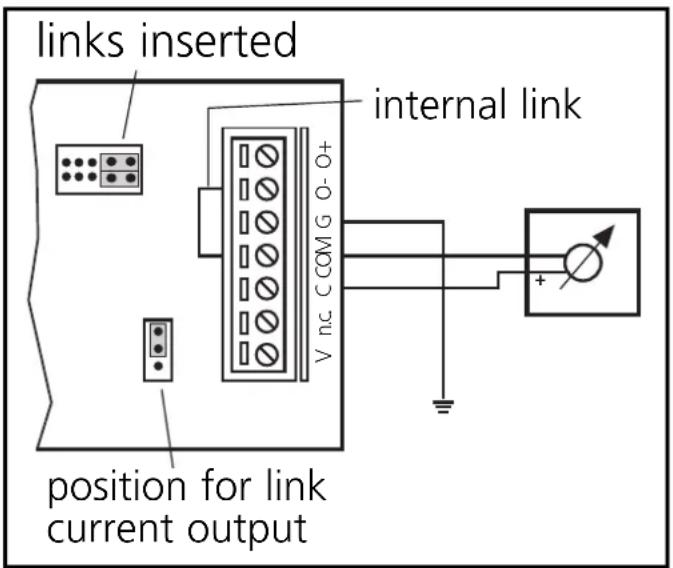
2-wire current sinks 4 ... 20 mA with intrinsic supply
Parameter setting

The parameter bits must not be changed during operation.
| Parameter bit | Type Designation | Description | |
| P0 output | output signal | 1* voltage output (0...10V) 0 current output (0/4..20mA) | |
| P1 output | measuring range | 1* 0...20mA (0...7FFF)hex or 0...10V (0...7FFF)hex 0 4...20mA (0...7FFF)hex or 0.10V (0...2710)hex | |
| P2 output | ramp function | * | 1* off 0 on |
| P3 output | data transmission | 1* single transmission 0 double transmission | |
| * setting upon request | * default setting | ||

After an interference individual values can be transferred incorrectly. This can be avoided by a double transmission of the output values. To do so, set the parameter bit P3 to 0.
Addressing
Connect the addressing unit to the terminals A+ and A- by means of a cable plug. Remove the addressing plug and assign a free address between 1 and 31 (factory setting is 0).
Pin connection of a cable plug: 1 = A+/brown, 3 = A-/blue Leave the addressing plug removed.
Operation
The data transmission/representation of the measured value in the host is controlled by the user program. In conjunction with the controller, the evaluation is performed by a corresponding function block (AC0314).
(If other masters are used, function blocks for the protocol 7.1 are needed).
- Green LED (1) (Power) is lit: AS-i supply voltage o.k.
- Red LED (3) is lit: internal fault, e.g. sum error
- Red LED (3) flashes: memory settings are loaded
- Green LED (6) is lit: 24V auxiliary voltage o.k.
- Red LED (7) is lit: output fault
Accessories
As an accessory a display board is available (E70127). The measured value is displayed according to the selected setting. The display is independent of the AS-i communication, the places after the comma are not displayed.
$$ A + = A S - i + $$
A- = AS-i -
G = terre
Brand : IFM
Model : AC2611
Category : Electronic module