
OnAir Panel 2IP - Heating Chauvet - Free user manual and instructions
Find the device manual for free OnAir Panel 2IP Chauvet in PDF.

| Product Type | Professional LED luminaire for stage and event lighting |
| Brand | Chauvet |
| Model | OnAir Panel 2IP |
| Power Supply | 100-240 V~, 50/60 Hz (universal) or 28 V DC (SELV) |
| Power Consumption | Up to 8 units daisy-chained at 230 V |
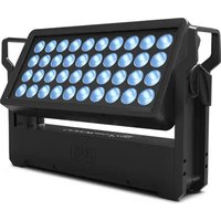
| Light Source | LED RGBW (Red, Green, Blue, White) |
| Color Temperature | 2800 K to 8000 K (adjustable) |
| Protection Rating | IP65 (weather-resistant, temporary outdoor use) |
| Control Protocols | DMX512, CRMX™ wireless, Art-Net™, sACN, RDM |
| DMX Personalities | 1Ch, 3Ch, 4Ch, 5Ch, 6Ch, 8Ch, 11Ch, 15Ch, 16Ch, 18Ch, 23Ch, 32Ch, XYBasic(6), XYExtended(10) |
| Connectivity | DMX 5-pin, etherCON RJ45, USB (firmware update), PowerCON, XLR 3-pin DC |
| Wireless Range | Up to 300 m (900 ft) under optimal conditions (CRMX™) |
| Display | Digital display with adjustable backlight |
| Built-in Functions | Dimmer, strobe, effect macros, red shift, dimming curves, master/slave mode |
| Ambient Temperature | Operation: -30 °C to 45 °C; min. startup -20 °C |
| Mounting | Omega brackets and hooks included, safety cable required for overhead mounting |
| Maintenance | Clean with a soft, dry cloth; do not immerse |
| Safety | Do not stare directly at the light source; housing hot during operation; minimum distance of 50 cm from surfaces |
| Weight | Not specified in the manual |
| Dimensions | Not specified in the manual |
Frequently Asked Questions - OnAir Panel 2IP Chauvet
User questions about OnAir Panel 2IP Chauvet
0 question about this device. Answer the ones you know or ask your own.
Ask a new question about this device
Download the instructions for your Heating in PDF format for free! Find your manual OnAir Panel 2IP - Chauvet and take your electronic device back in hand. On this page are published all the documents necessary for the use of your device. OnAir Panel 2IP by Chauvet.
USER MANUAL OnAir Panel 2IP Chauvet
Model ID: ONAIRPANEL2IP
About This Guide
The onAir IP Panel 2 Quick Reference Guide (QRG) has basic product information such as mounting, menu options, and DMX values. Download the User Manual from www.chauvetprofessional.com for more details.
Disclaimer
The information and specifications contained in this QRG are subject to change without notice.
LIMITED WARRANTY
FOR WARRANTY REGISTRATION AND COMPLETE TERMS AND CONDITIONS PLEASE VISIT OUR WEBSITE. For Customers in the United States and Mexico: www.chauvetlighting.com/warranty-registration.
For Customers in the United Kingdom, Republic of Ireland, Belgium, the Netherlands, Luxembourg, France, and Germany: www.chauvetlighting.eu/warranty-registration.
Chauvet warrants that this product shall be free from defects in material and workmanship under normal use, for the period specified in, and subject to the exclusions and limitations set forth in the full limited warranty on our website. This warranty extends only to the original purchaser of the product and is not transferable. To exercise rights under this warranty, you must provide proof of purchase in the form of an original sales receipt from an authorized dealer that shows the product name and date of purchase. THERE ARE NO OTHER EXPRESS OR IMPLIED WARRANTIES. This warranty gives you specific legal rights. You may also have other rights that vary from state to state and country to country. This warranty is valid only in the United States, United Kingdom, Republic of Ireland, Belgium, the Netherlands, Luxembourg, France, Germany and Mexico. For warranty terms in other countries, please consult your local distributor.
Safety Notes
- The luminaire should be positioned so that prolonged staring into the luminaire at a distance closer than 19.7 in (50 cm) is not expected.
- If the external flexible cable or cord of this luminaire is damaged, it shall be replaced by a special cord or cord exclusively available from the manufacturer or his service agent.
- The light source contained in this luminaire shall only be replaced by the manufacturer or his service agent or a similar qualified person.
- The luminaire is intended for professional use only.
- DO NOT open this product. It contains no user-serviceable parts.
- DO NOT look at the light source when the product is on.
- To eliminate unnecessary wear and improve its lifespan, during periods of non-use completely disconnect the product from power via breaker or by unplugging it.
- CAUTION: When transferring product from extreme temperature environments, (e.g. cold truck to warm humid ballroom) condensation may form on the internal electronics of the product. To avoid causing a failure, allow product to fully acclimate to the surrounding environment before connecting it to power.
- CAUTION: This product's housing may be hot when lights are operating.
• Mount this product in a location with adequate ventilation, at least 20 in (50 cm) from adjacent surfaces.
• DO NOT leave any flammable material within 7.87 in (20 cm) of this product while operating or connected to power. - USE a safety cable when mounting this product overhead.
- DO NOT submerge this product (IP65). Regular outdoor operation is fine.
- DO NOT operate this product if the housing, lenses, or cables appear damaged.
- DO NOT connect this product to a dimmer or rheostat.
- ONLY connect this product to a grounded and protected circuit.
- ONLY use the hanging/mounting bracket or the handles to carry this product.
• In the event of a serious operating problem, stop using immediately.
• The maximum ambient temperature is 113 °F (45 °C). Do not operate this product at higher temperatures. - The minimum startup temperature is -4°F (-20°C). Do not start the product at lower temperatures.
• The minimum ambient temperature is -22°F ( -30°C ). Do not operate the product at lower temperatures.
FCC Compliance
This device complies with Part 15 Part B of the FCC Rules. Operation is subject to the following two conditions:
-
This device may not cause harmful interference, and
-
This device must accept any interference received, including interference that may cause undesired operation. Any changes or modifications not expressly approved by the party responsible for compliance could void the user's authority to operate the equipment.
RF Exposure Warning for North America, and Australia
Warning! This equipment complies with FCC radiation exposure limits set forth for an uncontrolled environment. This equipment should be installed and operated with a minimum distance of 20cm between the radiator and your body. This transmitter must not be co-located or operating in conjunction with any other antenna or transmitter.
Contact
Outside the U.S., U.K., Ireland, Benelux, France, Germany, or Mexico, contact your distributor to request support or return a product. Refer to Contact Us at the end of this QRG for contact information.
What is Included
- onAir IP Panel 2
- Seetronic Powerkon IP65 cable
- Omega bracket with mounting hardware
• Junior or pin
- Quick Reference Guide
AC Power
This product has an auto-ranging power supply that can work with an input voltage range of 100–240 V\~, 50/60 Hz.
Power Linking
You can link up to 3 onAir IP Panel 2 products at 100 V, 4 products at 120 V, 7 products at 208 V, 8 products at 230 V, or 8 products at 240 V. Never exceed this number. Power linking cords can be purchased separately.
AC Plug
| Connection | Wire (U.S.) | Wire (Europe) | Screw Color |
| AC Live Black Brown Yellow/Brass | |||
| AC Neutral | White | Blue | Silver |
| AC Ground | Green/Yellow | Green/Yellow | Green |
DC Power
This product has a 3-pin IP65 XLR power input port that can work with an input voltage of 28 V DC which is SELV voltage supplied by short-circuit-proof power supply.
If AC power and DC power are input to the product at the same time, the product will automatically give priority to AC power input.
To eliminate unnecessary wear and improve its lifespan, during periods of non-use completely disconnect the product from power via breaker or by unplugging it.
Signal Connections
The onAir IP Panel 2 will work with a controller or controller software using a wired DMX connection, a wireless Lumenradio CRMX ™ connection, or an Ethernet connection, If using other Art-Net ™ or sACN-compatible products with the onAir IP Panel 2, each can be controlled individually on a single network. See the User Manual for information about how to connect and configure the product for these signals.
Control Personalities
The onAir IP Panel 2 uses DMX, CRMX™, Art-Net™, and sACN for its control personalities: 1Ch, 3Ch, 4Ch, 5Ch, 6Ch, 8Ch, 11Ch, 15Ch, 16Ch, 18Ch, 23Ch, 32Ch, XYBasic(6), and XYExtended(10).
DMX Connection
The onAir IP Panel 2 will work with a DMX controller using a 5-pin DMX data connection or a wireless CRMX ™ connection. A DMX Primer is available from www.chauvetprofessional.com.
Art-Net™ Connection
Art-Net™ is an Ethernet protocol that uses TCP/IP which transfers a large amount of DMX512 data using an Neutrik® etherCON® RJ45 connection over a large network. An Art-Net™ protocol document is available from www.chauvetprofessional.com. Chauvet Professional recommends using unicast Art-Net™ for best results.
Art-Net™ designed by and copyright Artistic Licence Holdings Ltd.
sACN Connection
Also known as ANSI E1.31, Streaming-ACN is an Ethernet protocol that uses the layering and formatting of Architecture for Control Networks to transport DMX512 data over IP or any other ACN compatible network.
RDM (Remote Device Management)
Remote Device Management, or RDM, is a standard for allowing DMX-enabled devices to communicate bi-directionally along existing DMX cabling. Check the DMX controller's User Manual or with the manufacturer as not all DMX controllers have this capability. The onAir IP Panel 2 supports RDM protocol that allows feedback to make changes to menu map options. Download the User Manual from www.chauvetprofessional.com for more details.
USB Software Update
The onAir IP Panel 2 allows for software update through USB using the built-in USB port. To update the software using USB flash drive, do the following:
- Power on the fixture and plug the flash drive into the USB port.
- Once the flash drive has been detected, the message "Upgrade Firmware" will be displayed. Press
. - If a different message appears on the display, search for the updated software in the Main Menu (Update Firmware) and select from Only This Unit, Multiple Units, or Other Fixture Type. A list of the software update files will be displayed.
- Select the file that needs to be uploaded. The message "Are you sure?" will be displayed. Press
. - If the selected file is correct, the upgrade will be completed. Restart the fixture.
- If the selected file is incorrect, the upgrade will fail, and the display will go back to the main interface. Repeat steps 1-3 using the correct file.

The “Other Fixture Type” option can only be selected for connected products compatible with the Upload 03 (the first 2 digits of the item code must be 03).
Wireless Operation
In optimal conditions, the onAir IP Panel 2 can operate up to 300 m (900 ft) away from the CRMX ™ transmitter, The CRMX ™ receiver in the onAir IP Panel 2 must be paired with the CRMX ™ transmitter for wireless operation.
Initial Setup
- Turn the CRMX TM transmitter on.
- Connect the CRMX TM transmitter to a DMX controller.
- Place the onAir IP Panel 2 within 300 m from the CRMX™ transmitter.
- Turn the onAir IP Panel 2 on.
Configuration
- From the onAir IP Panel 2's control panel, go to DMX Address.
- Select the start address, as with any other DMX compatible product.
- Go to Wireless Setting >Receive On/Off.
- Select On. (The Signal Strength Indicator will show a ? in front of the bars)
- Press the reset button on the CRMX™ transmitter. (The Signal Strength Indicator on the onAir IP Panel 2 will show a 5 in front of the bars for 3 seconds while a connection is established.)
Product Pairing
If the onAir IP Panel 2 has already been paired with the CRMX™ transmitter, the Signal Strength Indicator on top of the display will show the strength of the signal. In this case, the onAir IP Panel 2 is ready to work in Wireless mode.
Pairing the onAir IP Panel 2 and a New CRMX™ Transmitter
- From the onAir IP Panel 2 control panel, go to Wireless Setting >Receive Reset.
- Select Yes.
- From the CRMX™ transmitter, press
. The signal indicator on the transmitter will flash. - Once the transmitter has found the onAir IP Panel 2, the signal indicator on the CRMX™ transmitter will illuminate solid.
- The display screen on the onAir IP Panel 2 will show the strength of the signal.

CRMX™ operation can be interrupted or inhibited by people or liquid masses, including water or snow, between the transmitter and receiver. For best results, keep the area between the transmitter and receiver clear of any liquid masses.
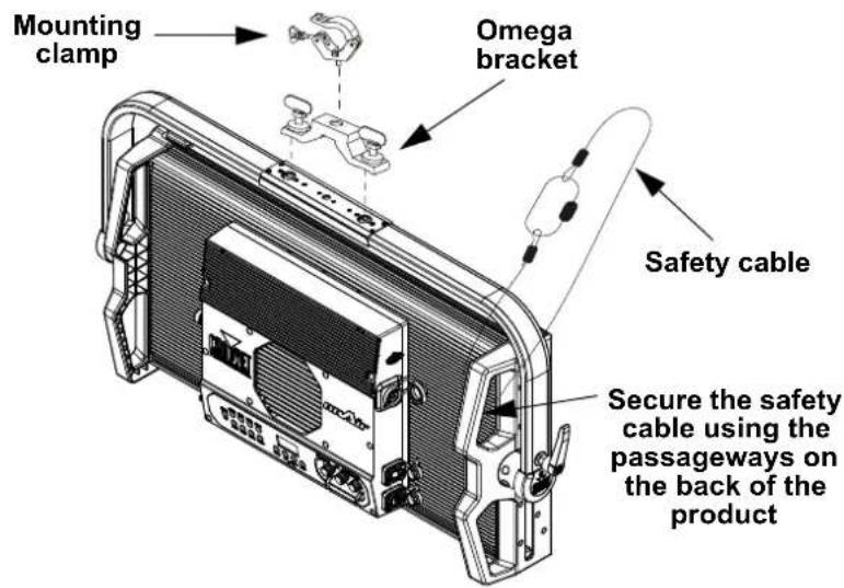
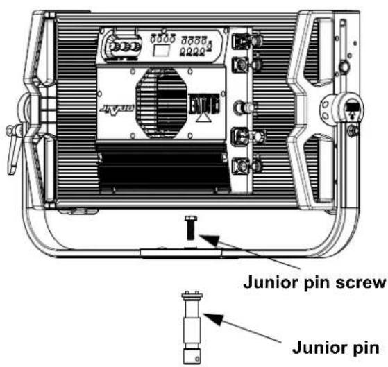
Mounting
Before mounting this product, read the Safety Notes. Make sure the mounting clamps are capable of supporting the weight of the product. Mounting clamps sold separately. For our CHAUVET Professional line of mounting clamps, go to http://trusst.com/products.
Mounting Diagram
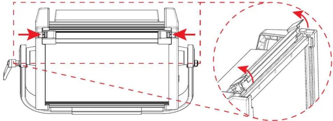
Accessory Slots
The onAir IP Panel 2 has 2 accessory slots that can be accessed by pressing the accessory slot tabs inward and opening the hinged accessory slot cover.

- Do not use when the diffuser is removed. The diffuser cannot be removed when the fixture is powered on.
-
For fixed mounted luminaires, the risk group shall not exceed RG1 at the distance obtaining 500 lx.
-
The back slot is for a diffuser or intensifier.
- The front slot is for accessories such as a honeycomb or barndoors.
Home Screen
The home screen of the onAir IP Panel 2 shows the current settings and status of the product.
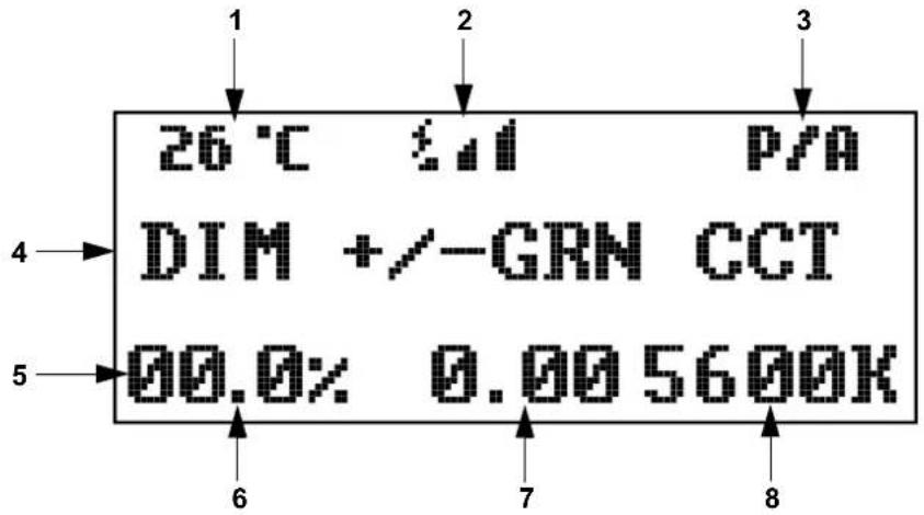
Number Description
| 1 Current product temperature | |
| 2 Current wireless signal status | |
| 3 Current preset or preset bank | |
| 4 | Middle line shows current control mode. Shows DIM +/-GRN CCT in CCT mode, DIM HUE SAT in HSV mode, DIM X Y in XY Control mode, Master Mode in master mode, Slave Mode in slave mode, etc. |
| 5 Bottom line shows details of the current control mode | |
| 6 Current dimmer or intensity value (00.0–100%) in CCT, HSV, or XY Control mode | |
| 7 | Current +/- green value (-0.25–+0.25) in CCT mode, hue value (000–360°) in HSV mode, or X value (0.00–0.850) in XY Control mode |
| 8 | Current color temperature (2800–8000K) in CCT mode, saturation value (000–255) in HSV mode, or Y value (0.00–0.850) in XY Control mode |
Control Panel Description
| Button/Knob Function | |
| Exits from the current menu or function | |
| Enables the currently displayed menu or sets the currently selected value into the selected function | |
| Navigates upwards through the menu list or increases the numeric value when in a function | |
| Navigates downwards through the menu list or decreases the numeric value when in a function | |
| Increases or decreases the dimmer value or intensity | |
| Increases or decreases the hue value or X value | |
| Increases or decreases the color temperature, saturation, or Y value | |
| Toggles between A presets (built-in) and B presets (custom) | |
| Selects a preset. Hold for 3 seconds to save the current look to the selected B preset. | |
Menu Map
Refer to the onAir IP Panel 2 product page on www.chauvetprofessional.com for the latest menu map.
| Main Level Programming Levels Description | |||||
| Protocol | DMX512 | Sets the control protocol | |||
| Artnet | |||||
| sACN | |||||
| DMX Address | 001-509* | Selects DMX address (*Highest channel restricted to personality chosen) | |||
| DMX Channel | 1Ch | Preset CCTs | Hue | <-25-25> | 1-channel: selects a preset CCT and hue |
| Manual Color Mixer | Red | <000-255> | 1-channel: combine red, green, blue, and white to make a custom color (0-100%) | ||
| Green <000 | 0-255> | ||||
| Blue | <000-255> | ||||
| White | <000-255> | ||||
| 3Ch | 3-channel: dimmer, color temperature, hue | ||||
| 4Ch | 4-channel: RGBW | ||||
| 5Ch | 5-channel: 16-bit dimmer, color temperature, hue, strobe | ||||
| 6Ch | 6-channel: dimmer, RGBW, strobe | ||||
| 8Ch | 8-channel: 16-bit RGBW | ||||
| 11Ch | 11-channel: 16-bit dimmer, RGBW, strobe, color temperature, hue, effect macros, and speed | ||||
| 15Ch | 15-channel: 16-bit dimmer, 16-bit RGBW, strobe, color temperature, hue, effect macros, and speed | ||||
| 16Ch | 16-channel: RGBW 1-4 | ||||
| 18Ch | 18-channel: dimmer, RGBW 1-4, and strobe | ||||
| 23Ch | 23-channel: dimmer, RGBW 1-4, strobe, color temperature, hue, effect macros and speed, control | ||||
| 32Ch | 32-channel: 16-bit RGBW 1-4 | ||||
| XYBasic(6) | 6-channel: 16-bit dimmer, 16-bit X, 16-bit Y | ||||
| XYExtended(10) | 10-channel: 16-bit dimmer, 16-bit X, 16-bit Y, strobe, effect macros and speed, control | ||||
| Static | CCT Control | Correlated color temperature control | |||
| HSV Control | Hue, saturation, value control | ||||
| XY Control | X and Y coordinate control | ||||
| 2800K Preset CCTs | Dimmer | <000-255> | Selects preset color temperature, dimmer and hue | ||
| 2900K | |||||
| 3000K | |||||
| 3100K | |||||
| 3200K | |||||
| 3300K | |||||
| 3400K | |||||
| 3500K | |||||
| 3600K | |||||
| Static (cont.) | Preset CCTs (cont.) | 3700K3800K3900K4000K4100K4200K4300K4400K4500K4600K4700K4800K4900K5000K5100K5200K5300K5400K5500K5600K5700K6000K6500K7000K7500K8000K | DimmerHue | <000-255><-25-25> | Selects preset color temperature, dimmer and hue |
| Manual Color Mixer | RedGreenBlueWhite | <000-255> | Combine red, green, blue, and white to make custom color (0-100%) | ||
| Effect Macros | Color Chase | <001-100> Selects effect macro and speed | |||
| Police Car | |||||
| Firetruck | |||||
| Fire | |||||
| Clouds | |||||
| Fireworks | |||||
| Paparazzi | |||||
| Lightning | |||||
| Red Shift | On | Enables or disables red shift | |||
| Off | |||||
| Master/Slave | Master Standalone mode | ||||
| Slave Slave mode | |||||
| DMX Loss | Hold Last Holds last signal received | ||||
| Stop DMX Holds output | |||||
| Blackout Blacks out the product | |||||
| Dimmer Curve | S CurveLinearSquareInverse Square | Sets the dimmer curve | |||
| Dimmer Mode | Off Instantaneous dimmer | ||||
| Dimmer 1-3 | Dimmer mode, fast (1) to slow (3) | ||||
| Main Level | Programming Levels | Description | |||
| Color Calibration | Off Color calibration off | ||||
| User Calibration | Red | <125-255> | Sets maximum red LED value | ||
| Green Sets maximum green LED value | |||||
| Blue Sets maximum blue LED value | |||||
| White Sets maximum white LED value | |||||
| Factory Calibration Color calibration set by factory | |||||
| LED Frequency | 600Hz1200Hz2000Hz4000Hz6000Hz25KHz | Sets the Pulse Width Modulation frequency | |||
| Fan Mode | Auto Sets the fan to auto mode | ||||
| On Sets the fan to always on | |||||
| Off Sets the fan to always off | |||||
| Silent Sets the fan to silent | |||||
| Wireless Setting | Receive On/Off | Off | Enables/disables CRMXTM | ||
| On | |||||
| Receive Reset | No | Resets wireless receiver | |||
| Yes | |||||
| Wireless To DMX | No | Enables/disables wireless to DMX | |||
| Yes | |||||
| Back Light | 10S | Turns off display backlight after 10 seconds of inactivity | |||
| 30S Turns off display backlight after 30 seconds | |||||
| 2Min Turns off display backlight after 2 minutes of | |||||
| Always On Display backlight always on | |||||
| Ethernet Setting | Universe | 000-255 (Art-netTM) | Sets the Art-NetTM or sACN universe | ||
| 001-256 (sACN) | |||||
| Start Channel | 001-512 | Sets the starting channel | |||
| IP Address | 2 | 000-255.000-255.000-255 | Sets the IP address | ||
| 10 | |||||
| 239 | |||||
| Ethernet To DMX | No | Enables/disables Ethernet to DMX | |||
| Yes | |||||
| Information | Fixture Hours | <______H> | Shows total hours the product has been powered on | ||
| LED Hours | <______H> | Shows total hours the LEDs have been powered on | |||
| Disp Version | Shows current display version | ||||
| Drv Version | Shows current driver version | ||||
| Net Version | Shows current net version | ||||
| UID | 21A40139______ | Shows product UID | |||
| Update Firmware | Only This Unit | _____.CHL | Selects an update file for this product, or shows “No such file!” | ||
| ... | |||||
| Multiple Units | _____.CHL | Selects an update file for this and connected onAir IP Panel 2 products, or shows “No such file!” | |||
| ... | |||||
| Other Fixture Type | _____.CHL | Selects an update file for other connected products, or shows “No such file!” | |||
| ... | |||||
| Factory Reset | No | Resets the product to factory default settings | |||
| Yes | |||||
DMX Values
XYExtended(10)
| Channel Function Value Percent/Setting | |||
| 1 Dimmer 000 ⇔ 255 0–100% | |||
| 2 | Fine dimmer | 000 ⇔ 255 | 0–100% |
| 3 | X coordinate | 000 ⇔ 255 | 0–100% |
| 4 | Fine X coordinate | 000 ⇔ 255 | 0–100% |
| 5 | Y coordinate | 000 ⇔ 255 | 0–100% |
| 6 | Fine Y coordinate | 000 ⇔ 255 | 0–100% |
| 7 | S t r o | 000 ⇔ 010b011 ⇔ 255 | No functionStrobe, slow to fast |
| 8 | Effect macros | 000 ⇔ 255 | See the Effect Macros Chart |
| 9 | Effect macro speed | 000 ⇔ 255 | Speed, slow to fast |
| 10 | Control | 000 ⇔ 255 | See the Control Chart |
XYBasic(6)
| Channel | Function | Value | Percent/Setting |
| 1 Dimmer | 000 ⇔ 255 0–100% | ||
| 2 | Fine dimmer | 000 ⇔ 255 | 0–100% |
| 3 | X coordinate | 000 ⇔ 255 | 0–100% |
| 4 | Fine X coordinate | 000 ⇔ 255 | 0–100% |
| 5 | Y coordinate | 000 ⇔ 255 | 0–100% |
| 6 | Fine Y coordinate | 000 ⇔ 255 | 0–100% |
32Ch
| Channel Function Value Percent/Setting | |||
| 1 | Red 1 | 000 ⇔ 255 | 0–100% |
| 2 | Fine red 1 | 000 ⇔ 255 | 0–100% |
| 3 | Green 1 | 000 ⇔ 255 | 0–100% |
| 4 | Fine green 1 | 000 ⇔ 255 | 0–100% |
| 5 | Blue 1 | 000 ⇔ 255 | 0–100% |
| 6 | Fine blue 1 | 000 ⇔ 255 | 0–100% |
| 7 | White 1 | 000 ⇔ 255 | 0–100% |
| 8 | Fine white 1 | 000 ⇔ 255 | 0–100% |
| 9 | Red 2 | 000 ⇔ 255 | 0–100% |
| 10 | Fine red 2 | 000 ⇔ 255 | 0–100% |
| 11 | Green 2 | 000 ⇔ 255 | 0–100% |
| 12 | Fine green 2 | 000 ⇔ 255 | 0–100% |
| 13 | Blue 2 | 000 ⇔ 255 | 0–100% |
| 14 | Fine blue 2 | 000 ⇔ 255 | 0–100% |
| 15 | White 2 | 000 ⇔ 255 | 0–100% |
| 16 | Fine white 2 | 000 ⇔ 255 | 0–100% |
| 17 | Red 3 | 000 ⇔ 255 | 0–100% |
| 18 | Fine red 3 | 000 ⇔ 255 | 0–100% |
| 19 | Green 3 | 000 ⇔ 255 | 0–100% |
| 20 | Fine green 3 | 000 ⇔ 255 | 0–100% |
| 21 | Blue 3 | 000 ⇔ 255 | 0–100% |
| 22 | Fine blue 3 | 000 ⇔ 255 | 0–100% |
| 23 | White 3 | 000 ⇔ 255 | 0–100% |
| 24 | Fine white 3 | 000 ⇔ 255 | 0–100% |
| 25 | Red 4 | 000 ⇔ 255 | 0–100% |
| 26 | Fine red 4 | 000 ⇔ 255 | 0–100% |
| 27 | Green 4 | 000 ⇔ 255 | 0–100% |
| 28 | Fine green 4 | 000 ⇔ 255 | 0–100% |
| 29 Blue | 4 000 ⇔ 255 0–100% | ||
| 30 | Fine blue 4 | 000 ⇔ 255 | 0–100% |
| 31 White | 4 000 ⇔ 255 0–100% | ||
| 32 | Fine white 4 | 000 ⇔ 255 | 0–100% |
23Ch
| Channel Function Value Percent/Setting | |||
| 1 Dimmer 000 ⇔ 255 0–100% | |||
| 2 | Red 1 | 000 ⇔ 255 | 0–100% |
| 3 | Green 1 | 000 ⇔ 255 | 0–100% |
| 4 | Blue 1 | 000 ⇔ 255 | 0–100% |
| 5 | White 1 | 000 ⇔ 255 | 0–100% |
| 6 | Red 2 | 000 ⇔ 255 | 0–100% |
| 7 | Green 2 | 000 ⇔ 255 | 0–100% |
| 8 | Blue 2 | 000 ⇔ 255 | 0–100% |
| 9 | White 2 | 000 ⇔ 255 | 0–100% |
| 10 | Red 3 | 000 ⇔ 255 | 0–100% |
| 11 | Green 3 | 000 ⇔ 255 | 0–100% |
| 12 Blue 3 000 ⇔ 255 0–100% | |||
| 13 White 3 000 ⇔ 255 0–100% | |||
| 14 | Red 4 | 000 ⇔ 255 | 0–100% |
| 15 Green 4 000 ⇔ 255 0–100% | |||
| 16 Blue 4 000 ⇔ 255 0–100% | |||
| 17 White 4 000 ⇔ 255 0–100% | |||
| 18 Strobe | 000 ⇔ 010 No function011 ⇔ 255 Strobe, slow to fast | ||
| 19 | Color temperature | 000 ⇔ 255 See the Color Temperature Chart | |
| 20 Hue | 000 ⇔ 001 0002 ⇔ 255 -25–+25 | ||
| 21 | Effect macros | 000 ⇔ 255 See the Effect Macros Chart | |
| 22 | Effect macro speed | 000 ⇔ 255 Speed, slow to fast | |
| 23 | Control | 000 ⇔ 255 See the Control Chart | |
18Ch
| Channel Function Value Percent/Setting | |||
| 1 Dimmer 000 ⇔ 255 0–100% | |||
| 2 | Red 1 | 000 ⇔ 255 | 0–100% |
| 3 | Green 1 | 000 ⇔ 255 | 0–100% |
| 4 | Blue 1 | 000 ⇔ 255 | 0–100% |
| 5 | White 1 | 000 ⇔ 255 | 0–100% |
| 6 | Red 2 | 000 ⇔ 255 | 0–100% |
| 7 | Green 2 | 000 ⇔ 255 | 0–100% |
| 8 | Blue 2 | 000 ⇔ 255 | 0–100% |
| 9 | White 2 | 000 ⇔ 255 | 0–100% |
| 10 | Red 3 | 000 ⇔ 255 | 0–100% |
| 11 | Green 3 | 000 ⇔ 255 | 0–100% |
| 12 Blue | 3 000 ⇔ 255 0–100% | ||
| 13 White | 3 000 ⇔ 255 0–100% | ||
| 14 | Red 4 | 000 ⇔ 255 | 0–100% |
| 15 Green | 4 000 ⇔ 255 0–100% | ||
| 16 Blue | 4 000 ⇔ 255 0–100% | ||
| Channel Function Value Percent/Setting | ||
| 17 White 4 000 ⇔ 255 0–100% | ||
| 18 Strobe | 000 ⇔ 010 No function011 ⇔ 255 Strobe, slow to fast | |
16Ch
| Channel Function Value Percent/Setting | |||||||
| 1 | R | e | d | 1 | 000 ⇔ | 255 0–100% | |
| 2 | G | r | e | e | n | 1 | 000 ⇔ 255 0–100% |
| 3 | B | l | u | e | 1 | 000 ⇔ 255 0–100% | |
| 4 | W | h | i | t | e | 1 | 000 ⇔ 255 0–100% |
| 5 | R | e | d | 2 | 000 ⇔ | 255 0–100% | |
| 6 | G | r | e | e | n | 2 | 000 ⇔ 255 0–100% |
| 7 | B | l | u | e | 2 | 000 ⇔ 255 0–100% | |
| 8 | W | h | i | t | e | 2 | 000 ⇔ 255 0–100% |
| 9 | R | e | d | 3 | 000 ⇔ | 255 0–100% | |
| 10 Green 3 000 ⇔ 255 0–100% | |||||||
| 11 | Blue 3 | 000 ⇔ 255 | 0–100% | ||||
| 12 White 3 000 ⇔ 255 0–100% | |||||||
| 13 | Red 4 | 000 ⇔ 255 | 0–100% | ||||
| 14 Green 4 000 ⇔ 255 0–100% | |||||||
| 15 | Blue 4 | 000 ⇔ 255 | 0–100% | ||||
| 16 White 4 000 ⇔ 255 0–100% | |||||||
15Ch
| Channel Function Value Percent/Setting | |||
| 1 | Dimmer | 000 ⇔ 255 | 0–100% |
| 2 | Fine dimmer | 000 ⇔ 255 | 0–100% |
| 3 | Red | 000 ⇔ 255 | 0–100% |
| 4 | Fine red | 000 ⇔ 255 | 0–100% |
| 5 | Green | 000 ⇔ 255 | 0–100% |
| 6 | Fine green | 000 ⇔ 255 | 0–100% |
| 7 | Blue | 000 ⇔ 255 | 0–100% |
| 8 | Fine blue | 000 ⇔ 255 | 0–100% |
| 9 | W h i t | e | 000 ⇔ 255 0–100% |
| 10 | Fine white | 000 ⇔ 255 | 0–100% |
| 11 | Strobe | 000 ⇔ 010 | No function |
| 011 ⇔ 255 | Strobe, slow to fast | ||
| 12 | Color temperature | 000 ⇔ 255 | See the Color Temperature Chart |
| 13 Hue | 000 ⇔ 001 | 0 | |
| 002 ⇔ 255 | -25–+25 | ||
| 14 | Effect macros | 000 ⇔ 255 | See the Effect Macros Chart |
| 15 | Effect macro speed | 000 ⇔ 255 | Speed, slow to fast |
11Ch
| Channel Function Value Percent/Setting | ||||
| 1 | Dimmer | 000 ⇔ 255 | 0–100% | |
| 2 | Red | 000 ⇔ 255 | 0–100% | |
| 3 | Green | 000 ⇔ 255 | 0–100% | |
| 4 | Blue | 000 ⇔ 255 | 0–100% | |
| 5 | W h i t | e | 000 ⇔ 255 0–100% | |
| Channel | Function | Value | Percent/Setting |
| 6 | S t r o | 000 ⇔ 010 No function011 ⇔ 255 Strobe, slow to fast | |
| 7 | Color temperature | 000 ⇔ 255 | See the Color Temperature Chart |
| 8 | Hue | 000 ⇔ 001 0002 ⇔ 255 -25-+25 | |
| 9 | Effect macros | 000 ⇔ 255 | See the Effect Macros Chart |
| 10 | Effect macro speed | 000 ⇔ 255 | Speed, slow to fast |
| 11 | Control | 000 ⇔ 255 | See the Control Chart |
8Ch
| Channel | Function | Value | Percent/Setting |
| 1 | Red | 000 ⇔ 255 | 0–100% |
| 2 | Fine red | 000 ⇔ 255 | 0–100% |
| 3 | Green | 000 ⇔ 255 | 0–100% |
| 4 | Fine green | 000 ⇔ 255 | 0–100% |
| 5 | Blue | 000 ⇔ 255 | 0–100% |
| 6 | Fine blue | 000 ⇔ 255 | 0–100% |
| 7 | White | 000 ⇔ 255 | 0–100% |
| 8 | Fine white | 000 ⇔ 255 | 0–100% |
6Ch
| Channel | Function | Value | Percent/Setting |
| 1 | Dimmer | 000 ⇔ 255 | 0–100% |
| 2 | Red | 000 ⇔ 255 | 0–100% |
| 3 | Green | 000 ⇔ 255 | 0–100% |
| 4 | Blue | 000 ⇔ 255 | 0–100% |
| 5 | White | 000 ⇔ 255 | 0–100% |
| 6 | S t r o | 000 ⇔ 010 No functionb e011 ⇔ 255 Strobe, slow to fast | |
5Ch
| Channel | Function | Value | Percent/Setting |
| 1 | Dimmer | 000 ⇔ 255 | 0–100% |
| 2 | Fine dimmer | 000 ⇔ 255 | 0–100% |
| 3 | Color temperature | 000 ⇔ 255 | See the Color Temperature Chart |
| 4 | Hue | 000 ⇔ 001 0002 ⇔ 255 -25–+25 | |
| 5 | S t r o | 000 ⇔ 010 No function011 ⇔ 255 Strobe, slow to fast |
4Ch
| Channel | Function | Value | Percent/Setting |
| 1 | Red | 000 ⇔ 255 | 0–100% |
| 2 | Green | 000 ⇔ 255 | 0–100% |
| 3 | Blue | 000 ⇔ 255 | 0–100% |
| 4 | White | 000 ⇔ 255 | 0–100% |
3Ch
| Channel | Function Value Percent/Setting | ||
| 1 Dimmer 000 ⇔ 255 0–100% | |||
| 2 | Color temperature | 000 ⇔ 255 | See the Color Temperature Chart |
| 3 | Hue | 000 ⇔ 001 0002 ⇔ 255 | -25–+25 |
1Ch
| Channel Function Value Percent/Setting | |
| 1 Dimmer 000 ⇔ 255 0–100% | |
Effect Macros Chart
| Value Percent/Setting Value Percent/Setting | |||
| 000 ⇔ 010 | No function | 126 ⇔ 154 | Clouds |
| 011 ⇔ 039 | Color chase | 155 ⇔ 182 | Fireworks |
| 040 ⇔ 068 | Police car | 183 ⇔ 211 | Paparazzi |
| 069 ⇔ 096 | Firetruck | 212 ⇔ 240 | Lightning |
| 097 ⇔ 125 | Fire | 241 ⇔ 255 | No function |
Control Chart
| Value Percent/Setting Value Percent/Setting | |||
| 000 ⇔ 007 | No function | 072 ⇔ 079 | Dimmer mode 1 (fast) |
| 008 ⇔ 015 | Reset dimmer | 080 ⇔ 087 | Dimmer mode 2 |
| 016 ⇔ 023 | Red shift on | 088 ⇔ 095 | Dimmer mode 3 (slow) |
| 024 ⇔ 031 | Red shift off | 096 ⇔ 103 | Fan mode auto |
| 032 ⇔ 039 | S-curve dimmer | 104 ⇔ 111 | Fan mode on |
| 040 ⇔ 047 | Linear dimmer | 112 ⇔ 119 | Fan mode off |
| 048 ⇔ 055 | Square dimmer | 120 ⇔ 127 | Fan mode silent |
| 056 ⇔ 063 | Inverse square dimmer | 128 ⇔ 255 | Reserved for future use |
| 064 ⇔ 071 | Dimmer mode off | ||
Color Temperature Chart
| Value Percent/Setting Value Percent/Setting | |||
| 000 ⇔ 005 | No function | 125 ⇔ 131 | 4500K |
| 006 ⇔ 012 | 2800K | 132 ⇔ 138 | 4600K |
| 013 ⇔ 019 | 2900K | 139 ⇔ 145 | 4700K |
| 020 ⇔ 026 | 3000K | 146 ⇔ 152 | 4800K |
| 027 ⇔ 033 | 3100K | 153 ⇔ 159 | 4900K |
| 034 ⇔ 040 | 3200K | 160 ⇔ 166 | 5000K |
| 041 ⇔ 047 | 3300K | 167 ⇔ 173 | 5100K |
| 048 ⇔ 054 | 3400K | 174 ⇔ 180 | 5200K |
| 055 ⇔ 061 | 3500K | 181 ⇔ 187 | 5300K |
| 062 ⇔ 068 | 3600K | 188 ⇔ 194 | 5400K |
| 069 ⇔ 075 | 3700K | 195 ⇔ 201 | 5500K |
| 076 ⇔ 082 | 3800K | 202 ⇔ 208 | 5600K |
| 083 ⇔ 089 | 3900K | 209 ⇔ 215 | 5700K |
| 090 ⇔ 096 | 4000K | 216 ⇔ 222 | 6000K |
| 097 ⇔ 103 | 4100K | 223 ⇔ 229 | 6500K |
| 104 ⇔ 110 | 4200K | 230 ⇔ 236 | 7000K |
| 111 ⇔ 117 | 4300K | 237 ⇔ 243 | 7500K |
| 118 ⇔ 124 | 4400K | 244 ⇔ 255 | 8000K |
Acerca de Esta Guía
Pantalla de inicio
Écran d'accueil
RDM (Remote Device Management)
Startbildschirm
Accessoiresleuven
Startscherm
General Information Technical Support
Chauvet World Headquarters
Address: 3360 Davie Rd. Voice: (844) 393-7575
Davie, FL 33314 Fax: (954) 756-8015
Voice: (954) 577-4455 Email: chauvetcs@chauvetlighting.com
Fax: (954) 929-5560
Toll Free: (800) 762-1084 Website: www.chauvetprofessional.com
Chauvet U.K.
Address: Pod 1 EVO Park Email: UKtech@chauvetlighting.eu
Little Oak Drive, Sherwood Park
Nottinghamshire, NG15 0EB Website: www.chauvetprofessional.eu
UK
Voice: +44 (0) 1773 511115
Fax: +44 (0) 1773 511110
Chauvet Benelux
Address: Stokstraat 18 Email: BNLtech@chauvetlighting.eu
9770 Kruishoutem
Belgium Website: www.chauvetprofessional.eu
Voice: +32 9 388 93 97
Chauvet France
Address: 3, Rue Ampère
91380 Chilly-Mazarin
Email: FRtech@chauvetlighting.fr
France Website: www.chauvetprofessional.eu
Voice: +33 1 78 85 33 59
Chauvet Germany
(Entrance by Calle 2)
Zona Industrial Lerma Website: www.chauvetprofessional.mx
Visit the applicable website above to verify our contact information and instructions to request support. Outside the U.S., U. K., Ireland, Mexico, France, Germany, or Benelux, contact the dealer of record.

UL 1573
CSA C22.2 No. 166
us E113093


RoHS

- ABOUT THIS GUIDE
- DISCLAIMER
- LIMITED WARRANTY
- SAFETY NOTES
- FCC COMPLIANCE
- RF EXPOSURE WARNING FOR NORTH AMERICA, AND AUSTRALIA
- CONTACT
- WHAT IS INCLUDED
- AC POWER
- POWER LINKING
- DC POWER
- SIGNAL CONNECTIONS
- CONTROL PERSONALITIES
- DMX CONNECTION
- ART-NET™ CONNECTION
- SACN CONNECTION
- RDM (REMOTE DEVICE MANAGEMENT)
- USB SOFTWARE UPDATE
- WIRELESS OPERATION
- INITIAL SETUP
- CONFIGURATION
- PRODUCT PAIRING
- PAIRING THE ONAIR IP PANEL 2 AND A NEW CRMX™ TRANSMITTER
- MOUNTING
- ACCESSORY SLOTS
- HOME SCREEN
- DMX VALUES
- ACERCA DE ESTA GUÍA
- PANTALLA DE INICIO
- ÉCRAN D'ACCUEIL
- STARTBILDSCHIRM
- ACCESSOIRESLEUVEN
- STARTSCHERM
- GENERAL INFORMATION TECHNICAL SUPPORT
- CHAUVET WORLD HEADQUARTERS
- CHAUVET U.K
- CHAUVET BENELUX
- CHAUVET FRANCE
- CHAUVET GERMANY
Brand : Chauvet
Model : OnAir Panel 2IP
Category : Heating