W530D - Effect machine Antari - Free user manual and instructions
Find the device manual for free W530D Antari in PDF.

| Product type | Smoke machine |
| Brand | Antari |
| Model | W-530D |
| Dimensions (L x W x H) | 581 x 278 x 265 mm |
| Weight | 19.1 kg |
| Power supply | AC 220-240 V, 50/60 Hz, 4.5 A |
| Power | 2570 W |
| Liquid consumption | 160 ml/min |
| Tank capacity | 6 L (1.59 gal) |
| Compatible liquids | Antari FLG Heavy Fog Fluid, Antari FLR Light Fog Fluid |
| Operating ambient temperature | 0 °C to 40 °C |
| Control methods | DMX512, timer, manual, wireless (W-1), W-DMX |
| DMX channels | 1 channel |
| Connectors | Neutrik Powercon (power), XLR 3-pin and 5-pin (DMX) |
| Included accessories | Power cord, wireless transmitter W-1, user manual |
| Estimated warm-up time | Approximately 2 to 3 minutes |
| Safety | Liquid detector, overheat protection, automatic shut-off if tank empty |
| Maintenance | Cleaning recommended every 40 hours with distilled water |
| Intended use | Indoor only, enclosed spaces |
Frequently Asked Questions - W530D Antari
User questions about W530D Antari
0 question about this device. Answer the ones you know or ask your own.
Ask a new question about this device
Download the instructions for your Effect machine in PDF format for free! Find your manual W530D - Antari and take your electronic device back in hand. On this page are published all the documents necessary for the use of your device. W530D by Antari.
USER MANUAL W530D Antari
CONFORM3T ANJULI,STD.400 CERTIFIED TO CANC/CSA STD.C22.2 NO.64


Intertek 978033x
EnglishFrancaisDeutsch

- 中文

W
User Manual
W-515D & W-530D Fog Machine
Congratulations on the purchase of your new ANTARI
W-Series FOG MACHINE.
Introduction
Thank you for choosing an ANTARI W-Series Fog Machine. You now own a rugged and powerful state-of-the-art machine. Prior to use, we suggest that you carefully read all of the instructions. By following the suggestions found in this user manual, you can look forward to the reliable and satisfactory performance of your ANTARI Fog Machine for years to come.
Please follow these operation, safety and maintenance instructions to ensure a long and safe life for your fog machine.

CAUTION:
Risk of electric shock. Disconnect the appliance from the electric supply before refilling liquid, cleaning, or performing maintenance on the machine.
Danger of Electric Shock
- Keep this device dry.
Indoor use only. Not designed for outdoor use.
For all models, use 3-prong grounded electrical outlet only. Prior to use, make sure to determine that the unit is installed at the rated voltage.
Always unplug your ANTARI W-Series Fog Machine before filling its tank.
Always keep fog machine in upright position.
Turn off or unplug the machine when not in use.
This machine is not water-proof. If moisture, water, or fog fluid gets inside the housing, immediately unplug the unit and contact a service technician or your ANTARI dealer before using it again.
No user serviceable parts inside. Referto your ANTARI dealer or other qualified service personnel.

Danger of Burns
This device is for adult use only and must be installed out of the reach of children.
Never leave the unit running unattended. Never aim the output nozzle directly at people.
- Fog machine output is very hot. Avoid coming within 50~cm of the output Nozzle during operation.
Operate the fog machine in a well-ventilated area. Never cover the unit's
vents. In order to guarantee adequate ventilation, allow a free air space of at least 20~cm around the sides and top of the unit. Never aim the output nozzle at open flames.
If the supply cord is damaged, it must be replaced by manufacturer or its service agent or similarly qualified personnel in order to avoid a hazard.
The output nozzle becomes very hot during operation (200^) . Keep flammable materials at least 50 cm away from the nozzle.
Always allow your ANTARI Fog Machine to cool down before attempting to clean or service it.

Danger of Explosion
Never add flammable liquids of any kind (such as oil, gas, perfume) to the fog liquid.
Use only high-quality, water-based fog liquid that your dealer recommends. Other fog liquids may cause clogging or "spitting".
Always make sure there is sufficient liquid in the tank. Operating this unit without liquid might cause damage to the pump as well as over-heating of the heater.
If your ANTARI W-515D or W-530D Fog Machine fails to work properly, discontinue use immediately. Drain all fog liquid from the tank, pack the unit securely (preferably in the original packing material), and return it to your ANTARI dealer for service.
Always drain tank before mailing or transporting this unit.
Never drink fog liquid. If it is ingested, call a doctor immediately. If fog liquid comes in contact with skin or eyes, rinse thoroughly with water.
Note: Pay attention to all warning labels and instructions printed on the exterior of your ANTARI Fog Machine.
Unpacking &Inspection
Open the shipping carton and verify that all equipment necessary to operate the system has arrived intact.
The shipping carton should contain the following items:
- One unit of W-515Dor W-530D Fog Machine
- Power cord
- One Set of W-1 transmitter
- User Manual
If any equipment is missing, contact your ANTARI dealer immediately.
Before beginning your initial setup on ANTARI W-515D & W-530D Fog Machine, make sure that there is no evident damage caused by transportation. In the event that the unit's housing or cable is damaged, do not plug it in and do not attempt to use it until after contacting your ANTARI dealer for assistance.
Setup
o Remove all packing materials from shipping box. Check that all foam and plastic padding is removed, especially in the nozzle area.
Place the fog machine on a flat surface and remove fog liquid tank cap. Place
the liquid tube into a properly filled liquid tank.
Fill with high-quality, water-based fog liquid recommended by ANTARI dealer.
The W-515D or W-530D only works with uncontaminated Antari FLR or FLG Fog Liquid. Any other types of liquid can damage the unit resulting in spitting and serious clogging problem. When filled, place cap back on liquid tank. Be careful not to exceed the maximum fluid level. DO NOT OVERFILL.
Operation
Control Panel
The built-in control panel on the rear of the machine features an LCD panel displaying all operation status of the fog machine. The control panel allows the user to customize fog machine functions by adjusting the fogging duration, interval, and volume as well as the DMX and W-DMX address, the wireless function and the fluid sensor. There are 4 buttons on the control board. All current operating parameters are automatically stored in non-volatile memory, allowing the machine to be powered down without losing function settings.
After powering on, the display shortly indicates » Antari W-515D/W-530D«. At this time, users may press the MENU button and hold for 2 seconds to switch the language of the control interface from English to Chinese.
Then the display indicates » Wireless Detect...«. This indication lasts for 15 seconds. Users may register the W-1 wireless transmitter to the fog machine by pressing Key A on the W-1 during this period. When the wireless control function is off, this indication won't be shown.
Then the fog machine starts with the warm-up process and the display indicates Warming Up. While the unit is warming up, fog output will not be possible yet. Program the necessary menu settings with the control panel. Once the warm-up process is completed, fog output will be possible. The display indicates Ready to Fog. Additionally, a P for W-DMX, a W for wireless or an S for fluid sensor is indicated if these functions are activated.
- Menu settings with the button MENU
- Setting time intervals for timer operation
Press the button MENU until the display indicates Interval Set. Use the buttons UP and DOWN to adjust the intervals between the individual fog outputs in timer mode within the range of 5 and 200 seconds.
- Setting the output duration for timer operation
Press the button MENU until the display indicates Duration Set. Use the buttons UP and DOWN to adjust the duration of the fog outputs in timer mode within the range of 1 and 200 seconds.
- Setting the fog output volume for timer operation
Press the button MENU until the display indicates « Timer Output «. Use the buttons UP and DOWN to adjust the fog output volume in timer mode within the range of 1% and 100%.
- Setting the fog output volume for continuous operation
Press the MENU button until the display indicates «Volume Output». Use the buttons UP and DOWN to adjust the fog output volume in continuous mode within the range of 1% and 100%.
To set the unit to continuous fog output in continuous mode, select NON STOPBURST below a value of 1% or above a value of 100% .
NOTE:
When setting a fog output volume higher than 30% for continuous operation, the fog machine occasionally needs to stop the fog output to reheat.
When» NONSTOPBURST« is selected, the fog machine adjusts the fog output volume and heater temperature automatically and does not need to stop the fog output to reheat.
- Setting the DMX512 address
Press the MENU until the display indicates DMX512 Address: 001*. Use the buttons UP and DOWN to set the machine to the same address as on your DMX controller. Please refer to chapter DMX512 settings for more information on DMX operation.
- Switching the wireless function on and off
Press the button MENU until the display indicates » Wireless ON«. Use the buttons UP and DOWN to deactivate the wireless function (indication
» Wireless OFF «) and to reactivate it (indication » Wireless ON «).
- Switching the fluid sensor on and off
Press the button MENU until the display indicates » Fluid Sensor Set ON«. Use the buttons UP and DOWN to deactivate the fluid sensor (indication
» Fluid Sensor Set OFF «) and to reactivate it (indication »Fluid Sensor Set ON «).
- Switching the W-DMX function on and off
Press the button MENU until the display indicates W-DMX Power ON. Use the buttons UP and DOWN to deactivate the W-DMX function (indication W-DMX Power OFF) and to reactivate it (indication W-DMX Power ON).
Note:
When W-DMX function is activated, the connection status will be shown on display by below symbols.
| Status of W-DMX connection | Symbol on the Liquid Crystal Display |
| Transmitter assigned, DMX signal received | ● |
| Transmitter assigned, No DMX signal | ◎ |
| Transmitter link lost or linking to transmitter | ● |
| Transmitter not assigned | ○ |
- Setting W-DMX 512 address
When W-DMX function is activated, press button MENU until the display indicates W-DMX Address: 001 . Use the buttons UP and DOWN to set the machine to the same address as on your W-DMX console.
- Resetting W-DMX connection
When W-DMX function is activated, press button MENU until the display indicates W-DMX Reset OFF. Use the buttons UP and DOWN to activate the resetting: delete previous W-DMX connection and relink. Once the deletion and relink are done, the dispay indicates W-DMX Reset OFF again.
-Switching the run last setting function on and off
Press the button MENU until the display indicates Run Last Setting ON . Use the buttons UP and DOWN to deactivate the fun last setting function (indication Run Last Setting OFF ) and to reactivate it (indication Run Last Setting ON ).
- Continuous operation
Press the button VOLUME, to activate continuous fog output. The display indicates «Volume Output« followed by the value that was set in the menu item «Volume Output« or «NONSTOPBURST« when continuous fog output was selected. To stop the fog output, press STOP button.
NOTE:
When a fog output volume higher than 30% was set for continuous operation, the fog machine occasionally needs to stop the fog output to reheat. When NONSTOPBURST was selected, the fog machine adjusts the fog output volume and heater temperature automatically and does not need to stop to reheat.
- Timer operation
In the timer mode, the fog machine will automatically emit fog. The time intervals, duration and fog volume depend on the corresponding menu settings. Press the button TIMER to activate the timer mode. The display indicates the set time interval. The unit counts down to 0 seconds and emits fog. To deactivate the timer mode, press STOP button.
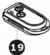
W-1 Wireless Remote
The wireless remote control system W-1 consists of a transmitter equipped with two buttons for fog on and off, and a receiver pre-attached to the rear panel of each W-series model.
* Transmitter:
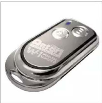
With the transmitter it is possible to emit fog via radio over a distance of up to 50 meters. The transmitter is compatible to any receiver of the W-series and can control an unlimited number of machines in parallel.
Press the button "A", to emit fog. The button "A" has the same function as the button VOLUME on the control panel, i.e. the fog output depends on the setting of menu item Volume Output . The display indicates Volume followed by the defined value or NONSTOPBURST when continuous fog output was selected. As additional control, the blue LED light. To stop the fog output, press the button "B".
* Receiver:
The receiver is tested and pre-attached to the rear panel of each W-series model. Please do not try to remove it. The receiver responds to up to 5 different transmitters that are registered with the machine. The included transmitter has been registered to the machine before shipment. It can be directly operated without any start-up setting.
- Registering transmitters
To operate the machine with a different transmitter than the included one, or to operate it with up to 5 different transmitters, each transmitter must be registered first. For this purpose, turn on the machine. When the display indicates » Wireless Detect...«, press the button "A" 1 second on each transmitter. Thus the previous transmitters are cleared from the memory of the receiver. The setting must be completed within 15 seconds at indication » Wireless Detect...«.
If no transmitter is registered when the machine is switched on, the memory of the receiver will keep the record of the previous operation.
Setting Example 1:
In order to register several transmitters with a machine, turn on the machine. When the display indicates « Wireless Detect...«, press the button “A”1 second on each transmitter within 15 seconds to establish the signal transmission.
Setting Example 2:
In order to use 1 transmitter to control 2 or more machines, turn on the machines at the same time. When the display indicates » Wireless Detect...«, press the button “A” 1 second on the transmitter within 15 seconds to establish the signal transmission.
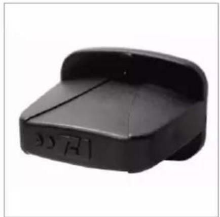
- Battery change on the transmitter
If the range of the transmitter decreases, the battery is probably exhausted and must be replaced. For this purpose, take off the housing cover and remove the used battery. Insert a fresh 12V battery, type 27A as indicated in the battery compartment and refit the housing cover.
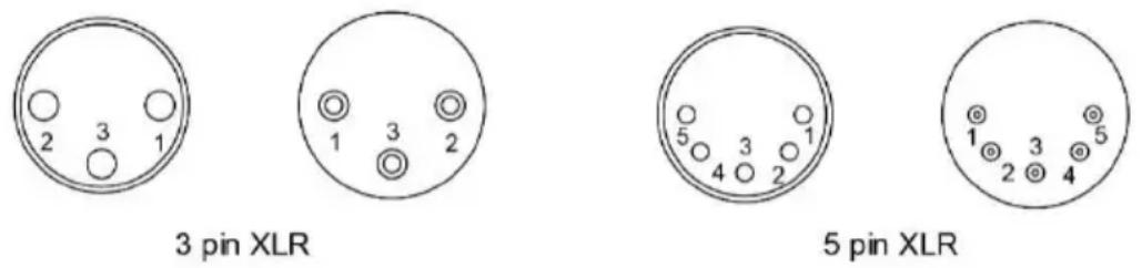
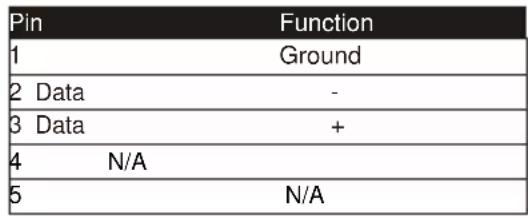
DMX Connector Pin Assignment
The machine provides 3 or 5 pin XLR connector for DMX connection. The diagram below indicates pin assignment information
DMX512 Settings
Channel A

0 - 5 = off (no output)
6 - 255 = output volume control (1 - 100 % output)
Both models are equipped with a DMX512 system. For connecting a DMX controller, 3-pin and 5-pin male-female XLR connections are provided at the back of each machine. The machines use one control channel for adjusting the output volume. The channel has a DMX value range of 0 to 255. After connecting a DMX controller, timer functions such as output duration and interval can be programmed using the DMX controller or the DMX control software. The machine cannot be controlled via the built-in control panel nor the W-1 wireless remote anymore. By using the DMX protocol, fog machines, lighting effects, and other special effects machines can be interconnected and easily controlled.
If channel A has a value from 0 to 5, the unit is off.
Between the values 6 to 255 the fog output volume is regulated. With 6 being the minimum output volume and 255 approaching the maximum output volume. The output volume rises as the DMX value is increased.
Note: If, for example, the machine is assigned to the DMX address 124, channel A corresponds to DMX address 124.
Note
If you experience low output, pump noise or no output at all, unplug immediately. Check the fluid level, the external fuse, the connection to the remote control, and power from the wall. If all of the above appears to be O.K., plug the unit in again. If fog does not come out after holding the remote button down for 30 seconds, check the hose attached to the tank to make sure there is fluid going through the hose. If you are unable to determine the cause of the problem, do not simply continue pushing the remote button, as this may damage the unit. Return the machine to your Antari dealer.
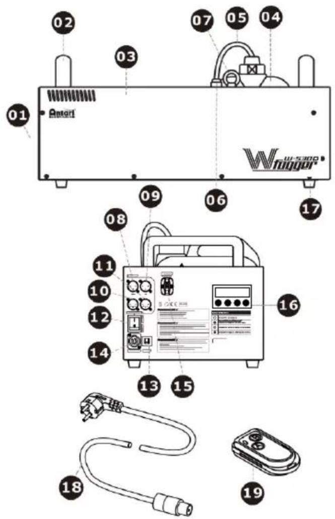
W-515D External View
01-Nozzle
02-Handle
03-Body
04-Tank &tank's cap
05-PUtube &filter
06-Tube adaptor
07-Safety ring
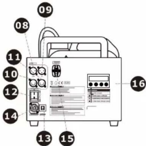
08-Control outlet socket (3 Pin XLR for DMX)
09-Control inlet socker (3 Pin XLR for DMX)
10-Control outlet socket (5 Pin XLR for DMX)
11-Control inlet socket
(5 Pin XLR for DMX)
12-Rocker switch / Power
13-Circuit breaker
14-Power socket
15-W-1 wireless receiver / W-DMX receiver
16-Control panel
17-Foot
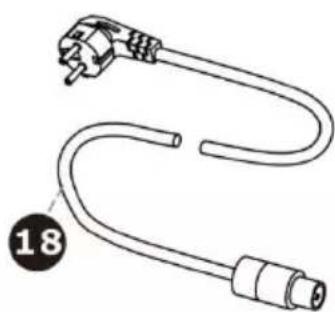
18-Power cord
19-W-1 wireless transmitter
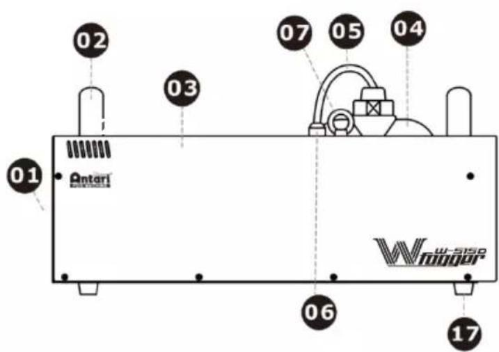
W-530D External View
01-Nozzle
02-Handle
03-Body
04-Tank & tank's cap
05-PU tube & filter
06-Tube adaptor
07-Safety ring
08-Control outlet socket (3 Pin XLR for DMX)
09-Control inlet socker (3 Pin XLR for DMX)
10-Control outlet socket (5 Pin XLR for DMX)
11-Control inlet socket (5 Pin XLR for DMX)
12-Rocker switch / Power
13-Circuit breaker
14-Power socket
15-W-1 wireless receiver / W-DMX receiver
16-Control panel
17-Foot
18-Power cord
19-W-1 wireless transmitter
Performance Note
All fog machines develop condensation around the output nozzle. Because this may result in some moisture accumulation on the surface below the output nozzle, consider this condensation when installing your unit.
All fog machines may sputter small amounts of fog occasionally during operation and for a minute or so after being turned off.
All fog machines have a recycling period after long bursts when the machine will shut itself down for a short period in order to heat up again. During this time no fog can be produced.
Cleaning and Storage
Do not allow the fog liquid to become contaminated. Always replace the cap on the fog liquid container and the fog machine liquid tank immediately after filling. Cleaning your fog machine regularly can help you to reduce the frequency of parts replacement and maintenance costs. After every 40 hours of continuous
operation, it is recommended to use distilled water to clean the heater according to the steps below.
The recommended cleaning regimen is as follows:
- Fill properly distilled water into a clean tank and connect the fluid tube of the fog machine to the tank.
- Run the unit in a well-ventilated area until the tank is almost empty.
- Use dry a cloth to wipe the fog machine. Cleaning is now complete. Refill with fog liquid. Run the machine briefly to clear any remaining liquid from the pump and heater.
Note: All fog machines are prone to clogging due to the thick consistency of fog liquid and the high temperature at which it vaporizes. However, a properly maintained fog machine should provide years of reliable use.
Clean with a dry cloth only. Store dry.
If the fog machine is not in use, please clean it before storage. Store the fog machine in a dry and cool place. Operate the fog machine at least once a month. A test-run consists of warming-up the machine followed by a few minutes of fog emission.
Technical Specification
| Model | W-515D | W-530D |
| Input voltage | US model : AC 100-120V, 50/60HZ 9A EU model : AC 220-240V, 50/60Hz 4.5A | EU model : AC 220-240V, 50/60Hz 4.5A |
| Rated power | 1500W | 2570W |
| Warm-up time | 10 minutes (approx.) | 12 minutes (approx.) |
| Fluid consumption | 100 ml/min | 160 ml/min |
| Fluid tank capacity | 6 Liters (1.59gal) | 6 Liters (1.59gal) |
| Compatible fluid | Antari FLG Heavy Fog Fluid | Antari FLG Heavy Fog Fluid |
| Antari FLR Light Fog Fluid | Antari FLR Light Fog Fluid | |
| Ambient temp. range | 0°C - 40 °C (32°F-104 °F) | 0 °C - 40 °C (32 °F-104 °F) |
| Control | DMX512, Timer, Manual, Wireless, Wireless DMX | DMX512, Timer, Manual, Wireless, Wireless DMX |
| DMX channels | 1 channel | 1 channel |
| Connection | Neutrik Powercon (Power) | Neutrik Powercon (Power) |
| XLR 3-pin and 5-pin (DMX) | XLR 3-pin and 5-pin (DMX) | |
| Optional accessories | FX-5 Flightcase | FX-5 Flightcase |
| W-515-HB Hanging Bracket | W-515-HB Hanging Bracket | |
| Dimension | L561 W278 H265 mm | L581 W278 H265 mm |
| (L22.09 W10.94 H10.43 inch) | (L22.87 W10.94 H10.43 inch) | |
| Weight | 14.5 kg (31.97 lbs) | 19.1 kg (42.11 lbs) |
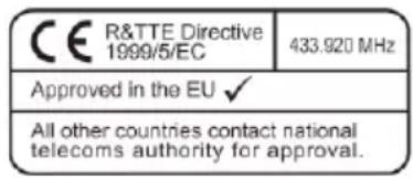
Approval
This product is in accordance with the R&TTE directive (Radio and Telecommunication Technical Equipment) of the European Union and falls into equipment Class 1. In all EU member countries, the operation of this wireless system is generally approved by the national telecom regulatory authority. The system is license-free. In some countries outside the EU, the operation of this wireless system may needs to be approved by the national telecoms regulatory authority.
Warranty
Warranty shall be valid only if the product is purchased from Antari's authorized distributors or dealers. For warranty service, send the product only to an authorized distributor or dealer.
All warranties are voided if the product has been modified in any manner; if the product has been repaired or serviced by unauthorized personnel; or the product is damaged due to improper use or maintenance as set forth in the instruction manual.
This is not a service contract and does not include standard maintenance or cleaning. All expendables are not covered by this warranty.
Additional warranties provided at the discretion of the distributor dealers shall remain the sole obligation of the distributor or dealer.
Always quote the unit's serial number and model name when contacting your distributor for information or assistance.
Please read and save these instructions.

Bedienungsanleitung
W-515D & W-530D Nebelmaschine
Dé ballage & Inspection
W-515D É lémentsetBranchements
For current product information visit Antali at:www.antali.com For information requests please contact us at sales@antali.com


G5 Short guide
Pinout
| Pin number | Funcon | Comment |
| J1:1 | GND | |
| J1:2 | Data - / RxD | RxD if J3:12 is connected to 3.3V, internal pulldown |
| J1:3 | Data + / TxD | RxD if J3:12 is connected to 3.3V, internal pulldown |
| J1:4 | Funcon switch | Pull up to 3.3V internally |
| J1:5 | OEM LED | 3.3V when On |
| J1:6 | 5V, 5-15V, 5-26V | Depending on card model |
| J1:7 | GND | |
| J1:8 | 3.3V | Dierent compared to G4 |
| J1:9 | Recepon Indicator / Mode | Dierent compared to G4 |
| J1:10 | Direcon | For TRX cards |
J3 is only for cads with -SPI extension
| J3:1 | Reset | |
| J3:2 | RX_NOT_TX | Output, High as RX, low as TX |
| J3:3 | Reserved | N/C internal use |
| J3:4 | Reserved | N/C internal use |
| J3:5 | Slave IRQ | IRQ signal when radiocard is SPI slave, not implemented |
| J3:6 | Overlay CS | CS Signal for overlay, acve high |
| J3:7 | SLAVE CS | CS Signal when radiocard is SPI slave, not implemented |
| J3:8 | SCK | Serial Clock signal |
| J3:9 | MISO | Master In, Slave out signal |
| J3:10 | MOSI | Master Out, Slave in signal |
| J3:11 | RS485 DIR | Direcon for RS485 driver |
| J3:12 | RS485 DISABLE | Connect to 3.3V when internal RS485 driver should be turned o |
Information for migrating from G4 to G5
PLEASE NOTE:
Pin 6 can handle 5 to 15V input on all receiver cards A40895G5 and A40896G5SPI
Pin 6 can handle 5V input on following transceiver cards A40890G5 and A40891G5SPI
Pin 6 can handle 5 to 26V input on following transceiver cards A40890G5SP
Pin 8 can only be connected to 3.3V
- Connect only one power source to the card
- OEM LED output 3.3V when the LED should be on, adjust resistor to give enough current to the LED, maximum output current is 0.5mA
Pin 9 does not indicate MODE on the receiver, on receiver it is indicang recepon
- Shutdown voltage: To ensure stable operation, the voltage need to be according to the pinout list. But the card may be operational all the way down towards 1.5V, to ensure that the cards is disabled, power need to be reduced to 0V
Transceiver cards
IMPORTANT DMX direction for cards
All transceiver cards can operate as transmitter or receiver, by seng the voltage on pin 10 in the following 3 conguraons
| Pin 10 voltage | Funcon |
| GND | Transmier (like G4 type O cards) |
| 3.3V (Open) | Receiver (like G4 type O cards) |
| 1.65V | Transmier or receiver (like G4 type R cards) Direcon is fetched from non-volale storage; direcon is changed if the buon (pin 4) is connected to GND during power up To accomplish this, it is easiest to use two 4.7kOhm resistors, put one 4.7kOhm from pin 8 (3.3V) to pin 10 and one 4.7kOhm resistor from pin 7(GND) to pin 10. |
OEM LED indication
Transmitter card

On 900ms / O 100ms = no DMX present
Connuously On = DMX present
On 100ms / O 100ms = linking receivers
On 500ms / O500ms = unlinking all receivers
Receiver card
Connuously O = not assigned to a transmier
On 900ms / O100ms = assigned to a transmitter, but no DMX present
Connuously On = assigned to a transmier and DMX present
On 100ms / O 100ms = link to transmitter lost or linking to transmitter
Wireless Soluon Sweden AB Page 3(5)
Stureparksvagen 7 - 451 55 Uddevalla - Sweden
Tel: +46 522 511 511 Fax: +46 522 440 885
Wirelessdmx.com sales@wirelessdmx.com
MODE LED indication
Transmitter card
Connuously On = G4S mode
Connuously O = G3 mode
Receiver card
Aer a low pass Iter 1
The signal has a 1s period, that goes low in 100ms steps to indicate repepon rate:
100% recepton: High
90% recepon: 900ms high, 100ms low
60% recepon 600ms high, 400ms low
1) The low passIter should iter pulses that are up to 50 us long. Pin 9 can drive up to 0.5mA and for Iter purpose, there is a 330ohm resistor on the PCB between the driver and the pin.
There will be a pulse for each received radio package, if the pulse is high or low depends on the current signal level, there will be an error of up to 2 pulses for each second, so the error is negligible if the recepon is measured with pulse counting.
LED Overlay Interface, G5 cards For the G5 cards with SPI functionality (two pinheaders).
It is possible to implement a display interface similar to the one used on the W-DMX BlackBox/WhiteBox range.
The overlay interface consists of an SPI interface that shis out data for the LEDs as described below. To avoid icker a latched shi register is recommended.
The SPI speed is 2.5MHz and Overlay CS is pulled high before the output start and pulled low aer the SPI output has ended, SCK and MOSI is output signals.
LED order
| Name | Bit | Text | Color | Descripon |
| Power | 0 | PWR | Blue | Power, blinking in control mode |
| RDM | 1 | RDM | Green | RDM on/o |
| Green of Mode LED | 2 | Mode | Green | Mode indicator, part of a RGB LED |
| Red of Mode LED | 3 | Mode | Red | Mode indicator, part of a RGB LED |
| Blue of Mode LED | 4 | Mode | Blue | Mode indicator, part of a RGB LED |
| 2 Universe | 5 | UNIV | Green | Is receiving a 2 universe link |
| Link | 6 | LINK | Green | Link established |
| Data | 7 | DATA | Green | DMX Data present |
| Transmit Mode | 8 | TX | Green | Radio Transmier |
| Receive Mode | 9 | RX | Green | Radio Receiver |
| Reserved | 10 | |||
| Signal 1 | 11 | Red | Signal Strength | |
| Signal 2 | 12 | Yellow | Signal Strength | |
| Signal 3 | 13 | Green | Signal Strength | |
| Signal 4 | 14 | Green | Signal Strength | |
| Signal 5 | 15 | Green | Signal Strength | |