Sophia 88665 - Intercom GEV - Free user manual and instructions
Find the device manual for free Sophia 88665 GEV in PDF.
| Product Type | Video door phone for single-family home |
| Brand | GEV |
| Model | Sophia 88665 |
| Indoor Unit - Dimensions | 200 x 145 x 23 mm |
| Indoor Unit - Weight | 0.5 kg |
| Outdoor Unit - Dimensions | 95 x 140 x 43 mm |
| Outdoor Unit - Weight | 0.5 kg (with protection box) |
| Indoor Unit Power Supply | 17 V DC (via power adapter) |
| Outdoor Unit Power Supply | 12 V DC via indoor unit |
| Power Consumption (standby) | Max. 2 W (indoor unit) |
| Power Consumption (active) | Max. 14 W (indoor), max. 3 W (outdoor) |
| Screen | Large 7-inch LCD screen, LED backlight, resolution 1440 x 234 |
| Main Functions | Audio/video communication, monitoring, optional electric strike control, intercom between two indoor units, night vision (IR LED) |
| Melodies | 4 selectable melodies |
| Night / Silent Mode | Yes, disables ringtone |
| Camera Viewing Angle | 90° diagonal, 57.8° horizontal, 48.6° vertical |
| Sensor | Color CCD camera 1/3" Sony Super HAD, 290,000 pixels |
| Maximum Distance Between Units | 50 m (1.0 mm² wire), 100 m (1.5 mm² wire) |
| Indoor Operating Temperature | 0 to 40 °C |
| Outdoor Operating Temperature | -10 to 50 °C |
| Electric Strike Connection | 12 V DC / max. 1 A, dry contact |
| Maintenance | Clean with a damp cloth, do not use harsh chemicals |
| Installation | Must be performed by a specialist |
| Supplied Parts | Indoor unit, outdoor unit, wall bracket, weather protection box, 8 screws, 8 wall plugs, screwdriver, adapter cable |
Frequently Asked Questions - Sophia 88665 GEV
User questions about Sophia 88665 GEV
0 question about this device. Answer the ones you know or ask your own.
Ask a new question about this device
Download the instructions for your Intercom in PDF format for free! Find your manual Sophia 88665 - GEV and take your electronic device back in hand. On this page are published all the documents necessary for the use of your device. Sophia 88665 by GEV.
USER MANUAL Sophia 88665 GEV
text_image
Technical diagram of a device with numbered components and internal structure annotationsFig. 3
natural_image
Technical diagram of a device front panel with labeled points A and B, showing internal components like buttons, gauges, and circular features (no text or symbols beyond labels)natural_image
Technical line drawing showing installation of a wall-mounted device with mounting brackets and a monitor on the right (no text or symbols)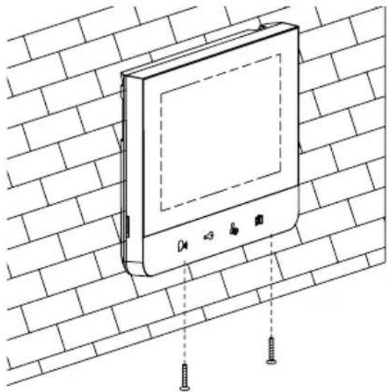
natural_image
Line drawing of a wall-mounted electronic device mounted on a brick wall, with screw fasteners inserted (no text or symbols)natural_image
Technical line drawing of a mechanical device with two vertical rods and a central housing (no text or symbols)B
natural_image
Technical line drawing of a mechanical device with internal components (no text or symbols)C
natural_image
Technical line drawing of a device casing with two handles inserted (no text or symbols)D

natural_image
Technical line drawing of a device casing with internal components (no text or symbols)
text_image
E SOPHIA F SOPHIAtext_image
Technical diagram showing a wall-mounted electrical component with labeled parts and cross-sectional view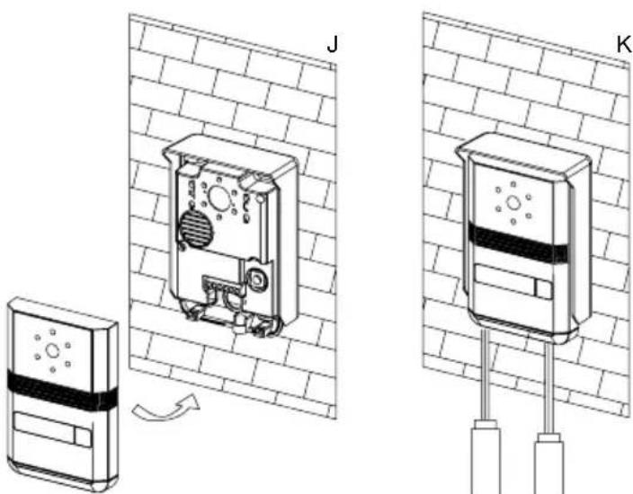
text_image
Technical diagram showing two views (J and K) of a device mounted on a wall, with a sensor device and directional arrow indicating rotation.Single-dwelling building video door intercom SOPHIA 88665
Safety & Operating Instructions
These instructions are for your safety. Please read through them thoroughly before use and retain for future reference. We recommend this equipment is installed by a competent electrician.
Parts Supplied
Description Qty
Indoor Monitor 1
Outdoor Camera 1
Wall mounting bracket 1
Power Adaptor 1
Fittings Supplied
Description Qty
Screw 8
Wall plug 8
Wrench 1
Adapter Cables 1
Before You Start
- Check the accessory and make sure you have all of the parts listed above included. If not, contact your local store or your vendor for assistance.
- This video door phone set is composed of a monitor with its power adaptor and an outdoor unit. t. It allows communicating with the visitor who calls at the door and controlling the opening of the door and/or gate. You can develop your own installation by adding an optional/additional monitor(s) and/or a second outdoor unit. For
a safe installation and use,
please read carefully these
instructions and keep them safe.
Safety Instructions
All warranty claims will be null and void in the event of any damage or loss caused by failure to observe these operating instructions. We accept no liability for any consequential losses or damage. We accept no liability for any personal injury or material damage caused by improper use or by failure to observe the safety advice. In these cases the guarantee and warranty are invalidated. For safety and authorization purposes it is not permitted to carry out any adaptation or conversion of the device.
-
Do not install near other electronic equipment such as computers, TV, video recorder as this may cause radiated interference to the unit.
-
Do not disassemble the unit.
-
Do not spray water on the indoor unit. Do not keep the outdoor unit where it will be exposed to extreme moisture.
-
Do not overload mains wall outlets or extension cords.
-
Do not drop or shock the unit.
-
Remove the power cord from the wall socket when unit is not used for long periods.
-
Do not place any naked flames (e.g. lighted candles) on the apparatus.
-
Do not place objects filled with water (e.g. vases) on the apparatus.
-
Do not cover the ventilation holes with clothing, paper, curtains etc.
-
This apparatus is designed for moderate climates. Do not use in high humidity, dusty or dirty areas.
-
To disconnect or isolate the unit, switch off at the socket or remove plug from wall socket. Please ensure the plug and socket is easily accessible.
Warnings
-
Do not install the outdoor unit where it will be exposed to direct sunlight or any strong reflected light. Avoid extremely bright locations for the indoor unit as the monitor screen image will be adversely affected.
-
Do not install the outdoor unit where it will be subjected to extremes of dust or moisture.
-
Do not install the outdoor unit where it will be exposed to rain.
-
Do not install near acid oxides, ammonia, or any harmful gas (it might cause malfunction).
-
Do not install the outdoor unit in a location where the
lens filter is likely to get scratched or very dusty.
- Check cables are connected correctly and camera unit is firmly installed.
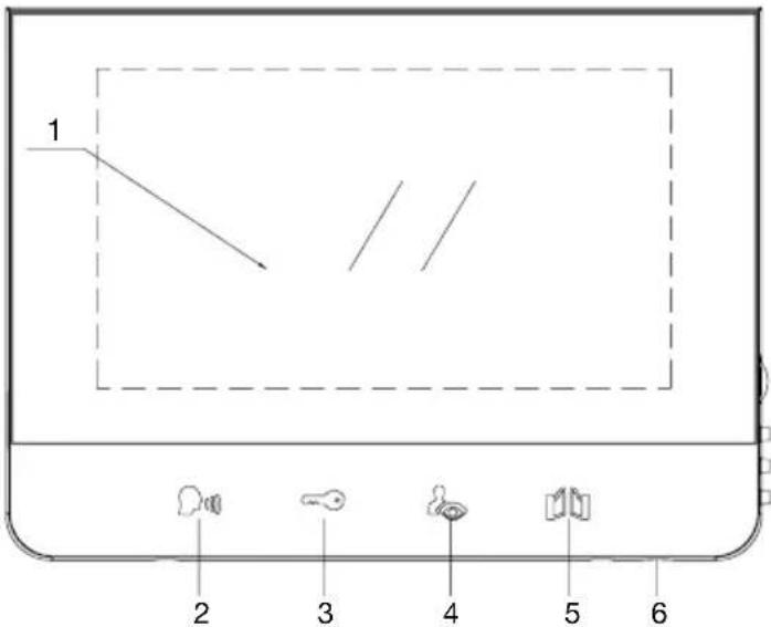
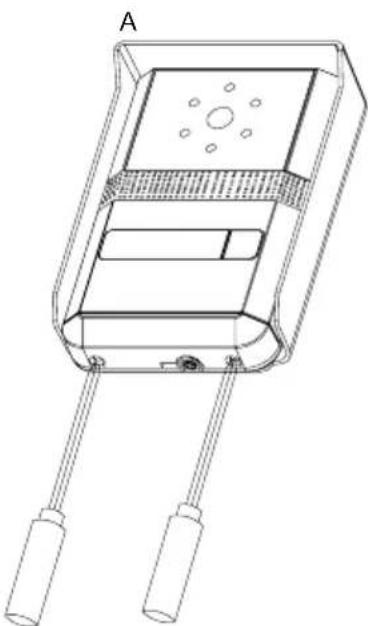
Indoor unit (Fig. 1)
text_image
1 2 3 4 5 6-
Monitor screen
-
Talk on/Talk off
(Monitor off)
-
Door lock Open
-
Camera 1 / Camera 2
(Surveillance Mode)
-
Gate Open Button
-
Microphone
-
Menu Select
(Brightness, Contrast, Colour)
-
Down
-
Up
-
Ring Sound volume

text_image
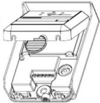
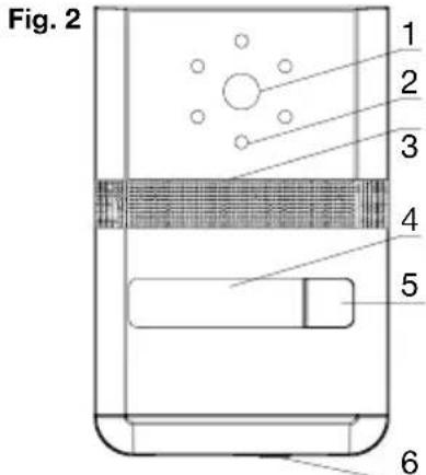
Technical diagram of a device with labeled components, including a 3D panel and a vertical panel with numbered parts.Outdoor unit
-
Camera lens
-
IR-LEDs for night vision
-
Speaker
-
Name Plate
-
Call Button
-
Microphone
text_image
Fig. 2 1 2 3 4 5 6Fig. 3

natural_image
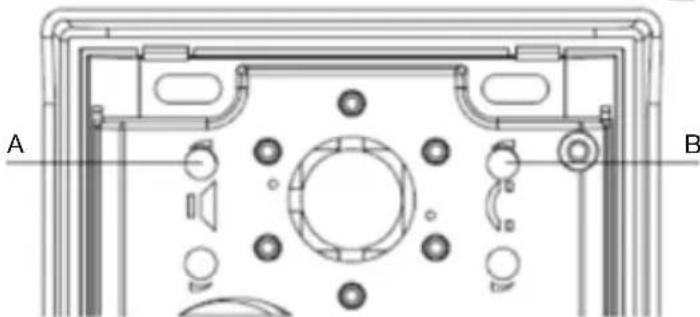
Technical diagram of a device front panel with labeled points A and B, showing internal components like buttons, gauges, and circular elements (no text or symbols beyond labels)A left knob - adjust sound level of the outdoor unit's speaker.
B right knob - adjust sound level of the speaker's monitor.
Assembly instructions
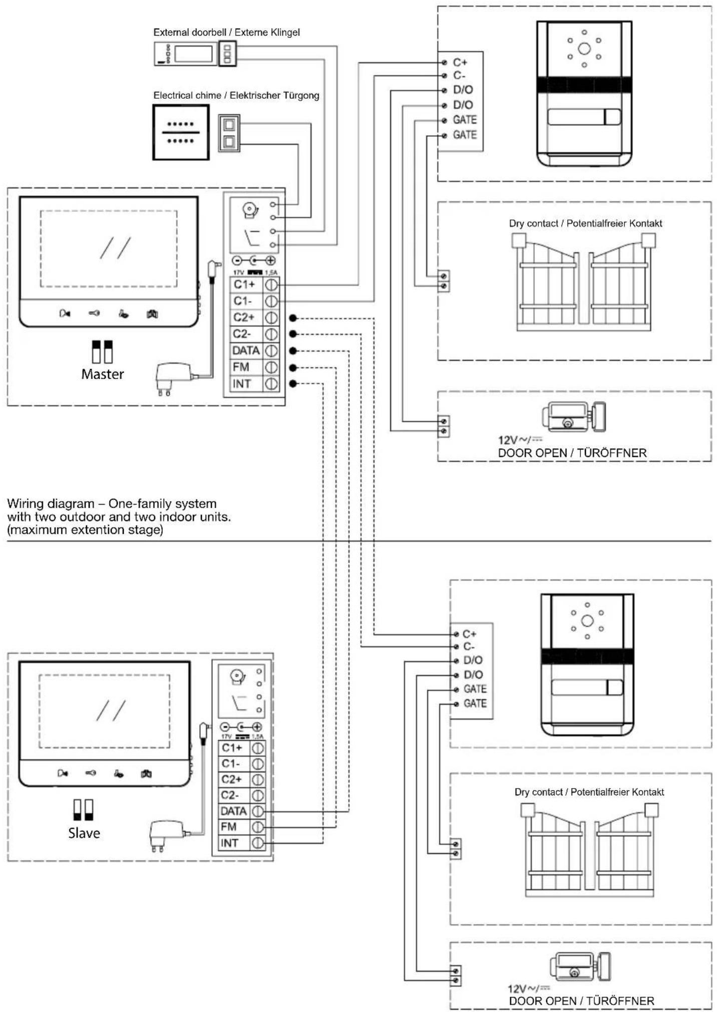
Wiring diagram – One-family system with one outdoor and one indoor unit.
flowchart
graph TD
    A["Master"] --> B["Electrical chime / Elektrischer Türgong"]
    B --> C["External doorbell / Externe Klingel"]
    B --> D["17V 1.5A"]
    D --> E["C1+"]
    D --> F["C1-"]
    D --> G["C2+"]
    D --> H["C2-"]
    D --> I["DATA"]
    D --> J["FM"]
    D --> K["INT"]
    E --> L["C+"]
    E --> M["C-"]
    E --> N["D/O"]
    E --> O["D/O"]
    E --> P["GATE"]
    E --> Q["GATE"]
    R["12V~/= DOOR OPEN / TÜRÖFFNER"] --> S["Dry contact / Potentialfreier Kontakt"]
    R --> T["12V~/= DOOR OPEN / TÜRÖFFNER"]
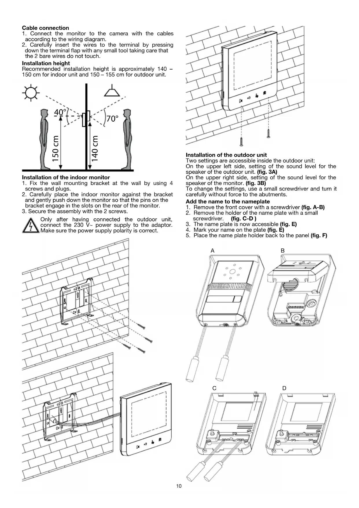
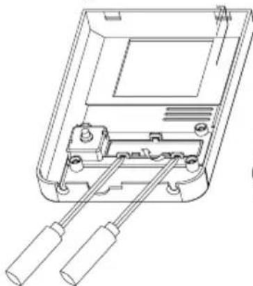
Cable connection
- Connect the monitor to the camera with the cables according to the wiring diagram.
- Carefully insert the wires to the terminal by pressing down the terminal flap with any small tool taking care that the 2 bare wires do not touch.
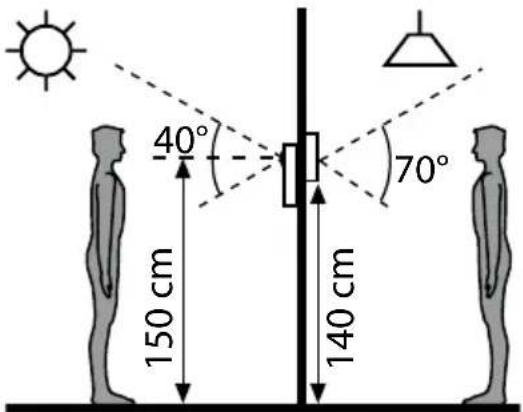
Installation height
Recommended installation height is approximately 140 - 150 cm for indoor unit and 150 - 155 cm for outdoor unit.
text_image
40° 70° 150 cm 140 cmInstallation of the indoor monitor
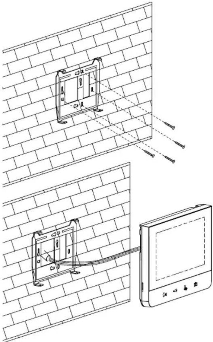
- Fix the wall mounting bracket at the wall by using 4 screws and plugs.
- Carefully place the indoor monitor against the bracket and gently push down the monitor so that the pins on the bracket engage in the slots on the rear of the monitor.
- Secure the assembly with the 2 screws.

Only after having connected the outdoor unit, connect the 230 V\~ power supply to the adaptor. Make sure the power supply polarity is correct.
natural_image
Technical line drawing showing a wall-mounted device with internal components and a close-up of its screen (no text or symbols present)
natural_image
Line drawing of a wall-mounted electronic device mounted on a brick wall, with screw fasteners inserted (no text or symbols)Installation of the outdoor unit
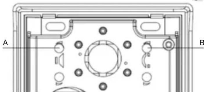
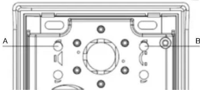
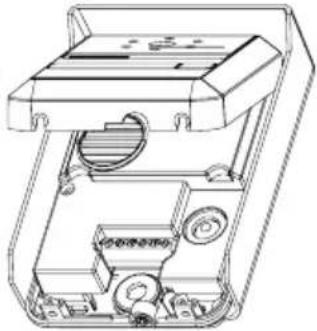
Two settings are accessible inside the outdoor unit: On the upper left side, setting of the sound level for the speaker of the outdoor unit. (fig. 3A) On the upper right side, setting of the sound level for the speaker of the monitor. (fig. 3B) To change the settings, use a small screwdriver and turn it carefully without force to the abutments.
Add the name to the nameplate
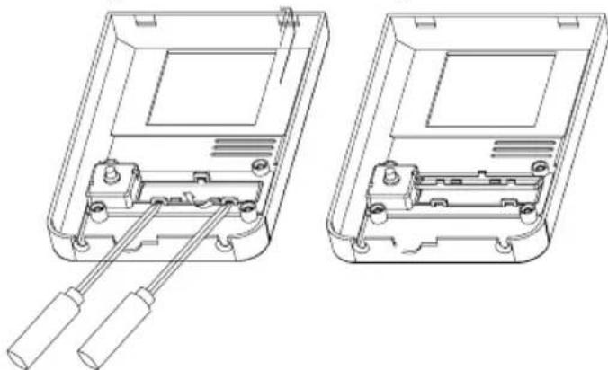
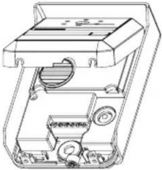
- Remove the front cover with a screwdriver (fig. A-B)
- Remove the holder of the name plate with a small screwdriver. (fig. C-D)
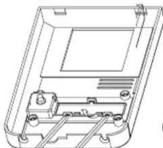
- The name plate is now accessible (fig. E)
- Mark your name on the plate (fig. E)
- Place the name plate holder back to the panel (fig. F)
natural_image
Technical line drawing of a rectangular electronic device with two leads and a central panel (no text or symbols)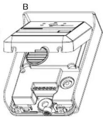
natural_image
Technical line drawing of a mechanical device with internal components (no text or symbols)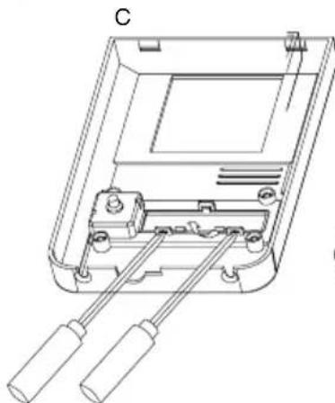
natural_image
Technical line drawing of a device casing with two handles and internal components (no text or symbols)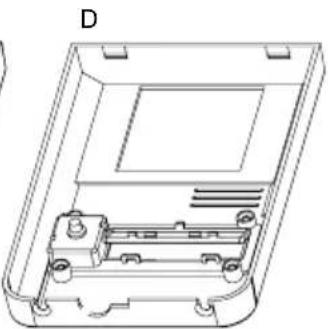
natural_image
Technical line drawing of a device casing with internal components and mounting holes (no text or symbols)
text_image
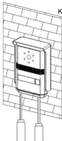
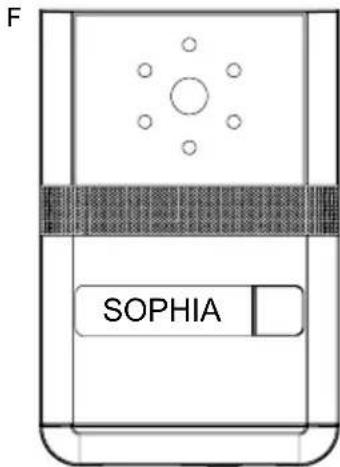
F SOPHIAMounting the outdoor unit
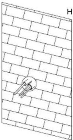
1) Mount the outdoor unit on the wall by using four mounting screws and wall plugs. (fig. H-I)
2) Replace the front cover and security it by replacing the 2 screws at the bottom of the camera. (fig. J-K)
natural_image
Diagram of a brick wall with a circular component embedded in it, labeled 'H' at the top (no text or symbols on the diagram itself)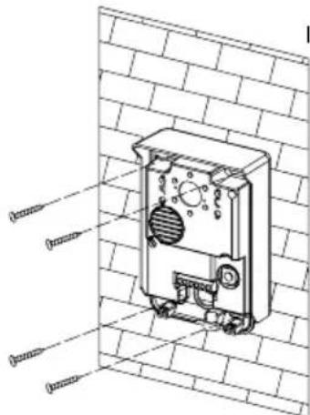
natural_image
Technical line drawing of a mechanical device mounted on a brick wall, with no visible text or symbols.
natural_image
Technical illustration of a wall-mounted device with a mounted panel and directional arrow (no text or symbols)
natural_image
Technical line drawing of a wall-mounted device with two vertical posts and a central display (no text or symbols)Do not put screws into the microphone hole. Do not point the video camera directly at the sun or at reflecting surfaces.
Tip: we recommend passing the cables through a protective sleeve to shield them from impacts and weather influences.
Cable connection
Connect the monitor(s) to the outdoor unit(s) and the (optional) door opener with the cables according to the wiring diagram. Carefully insert the wires to the terminals with any small tool taking care that two bare wires do not touch. Make absolutely sure that no bare wires are touching each other after the connection!
(Optional) installation of a door opener
This video doorbell features the option to implement an electrical door opener. This allows you to remotely open a door by pressing the button. For wiring please refer to the diagrams.
Important: it is essential that the electric latch or lock installed has a mechanical memory. We therefore recommend GEV's door opener order no. 07680 or order no. 07697
(Optional) installation of a DIN rail transformer instead of a power adaptor
In case you haven't a power socket close enough near by the indoor unit or you have the opportunity to connect with your house installation, there's the option to replace supplied power adaptor by a DIN rail-adaptor (not included / separately available GEV order. no. 08834402). For installing the DIN-rail adaptor follow the instructions that come along with it.
(Optional) installation of a floor bell and/or an electronical door chime
This unit features several options of adding accessories like an additional door chime or an extra call button (floor bell).
You can either install individually one of the above mentioned accessories or both at the same time.
The floor bell button connection option gives you the freedom of choice to place an additional doorbell button wherever you want. E. g. directly in front of your door or, at a back entrance, etc..
The option for adding an electronical door chime (speaker) allows you to place an external door (chime besides the one built in the indoor unit. In case the built in indoors unit's door chime is not loud enough or too far away you can add an electronical door chime and freely place it wherever required.
Connect the accessory according to the wiring diagram.
Performance Settings
You can adjust the brightness, contrast and colour of the monitor when it is ON by pressing the Menu button (fig. 1) at the side of the monitor.
Press the Menu button- then the brightness, contrast and colour indication will appear. Select the setting you want to adjust by pressing the Up and Down buttons, then press the Menu button again to confirm the selection and then press the Up and Down buttons to adjust. Finally, press the Menu button to confirm the setting.
Operating Instructions
The touch keys must be handled by slightly touching with the fingers.
- Incoming call
When the call button on the outside camera unit is pressed, the indoor unit chime rings and the visitor's picture will appear on the indoor monitor. After the visitor is visually identified, and you wish to talk with the visitor, touch the button. The unit will remain activated for approximately 60 seconds before it automatically shuts off. To re-activate for continued conversation, touch the button and then touch the button.
- Activation of outside unit from monitor unit (Surveillance Mode)
a) Touch the button of the indoor unit at any time and the outdoor camera will be activated and show the external view.
b) If you have installed two cameras, touch this button to change from camera one to another.
If you press twice the button, that the camera is not connected, you have a black screen and a noisy sound. After 1 second the video of the main camera reappears.
- Operating time
a) Call time: Approximately 30 seconds.
The picture terminates automatically if indoor unit is not answered within approximately 30 seconds after the call button of the outdoor camera unit is touched.
b) Talk time: Approximately 60 seconds
When monitor unit is called by the outdoor unit and the monitor is answered, there is approximately 60 seconds of time available before the unit
automatically shuts off.
c) Monitor time: Approximately 30 seconds
When outside camera is activated from the inside, there is approximately 30 seconds of viewing time before the unit automatically shuts off.
- Activation of "Intercom" button
An intercom calling can be started by any indoor monitor when it is on standby mode.
When the intercom button 📁 on either indoor monitor is touched, this will ring all monitors in a system. You can talk with the calling monitor by touching the 📁 button on the second monitor. Touch 📁 for shutting of again. There is approximately 60 seconds of time before the unit automatically shuts off.
- Activation of button
Door open:
If an electrical lock or door strike is added to the installation, connect it to the terminals at the back of the roadside panel.
If you want to open the door to let the caller in, just touch the button on the indoor monitor.
This function can only be used when the screen is switched on. It is normal that the image switches off one moment following the control of the door open.
Important: It is essential that the electric latch or lock installed has a mechanical memory.
- Activation of button
Gate open:
Connect the gate opener directly to the terminals at the back of the roadside panel which supplies a current-free "dry" contact to connect to the "push button" control of your automatic gate opener.
If you want to open the gate to let the caller in, just touch the 📁 button on the indoor monitor.
This function can only be used when the screen is switched on. It is normal that the image switches off one moment following the control of the gate opener.
- Change the melody
At standby mode, touch the button, you can hear the melody. Then touch to choose your desired melody. There are 4 melodies available. To confirm the melody of your choice, touch button again.
- Mute on/Mute off / Night Modus / Silent Modus
At standby mode, touch the button, the pictogram shifts from blue to red. When the monitor's status is Mute on, there will be no melody, while other functions will be normal. To reactivate the ring tone, touch button, the pictogram shifts from red to blue.
Extending your system/ Cofiguring your system
Thisy system can be extendend in several ways- e. g. by adding more indoor or outdoor units. Please refer to the wiring diagrams for installation. Please take not of the jumper settings in the wiring diagrams. It is essential that you adopt the Jumper settings according to the information in the diagrams.
The jumpers are to be found on the backside of the indoor unit and are marked with the letters M (Master) and S (Slave). Both Jumper up mean Master unit, both jumpers down mean slave unit.
Care and Maintenance
- Do not store in hot or cold areas. Extreme hot or cold temperatures can shorten the life of electronic devices and can distort/melt certain plastics or may cause malfunction.
- Dropping can result in failure to operate. Circuit boards can crack and may not survive the impact.
- Do not use or store in areas of high levels of dirt or dust. The electronics may be contaminated. Any moving parts will wear prematurely.
- Do not use harsh chemicals, cleaning solvents or strong detergents. To clean, wipe with a damp cloth from time to time.
Recycling Instructions
Waste electrical products should not be disposed of with household waste. Please recycle where facilities exist. Check with your Local Authority or retailer for recycling advice.
Troubleshooting – Practical tips
| Problem | Possible Solution |
| No power (no picture on monitor) | Is the AC plug firmly inserted into the AC outlet? |
| Power is on, but no image on the monitor | Is the cable firmly connected between the monitor and the camera?Is the polarity of wires correct between the outdoor unit and indoor monitor unit? |
| The picture is too dark or too white | Adjust brightness control |
| Chime sound is too low | Adjust the volume control |
| Outdoor unit's speaker sound level too loud/ silent | Fig. 3A: left knob: adjust sound level of the outdoor unit's speaker. |
| Sound level of the monitor's speaker is to low | Fig. 3B: right knob: adjust sound level of the speaker's monitor. |
Technical data
Indoor Unit Specifications
Dimensions W 200 mm x H 145 mm x D 23 mm
Weight 0.5 Kg
Input Power DC17 V (External Power Supply)
Power Consumption Idle mode: 2 W, Operating: Max. 14 W
Connecting System 2 wires, 2 cameras, 2 monitors
Call sound Chime sound
Max. Distance & wiring Monitor to camera, 50 m: 1.0 mm
Master to slave 20 m: 1.5 mm
Display 7 Inch Digital wide screen LCD (LED Backlight)
Resolution 1440 H x 234 V
Operating Temperature 0 \~ 40°
^2 wire, 100 m: 1.5 mm ^2 wire,
^2 wire, Door lock to camera 20 m: 1.5 mm ^2 wire
| Outdoor Unit | Specifications | |
| Dimensions | W | 95 mm x H 140 mm x D 43 mm |
| Weight 0.5 Kg (w/rain shield) | ||
| Input Power DC12 V from monitor | ||
| Power Consumption Max. 3 W | ||
| Aspect Material | Zinc alloy die casting with painting finish | |
| Wiring | Monitor: 2 wires, door lock: 2 wires | |
| Image sensor | 1/3" Colour Sony Super HAD CCD Camera | |
| Resolution 420 TV Lines | ||
| Video output | Composite video signal 1 Vp-p at 75 Ohm terminated | |
| Pixels | 290.000 pixels | |
| Iris | Electronic auto iris | |
| Lighting | IR-LED | |
| Viewing Angle | Diagonal: 90° horizontal: 57.8° vertical: 48.6° | |
| Lens | 3.7 mm flat pin hole lens | |
| Door lock | 2 terminals with DC power output 12 V/max. 1 A | |
| Mounting type | Surface mount | |
| Operating Temperature -10°C ~ 50°C | ||
text_image
Technical diagram of a device with numbered components and internal structure annotationsFig. 3

natural_image
Technical diagram of a device front panel with labeled sections A and B, showing internal components like buttons, gauges, and circular elements (no text or symbols beyond labels)natural_image
Technical line drawing showing a wall-mounted device connected to a tablet via cable, with no visible text or symbols.
natural_image
Line drawing of a wall-mounted electronic device mounted on a brick wall, with screw fasteners inserted (no text or symbols)natural_image
Technical line drawings of two electronic device components labeled A and B, showing internal wiring and housing (no text or symbols present)C
natural_image
Technical line drawing of two open electronic device casing components with internal wiring and mounting holes (no text or symbols)D


text_image
F SOPHIAnatural_image
Diagram of a brick wall with a circular object embedded in it, labeled 'H' at the top (no text or symbols on the diagram itself)
text_image
Technical diagram of an electrical component with labeled parts, shown in 3D view against a brick wall background.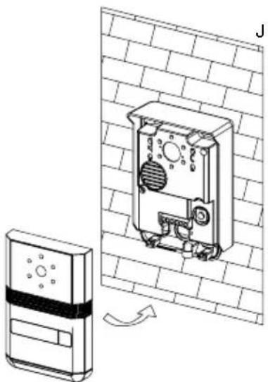
natural_image
Technical line drawing of a wall-mounted electronic device with a mounted panel and a separate sensor device (no text or symbols)
natural_image
Technical line drawing of a mounted security camera mounted on a brick wall (no text or symbols)text_image
Technical diagram of a device with numbered components, including a vertical panel and a side-view view.Fig. 2
Unità esterna
text_image
Technical diagram of a device with numbered components and internal structure annotationsFig. 3
natural_image
Technical diagram of a device rear panel with labeled components (A and B), showing internal components like buttons, gauges, and circular elements (no text or symbols beyond labels)natural_image
Technical line drawing showing installation of a wall-mounted device connected to a monitor, with no visible text or symbols.
natural_image
Line drawing of a wall-mounted electronic device mounted on a brick wall, with screw fasteners inserted (no text or symbols)natural_image
Technical line drawing of a mechanical device with two vertical rods and a central housing (no text or symbols)C
B
natural_image
Technical line drawing of a mechanical device with internal components (no text or symbols)D
natural_image
Technical line drawing of a device casing with internal components and mounting holes (no text or symbols)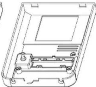
natural_image
Technical line drawing of a device casing with internal components (no text or symbols)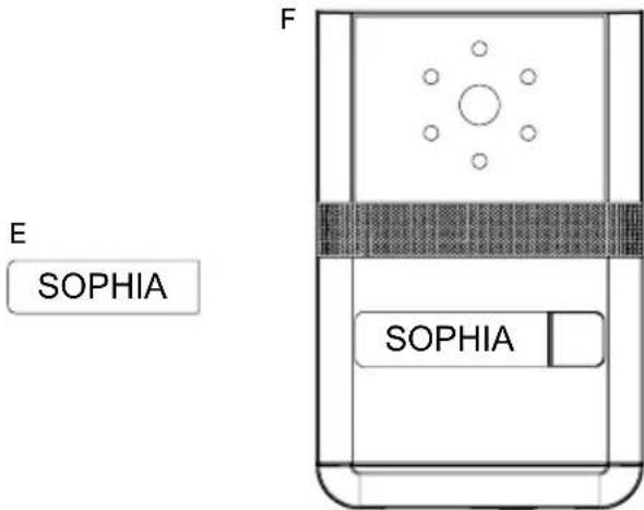
text_image
E SOPHIA F SOPHIAtext_image
Technical diagram showing a wall-mounted electrical component with labeled parts, including a key and a device inside a housing.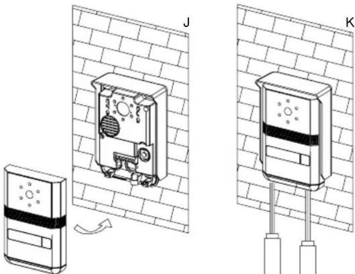
natural_image
Technical illustration of two wall-mounted electronic devices labeled J and K, showing internal components and wiring connections (no text or symbols beyond labels)text_image
Technical diagram of a device with numbered components, including a vertical panel and a side view with labeled parts.Moduł zewnętrzny
llustr. 2
text_image
Technical diagram of a device with numbered components and internal structure annotationsllustr. 3
natural_image
Technical diagram of a device front panel with labeled points A and B, showing internal components like buttons, gauges, and circular elements (no text or symbols beyond labels)natural_image
Technical line drawing showing a wall-mounted device connected to a tablet, with no visible text or symbols.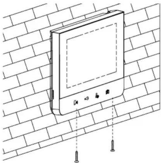
natural_image
Line drawing of a wall-mounted electronic device mounted on a brick wall, with screw fasteners inserted (no text or symbols)natural_image
Technical line drawing of a mechanical device with two vertical rods and a central housing (no text or symbols)B
natural_image
Technical line drawing of a mechanical device with internal components (no text or symbols)C

natural_image
Technical line drawing of a device casing with two handles inserted (no text or symbols)D

natural_image
Technical line drawing of an open electronic device casing with internal components (no text or symbols)
text_image
E SOPHIA F SOPHIAnatural_image
Diagram of a brick wall with a circular object embedded in it, no text or symbols present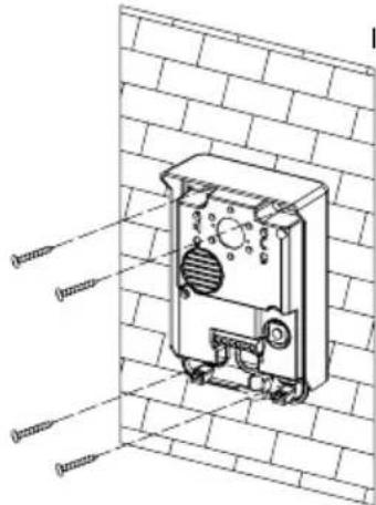
text_image
Technical diagram of a mechanical device with labeled components, shown in 3D view against a brick wall background.
natural_image
Technical line drawing of a wall-mounted device with a sensor array and a separate sensor unit (no text or symbols)