CVF 86012 - Intercom GEV - Free user manual and instructions
Find the device manual for free CVF 86012 GEV in PDF.

User questions about CVF 86012 GEV
0 question about this device. Answer the ones you know or ask your own.
Ask a new question about this device
Download the instructions for your Intercom in PDF format for free! Find your manual CVF 86012 - GEV and take your electronic device back in hand. On this page are published all the documents necessary for the use of your device. CVF 86012 by GEV.
USER MANUAL CVF 86012 GEV
natural_image
Illustration of two remote devices, one with a control panel and the other showing a smiling face on a screen (no text or symbols on device body)

Typ: CVF
# 086012
B
text_image
1 2 3 4 5 6 7 1 3 5 6 2 4 7 9-12V NC C NOC
text_image
C 1 6 7 2 8 3 4 9 10 5
text_image
11 12 13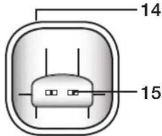
text_image
14 15D
natural_image
Diagram of a remote control panel with battery and indicator lights, showing no text or symbolsD1
text_image
D1 13.5Ω 62.4.7 DC 9-12V NC C NO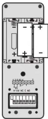
text_image
1.3.5.62.4 * DC 9-12V NC C No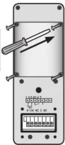
text_image
1:3.5 82.4.7 DC 9-12V NC C ND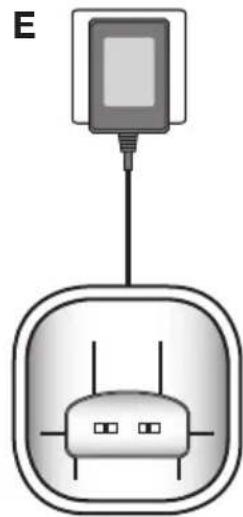
natural_image
Diagram of a device with a cable and two ports, no text or symbols presentF
text_image
40° 70° 150 cm 140 cm1
natural_image
Technical illustration of a mechanical bracket mounted on a brick wall, with three screws inserted (no text or symbols present)2
natural_image
Mechanical assembly diagram showing a pin inserted into a housing with a handle, labeled '3' (no text or symbols on the diagram itself)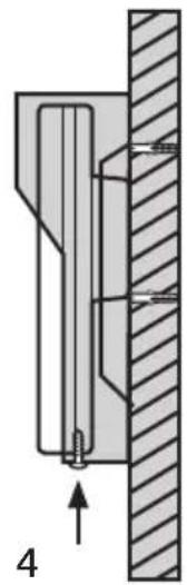
natural_image
Mechanical assembly diagram showing a piston and shaft assembly (no text or labels)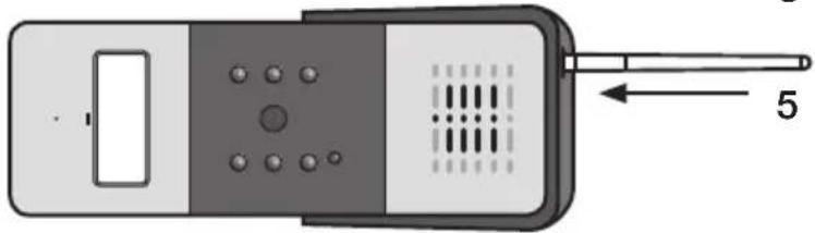
natural_image
Diagram of a handheld device with ports and a pointer, no text or symbols presentG
text_image
1356247 9-12V NC C NO DC Power +9~12V GND G1 1356247 +9~12V GND COM NO + DC Power for Lock G2G3 - + - LockH
text_image
Diagram showing wireless signal transmission between two remote devices with icons and labels|
text_image
1 # MonitorRegister 2 #Schnappschuss-Diashow
Please read before use
Congratulations on purchasing this high-quality GEV product. Please read these operating instructions carefully before installing your system and follow the instructions provided.
Safety precautions
Please follow these basic safety rules before using the device to avoid the risk of electric shock or injury.
- Read these operating instructions carefully and follow the instructions provided.
- Pay attention to the hazard warnings marked on the device.
- The time and date need to be reset whenever the batteries are replaced.
- Always unplug the device before cleaning it with a damp cloth. Do not use liquid detergents or cleaning sprays.
- Keep the mains cable free from any objects that could damage it.
- Do not install the outdoor unit near any metal objects.
- Make sure that you insert the batteries the right way round, as indicated(Fig. D / D1).
- Keep the device out of the reach of children.
- Only use the device for its intended purpose.
- Do not use the device if it is damaged.
Safety instructions

Under no circumstances does the warranty cover damage resulting from failure to observe these instructions. Nor do we accept liability for any indirect damage.
Similarly, we can accept no liability for any material damage or bodily injury caused by mishandling or failure to observe the safety instructions. In these cases, no warranty or guarantee claim may be made. In addition, for safety and compliance reasons, you are not authorised to dismantle or alter the device in any way.
Introduction
Display: 2.4" / 61 mm / QVGA LCD Video resolution: 320 x 240, 25 images per second Wide-angle camera and LED lighting for night vision Standby time (up to 2 years with batteries / unlimited with +9 - 12 V DC power pack) Outdoor unit in accordance with IP55 Microphone and speakerphone function Adjustable brightness and talk volume High voice quality Radio transmission range: up to 200 m outdoors Radio transmission range: up to 50 m indoors Radio door opener (optional)
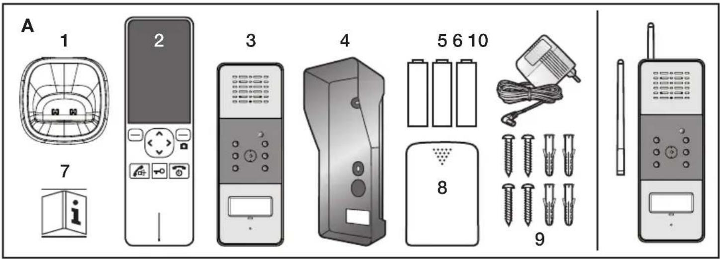
Parts included (Fig. A)
When you unpack your product, make sure that all the parts shown in Fig. A are included. If any parts are missing or damaged, please contact your retailer immediately.
- Indoor unit (charging cradle)
- Indoor unit (handset)
- Outdoor unit
- Waterproof housing
- 3 x AAA Ni-MH rechargeable batteries
- Power pack (7.5 V/300 mA)
-
Operating instructions
-
Battery compartment cover, indoor unit
- Screws
- Aerial (optional)
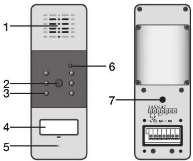
Diagram of outdoor unit (Fig. B)
1 Speaker
2 Camera
3 LED light
4 Call button (with nameplate)
5 Microphone
6 Light sensor
7 Register button
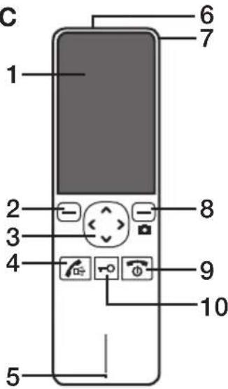
Diagram of indoor unit (Fig. C)
1 Display
2 Left-hand softkey
3 Navigation button
4 Answer call button
5 Microphone
6 Aerial
7 Aerial locking switch
8 Right-hand softkey (manual snapshot)
9 On/off/end call button
10 Open door button
11 Speaker
12 Battery compartment cover
13 Charger contacts
Charging cradle, indoor unit
14 Connection jack
15 Charger contacts
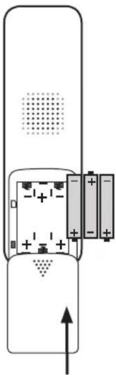
Inserting the batteries into the indoor unit (Fig. D)
- 3 x Ni-MH rechargeable batteries (size AAA, 1.2 V, 800 mAh) are included with the device. Insert the batteries before using the device, making sure that they are the right way round (+,-).
- Close the battery compartment by sliding the cover upwards until it clicks into place.
Note:
Inserting the batteries the wrong way round may damage the handset. Rechargeable batteries that no longer reach their full capacity when charged must be replaced.
When replacing the batteries, always use high-quality Ni-MH rechargeable batteries. Never use other types of rechargeable battery or conventional alkaline batteries.
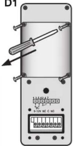
Inserting the batteries into the outdoor unit (Fig. D1)
- Insert two C-size batteries (not included) into the battery compartment.
- Fix the cover into place with the four screws provided.
Charging the handset
NB: FULLY CHARGE HANDSET BEFORE INITIAL USE (approx. 15 hours).
To do so, place the handset in the charging cradle.
Installing the indoor unit
Insert the power pack connector into the charging cradle connection jack and plug the power pack into into a power outlet (alternating current) (Fig. E).
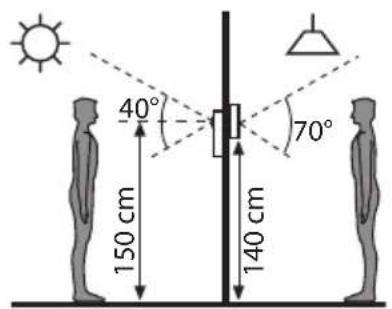
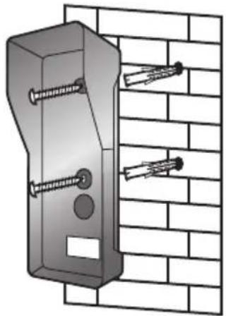
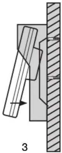
Installing the outdoor unit (Fig. F)
- Choose an appropriate location for the outdoor unit, taking into account the average eye level of visitors (Fig. F1).
- Align the waterproof housing and screws with the holes in the wall (Fig. F2).
- Hang the outdoor unit inside the waterproof housing (Fig. F3).
- Fasten the housing into place by inserting a screw at the bottom to complete the installation. (Fig. F4).
- If required, screw on the (optional) aerial provided to increase the range (Fig. F5).
Note:
Do not install the device by electrical appliances, such as TVs, computers or other cordless phones, or on a metal base.
Install the device in a RAISED and EASILY ACCESSIBLE location, at a suitable distance from microwaves and WiFi devices. Release the lock of the (optional) aerial to improve the signal reception.
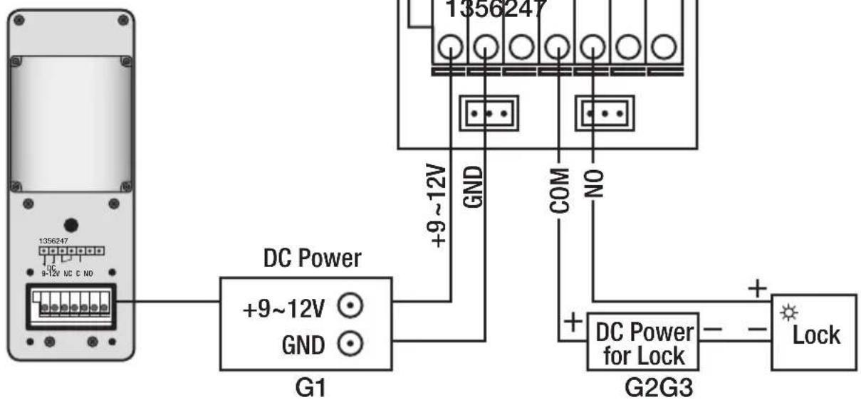
Circuit diagram (Fig. G)
G1 DC power
G2 DC power for electric door opener
G3 Electric door opener
Note:
The outdoor unit can either be operated by batteries or the power supply, but not both at the same time (Fig. G). Please switch to the power supply for specific functions such as monitoring or backlighting of the call button and door opener. The power pack requires a minimum output of 9-12 V/500 mAh, plus the power requirement of the door opener. We recommend installing a power pack.
Operations
Switching on/off
Press and hold to switch the indoor unit on. Press and hold to switch the indoor unit off.
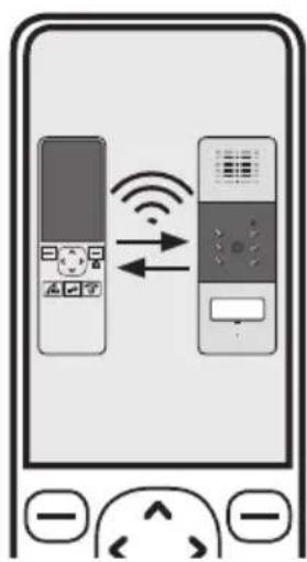
Registration
Press the call button (Fig. B4) on the outdoor unit, then press and hold the register button (Fig. B7) on the back of the outdoor unit until the six camera LEDs start flashing. Press—on the indoor unit under
Menu, then select the register menu. One beep indicates that the outdoor unit was successfully registered with the indoor unit.
Two beeps indicate that the registration was unsuccessful. Turn off the indoor unit, remove the batteries from the outdoor unit then press and hold the register button (Fig. B4). Switch the indoor unit back on, reinsert the batteries into the outdoor unit and try registering the unit again.
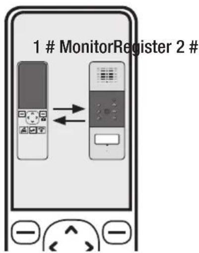
Registration
Once you have registered the outdoor unit, the message shown in Fig. H will appear on the display.
Operations
Calling the indoor unit
In standby mode, press the call button on the outdoor unit. The indoor unit will ring and an image of the visitor will appear on the display.
- If you do not wish to answer the indoor unit, press ☐ to cancel the ring tone and image.
-
If you press on the indoor unit, it will stop ringing and the call will start.
-
Press to end the call.
Note:
The call may last up to two minutes; after this time, the line will be automatically disconnected.
You can use the monitor function for up to five minutes; after this time, the indoor unit will automatically quit monitoring mode.
Opening the door
Press ☐ on the indoor unit during a call to open the door (only in power pack mode and with optional door opener installed).
Light sensor
If a visitor presses the call button on the outdoor unit after dark, the LED lighting will be switched on.
Menu description
Date and time
-
Press ☐ under Menu to display the main menu items.
-
Press ☐ to select, then press under Select.
-
To set the time, press or to select the hour or minute, then press or to adjust the values.
-
To set the date, press ☑ or to select the year, month or day, then press ☑ or to adjust the values.
-
Press 📋 under Back to return to the menu.
Note:
The time is entered in 24-hour format and the date in YY-MM-DD format.
The date and time must be set in advance for the data displayed on the monitoring images to be correct.
The time and date need to be reset whenever the batteries are replaced.
Set the date and time in the following order: Hour, minute, month, day.
Volume
You can use this function to adjust the talk volume to one of nine levels.
-
Press ☐ under Menu to display the main menu items.
-
Press ☑ to select, the ☑ press under—Select to confirm.
-
Press ☑ to select the required volume level. Each time you press for the handset will ring at the selected volume.
-
Press ☐ under Back to save your settings and return to the previous menu.
Note:
You can also adjust the volume in standby mode by pressing 📄.
Keypad tones
Every time you press a key, the handset acknowledges it with a keypad tone, which can be deactivated if desired. If you press the wrong button, a warning tone will sound.
- Press ☐ under Menu to display the main menu items.
- Press ☐ to select, then press under Select to confirm.
- Press ☑ to select On or Off to enable or disable this function.
- Press ☐ under Select to save your settings and return to the previous menu.
Activating the snapshot function
You can use the snapshot function to take up to 50 snapshots of your visitors, whether you are at home or not. You can set up the auto snapshot function on your handset as follows:
- Press under Menu to display the main menu items.
- Press 📂 to select, then press under Select to confirm.
- Press ☑ to select On or Off to enable or disable this function.
- Press ☐ under Select to save your settings and return to the previous menu.
If the auto snapshot function is on, the camera will automatically take a photo of anyone who presses the call button on the outdoor unit. You can then view the photos on your handset.
Note:
Press the snapshot button during a call to take a photo of a visitor and save it on your handset.
Press the snapshot button (Fig. C8) in monitoring mode to take a photo of the surrounding view and save it on your handset.
You can save around 50 photos on the handset. When the photo memory is full, each time you take a new photo an old one will be automatically deleted. It is not possible to export your saved photos.
Snapshot slide show
In this menu you can save new photos or delete saved photos.
- Press ☐ under Menu to display the main menu items.
- Press ☑ to select, then press under Select to confirm.
- Press or to browse your photos.
- If you wish to delete the photo displayed, then press □under Delete. Delete will appear on the display; press □under Yes to confirm. You will hear a beep tone, then the next photo will appear on the display.
- Press Under Back to return to the previous menu.
Factory settings
You can use this function to reset the handset to its factory settings.
- Press ☐ under Menu to display the main menu items.
- Press ▲ to select, then press under Select to confirm.
- Press ☑ to select On or Off to enable or disable this function.
- Press 📋 under Select to save your settings and return to the previous menu.
Result: After a reset, the handset will return to standby mode.
Note:
If you use this function, all handset settings will be reset to their factory settings.
Clearing a registration
- In standby mode, press and hold 📄 and 📄 under Menu for around five seconds. The following message will appear on the display: Registration Cleared!
- The message will disappear after five seconds.
Setting the door unlock time
- In standby mode, press and hold 📄 and 📋 for around five seconds. The following message will
appear on the display: Unlock Time
- Press or to select the outdoor unit.
- Press ☑ to select an unlock time (between 1 and 25), then press the right-hand softkey under SAVE to confirm. OK will appear on the display.
- The message will disappear after five seconds.
Note: If you are using a door opener with a memory function, the unlock time should be set to the shortest interval. e.g. #1 1S.
Battery and rechargeable battery information
Used batteries must not be disposed of as unsorted household waste. Used batteries must be recycled and may be returned free-of-charge to the place of sale. Batteries contain substances which are harmful to the environment and to human health and must therefore be disposed of correctly.
Recycling instructions
This device must not be disposed of as unsorted household waste. Used devices must be disposed of correctly. Contact your local town council for more information.
Troubleshooting
Problem Possible cause
The display is black • Batteries charged?
- Batteries the right way round?
The display is working but the images are not being transferred
- Check distance
The image is too light/dark • Adjust brightness (see instructions)
Ring tone is too loud/quiet • Adjust volume
Technical data CVF 86012
Indoor unit Specifications
Receiving frequency range 2.400 GHz - 2.4835 GHz
Colour display 2.4" / 61 mm
Data rate 2.0 Mbps
Receiving sensitivity -90 dBm
Demodulation GFSK
Resolution 320 240 (RGB)
Transmitting power 19 dBm (TYP)
Power requirement 3 x Ni-MH, 1.2 V, 800 mAh
Power consumption
max. 450 mA
Operating temperature
-10°C to +40 °C
Humidity
0 - 85% relative humidity
Weight
110 g
Dimensions
Handset: approx. W 50 x H 165 x D 27 mm
Charging cradle: approx. W 77 x H 79 x D 42 mm
Outdoor unit
Transmitting frequency range
Specifications
2.400 GHz - 2.4835 GHz
Data rate 2.0 Mbps
Transmitting power 19 dBm (TYP)
Modulation
GFSK
Transmission range
Outdoors: max. 200 m, indoors: max. 50 m
Sensor type
1/4" colour CMOS image sensor
Effective pixel count:
H:320 V:240
Image processing
Motion JPEG
Image resolution / frame rate
H: 320 V: 240/25 fps
White balance
automatic
Lens
4.9 mm F2.8
Viewing angle (diagonal)
50
Illuminance
Min. 1 LUX (without LED lighting)
Number of LEDs
6
Power requirement +9 - 12 V DC/2 LR14 (C) 1.5 V batteries
Power consumption
max. 500 mA (with batteries), max. 400 mA (with +12 V DC)
Operating temperature
-30 °C to +40 °C
Humidity
0 - 85 % relative humidity
Weight
166 g
Dimensions
approx. W 68 x H 185 x D 50 mm
Power pack
Power supply
Specifications
Power output
230 V AC, 50 Hz, max. 0.2 A
7.5 V DC, 0.3 A
The device has been approved for distribution within the European Union.
GEV GmbH GmbH hereby declares that this CVF 86012 radio video doorphone system complies with the basic requirements and other relevant provisions of Directive 1999/5/EC.
The full text of the declaration of conformity can be found at: http://www.gev.de
GEV
GEV GmbH
Heidehofweg 16
25499 Tangstedt
Germany
www.gev.de
service@gev.de
Hotline: +49 (0)180/59 58 555
CE
International calls may vary.