
Quantum Mini - Pump Baxi - Free user manual and instructions
Find the device manual for free Quantum Mini Baxi in PDF.
| Product type | Wet rotor circulator for heating installation |
| Dimensions (L x W x H) | Approx. 180 x 100 x 130 mm |
| Weight | Approx. 1.5 kg |
| Power supply | 1~230 V ±10%, 50 Hz |
| Power consumption | Variable depending on setting, max. 0.5 A |
| Protection class | IP (see rating plate) |
| Temperature class | TF 95 |
| Max. operating pressure | 6 bar (600 kPa) |
| Fluid temperature | -10°C to +95°C |
| Max. ambient temperature | +40°C |
| Connection diameters | DN 15 (Rp 1/2"), DN 25 (Rp 1"), DN 30 (Rp 1 1/4") |
| Energy efficiency index (EEI) | See rating plate (≤0.20 for most efficient) |
| Regulation modes | Variable differential pressure (Δp-v) and constant speed (I, II, III) |
| Main functions | Electronic switching, automatic regulation, frost protection |
| Routine maintenance | Automatic venting; clean the body with a damp cloth |
| Safety | Emergency stop via circuit breaker, drip-proof protection, child safety (age >8 years) |
| Spare parts | Gaskets, connection cable, sealing rings (original) |
| Repairability | Do not open the motor; intervention by a qualified professional |
| General information | Brand Baxi, model Quantum Mini, pump range |
Frequently Asked Questions - Quantum Mini Baxi
User questions about Quantum Mini Baxi
0 question about this device. Answer the ones you know or ask your own.
Ask a new question about this device
Download the instructions for your Pump in PDF format for free! Find your manual Quantum Mini - Baxi and take your electronic device back in hand. On this page are published all the documents necessary for the use of your device. Quantum Mini by Baxi.
USER MANUAL Quantum Mini Baxi
natural_image
Technical line drawing of a mechanical device with no visible text or symbolsQuantum MINI
es Instrucciones de instalación y funcionamiento pt Manual de Instalação e funcionamento en Installation and operating instructions fr Notice de montage et de mise en service
Fig.1:
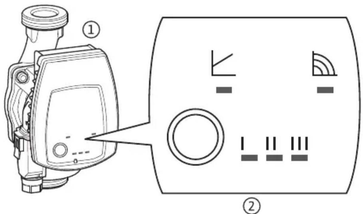
Fig. 2a: Fig. 2b:
H
H
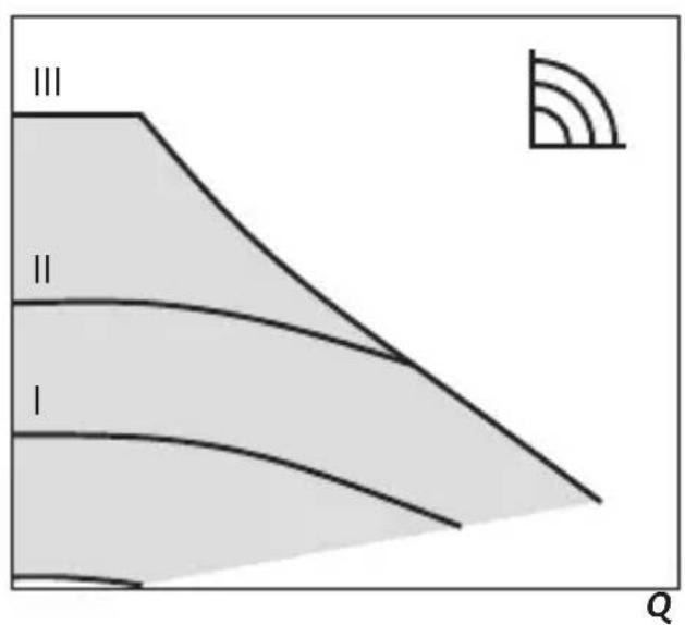
Fig. 3:
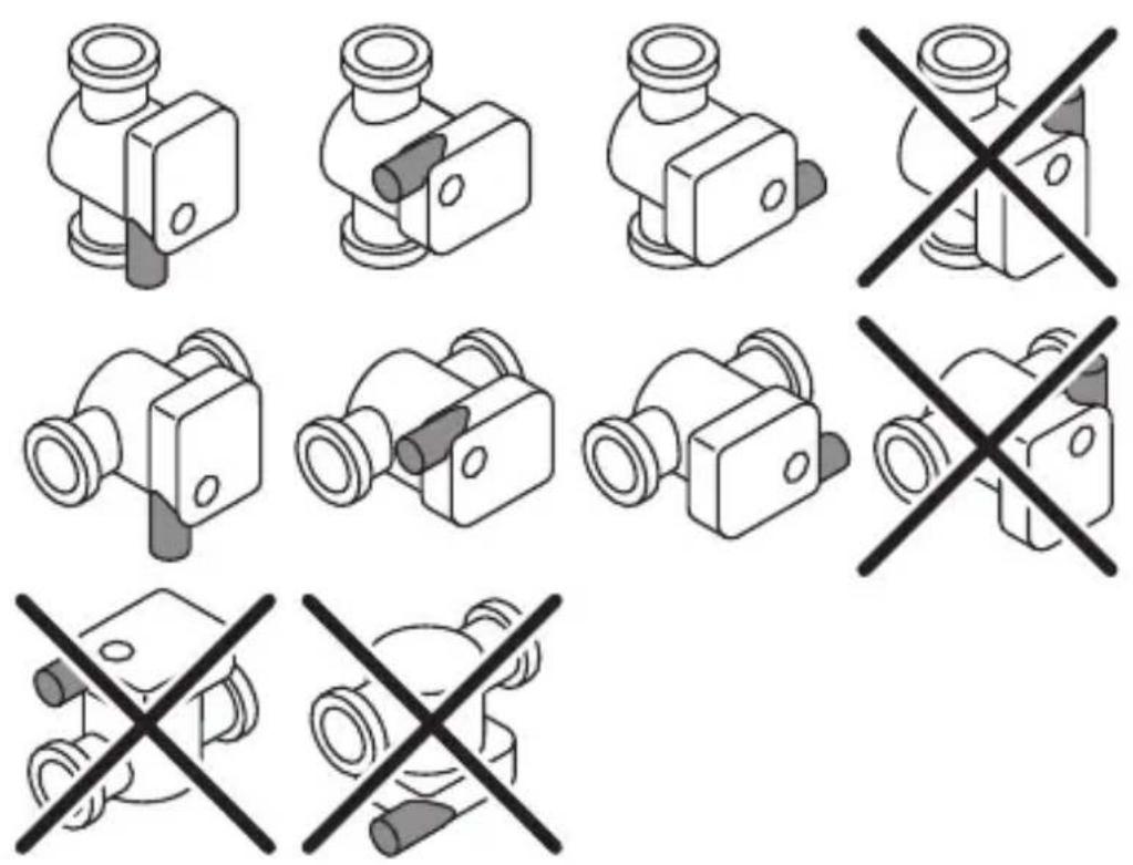
Fig. 4a: Fig. 4b:
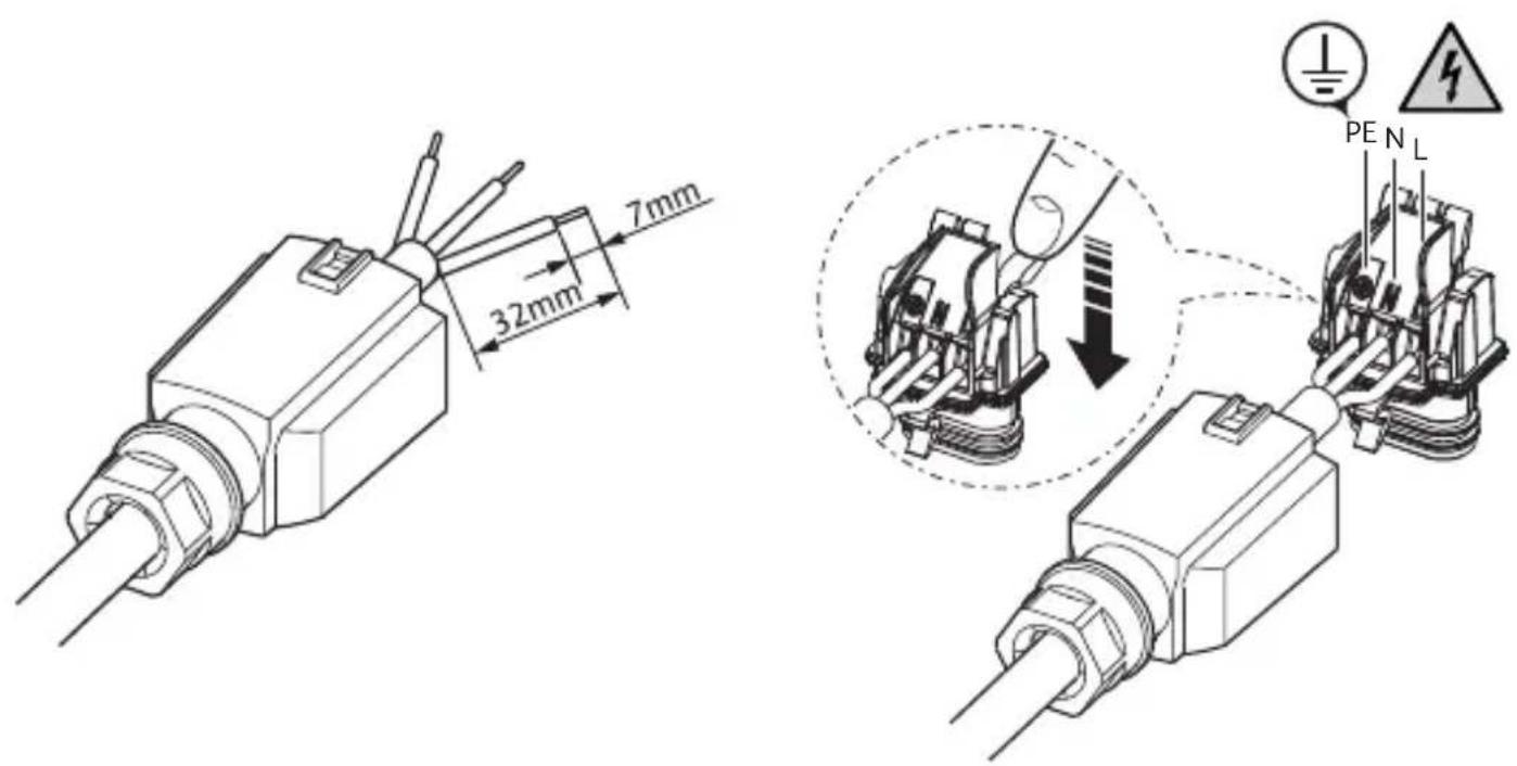
Fig. 4c: Fig. 4d:
natural_image
Technical line drawing of a mechanical connector assembly (no text or symbols)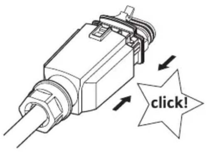
Fig. 4e: Fig.5:
natural_image
Technical line drawing of a mechanical component with a rotating shaft and housing (no text or symbols)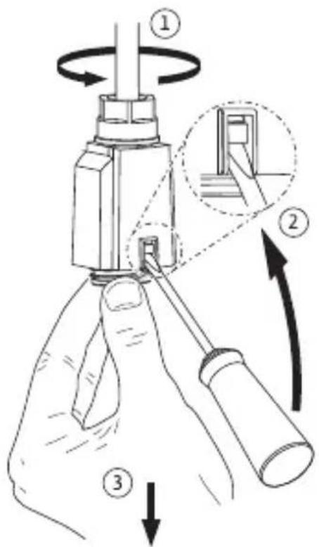
en Installation and operating instructions 32
natural_image
Pure electrical circuit symbols without any text or labelsPresionar
natural_image
Pure electrical circuit symbols without any text or labelsnatural_image
Pure electrical circuit symbols without any text or labels1.1 About these instructions
- Read these instructions through completely before installation.
Not following these instructions can result in injury to persons or damage to the pump. - Once installation work is complete, pass the instructions on to the end user.
- Keep the instructions near the pump. They can be used for reference if problems occur later.
- No liability will be accepted for damages resulting from failure to follow these instructions.
1.2 EC-Declaration of conformity
This product complies with European directives in terms of design and performance characteristics, as well as to supplementary national requirements. Conformity has been certified with the CE mark. Further information on the declaration of conformity for this product can be found online at www.baxi.es or requested from the relevant BAXI branch.
1.3 Safety information
Important safety information is indicated as follows:

DANGER: Indicates a risk of fatal injury due to electrical current.

WARNING: Indicates a possible danger to life or risk of injury.
CAUTION: Indicates a possibility of property damage.
NOTICE: Highlights tips and information.
1.4 Qualifications
- The pump may only be installed by qualified personnel. The electrical connection may only be established by a qualified electrician.
- This device can be used by children from 8 years old as well as by persons with limited physical, sensory, or mental capabilities or lack of experience and knowledge provided they are supervised or have been instructed in the safe use of the device and understand the dangers that may arise. Children must not be not allowed to play with the device. Cleaning and maintenance by the user must not be carried out by children without supervision.
1.5 Regulations
- The current versions of the following regulations must be observed during installation:
- Accident prevention regulations
• VDE 0700/Part 1 (EN 60335-1)
- Other local regulations (e.g. IEC, VDE)
1.6 Conversion and spare parts
Unauthorised modification and manufacture of spare parts will impair the safety of the product/personnel and void the manufacturer's declarations regarding safety.
- The pump must not be technically modified or converted.
- Opening the pump motor by removing the plastic lid is not permitted.
- Only use original spare parts.
1.7 Transport/storage
Unpack and check the pump and all accessories upon receipt. Report any damage sustained in transit immediately. Only ship the pump in its original packaging.
The pump is to be protected from moisture, frost, and mechanical damage and must not be exposed to temperatures outside the range of -10 ^ to +50 ^ .
1.8 Electrical current
There is a danger of electric shock when working with electrical current. For this reason:
- Switch off the power before beginning work on the pump, confirm that the system is voltage-free, and ensure that it cannot be switched on again accidentally.
- Do not kink or pinch the power cable or allow it to come into contact with sources of heat.
- Never open the control module and never remove operating elements.
- The pump is protected against drips in accordance with IP protection class (see rating plate). Protect the pump from water spray. Do not immerse in water or other fluids.
- The connection must be secured by means of a residual-current device (RCD).
2 Technical data
2.1 Data
| Quantum MINI | |
| Connection voltage | 1~230 V ±10%, 50 Hz |
| Temperature class TF 95 | |
| Protection class IP See rating plate | |
| Energy Efficiency Index EEI * See rating plate | |
| Nominal connection diameter(Screwed connection) | DN 15 (Rp 1/2), DN 25 (Rp 1),DN 30 (Rp 11/4) |
| Water temperatures at a max.ambient temperature of +40 °C | -10 °C to +95 °C |
| Max. ambient temperature -10 °C to | +40 °C |
| Max. operating pressure 6 bar (600 kPa) | |
| Minimum inlet pressure at +95 °C 0.3 bar (30 kPa) | |
* Reference value for the most efficient circulators: EEI ≤ 0.20
2.2 Scope of delivery
- Pump
- Seal rings
- Plug
• Installation and operating instructions
3 Description and function
3.1 Intended use
The circulators in this series are designed for warm water heating systems and similar systems with constantly changing flows.
The approved fluids are heating water in accordance with VDI 2035, and water/glycol mixture at a mixing ratio of 1:1.
If glycol is added, the delivery data of the pump must be corrected according to the higher viscosity depending on the mixing ratio.
Intended use includes the observation of these instructions as well as of specifications and labelling on the pump.
Any other use is regarded as improper use.
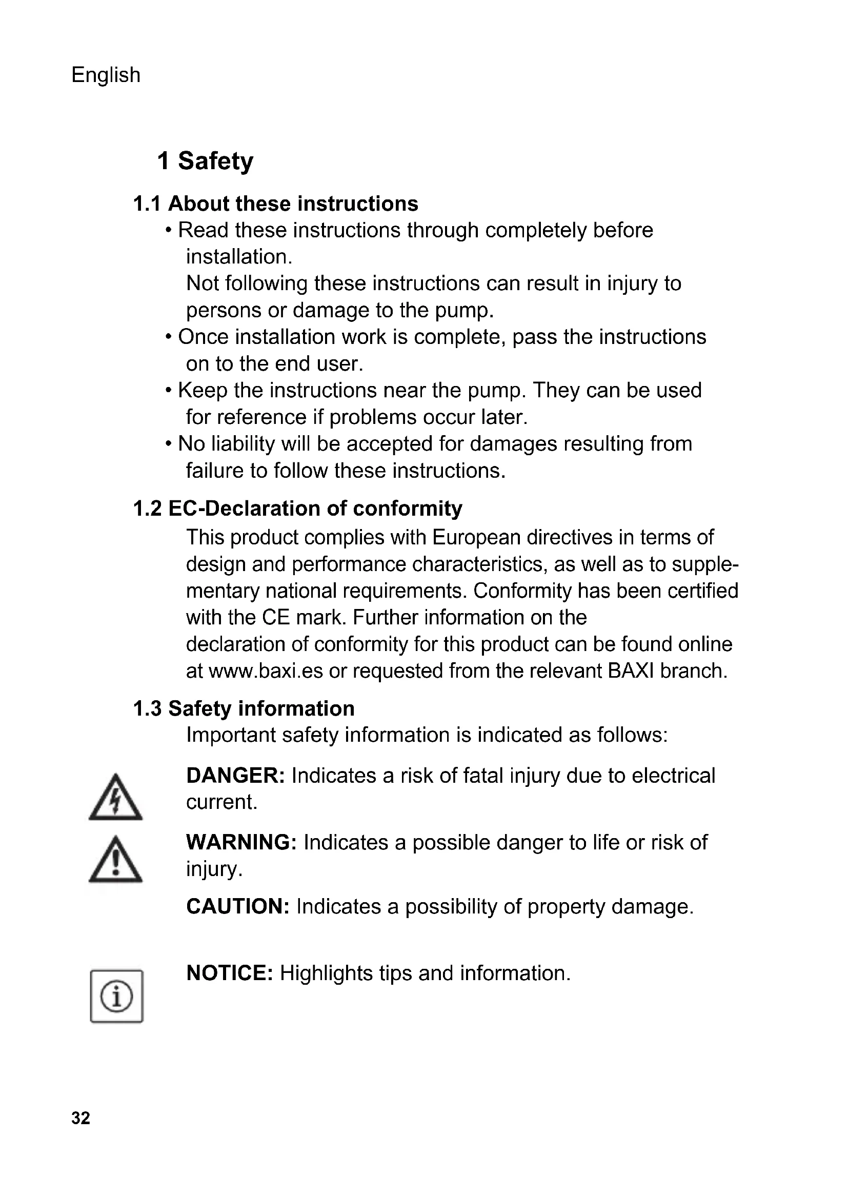
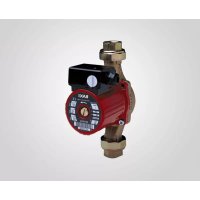
3.2 Product description
The pump (Fig. 1/1) consists of a hydraulic system, a glandless motor with a permanent magnet rotor, and an electronic control module with integrated frequency converter.
The control module contains an operating button and LEDs (Fig. 1/2) for setting and displaying all parameters.
3.3 Functions
Operating button
Control modes

Variable differential pressure ( p-v ):
If the volume flow in the pipe network decreases, the pump reduces the delivery head by half (Fig. 2a).
Optionally with three pre-set characteristic curves (I, II, III).
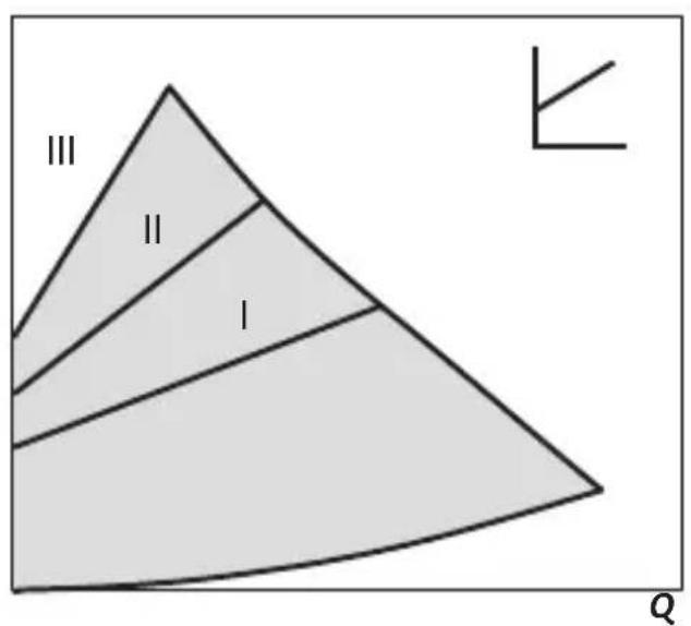
Constant speed (I, II, III):
The pump runs at three specified constant-speed settings (Fig. 2b).
4 Installation and electrical connection
4.1 Installation
DANGER: Before starting work, make sure that the pump is disconnected from the power supply.
Installation site
- Provide a weatherproof, frost-free, dust-free, and well-ventilated room for the installation.
Choose an easily accessible installation site.
- Prepare the installation site so that the pump can be installed without being subjected to mechanical stresses. If necessary, support or secure piping on both sides of the pump.

NOTICE: Provide shut-off devices upstream and downstream of the pump to facilitate potential future pump replacement. Perform the installation in a way that prevents leaking water from dripping onto the control module. To do this, align the upper gate valve laterally if necessary.
- Complete all welding and soldering work near the pump prior to the installation of the pump.
CAUTION: Dirt can cause the pump to fail. Flush the pipe system before installation.
- Choose the correct installation position, with the pump motor in a horizontal position, from only the positions shown in (Fig. 3). Direction arrows on the pump housing indicate the direction of flow.
- If heat insulation work is necessary, only the pump housing may be insulated. The pump motor, module, and condensate drainage openings must remain uncovered.
Turning the motor head
If the installation position of the module is changed, the motor housing must be turned as follows:
- If necessary, remove the thermal insulation shell.
- Loosen the interior hexagonal head screws.
- Turn the motor housing, including the control module.

NOTICE: In general, turn the motor head before the system is filled. When turning the motor head in a system that has already been filled, do not pull the motor head out of the pump housing. Turn the motor head with a small amount of pressure on the motor unit so that no water can come out of the pump.
CAUTION: Do not damage the housing seal. Replace damaged gaskets.
- Turn the motor head in such a way that the plug corresponds to the permitted installation position (Fig. 3).
CAUTION: If the position is wrong, water can penetrate and destroy the pump.
- Turn in the interior hexagonal head screws.
- If applicable, re-mount the thermal insulation shell.
4.2 Electrical connection
DANGER: Work on the electrical connection must be performed only by a qualified electrician and in accordance with national and local regulations. Before making the connection, ensure that the connecting cable is not live.
- The mains voltage and current type must correspond to the rating plate specifications.
-
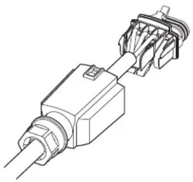
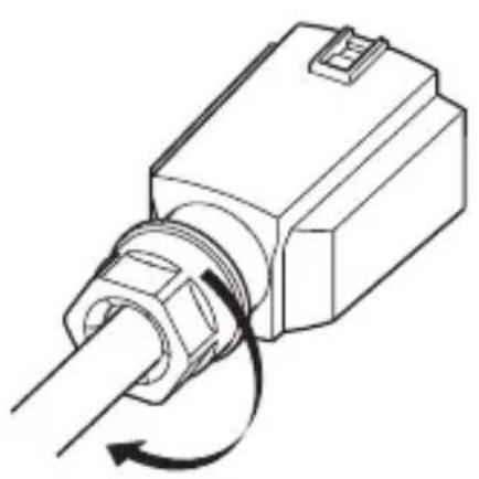
Connect the plug (Fig. 4a to 4e).
-
Mains connection: L, N, PE.
- Max. back-up fuse: 10 A, slow-blow.
- Earth the pump in accordance with instructions.
Dismantle the plug in accordance with Fig. 5. A screwdriver is required to do this.
- The electrical connection is to be established via a fixed connecting cable equipped with a connector device or an all-pole switch with a contact opening width of at least 3 mm.
- To ensure drip protection and strain relief at the PG screwed connection, a connecting cable with an adequate outer diameter is required (e.g. H05VV-F3G1.5).
- For pumps in systems with water temperatures above 90 °C, install a suitably heat-resistant connecting cable.
- The connecting cable is to be laid in such a way that it can under no circumstances come into contact with the pipe and/or the pump and motor housing.
- The switching of the pump using triacs / solid-state relays must be tested on a case-by-case basis.
CAUTION: Voltage pulsing during phase angle control or external control can cause damage to electronic components.
- Only operate the pump with sinusoidal AC voltage as stated on the rating plate.
- The switching of the pump using triacs / solid-state relays must be tested on a case-by-case basis.
5 Commissioning/operation

WARNING: Depending on the pump or the system operating conditions (fluid temperature), the entire pump can become very hot. There is a risk of burns upon coming into contact with the pump! Commissioning by qualified personnel only!
5.1 Venting
- Fill and vent the system appropriately.
- The pump rotor space vents automatically after a short time in operation. This may cause noises. If necessary, switch off and on again repeatedly to speed up the venting process. The pump will not be harmed by dry running for short periods.
5.2 Setting the control mode
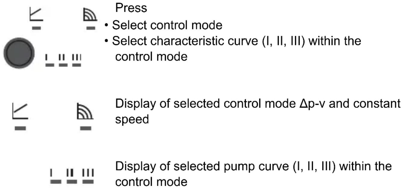
Selecting the control mode
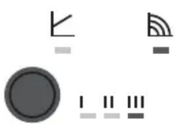
The control modes and corresponding characteristic curves are shown on the LED display in clockwise succession.
natural_image
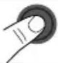
Pure electrical circuit symbols without any text or labelsPress the operating button briefly (approx. 1 second).
The LEDs display the set control mode and characteristic curve.
The following demonstrates the display of the possible settings (example: constant speed / characteristic curve III):
| LED display Control mode Characteristic curve | ||
| 1. Constant speed | II | |
 | LED display Control mode Characteristic curve | |
| 2. Constant speed | I | |
| 3. Variable differential | pressure Δp-v | III |
| 4. Variable differential | pressure Δp-v | II |
| 5. Variable differential | pressure Δp-v | I |
| 6. Constant speed | III | |
After pressing the button 6 times, the selection will have returned to the basic setting (constant speed / characteristic curve III).

NOTICE: All settings and displays are retained if the mains supply is interrupted.
6 Maintenance/faults
DANGER: Before starting any maintenance and repair work, disconnect the pump from the power supply and make sure it cannot be switched back on by unauthorised persons.
- Damage to the connection cable must always be repaired by a qualified electrician.
- Faults must only be remedied by qualified personnel!

WARNING: Risk of burns when touching the pump!
Depending on the pump or the system operating conditions (fluid temperature), the entire pump can become very hot.
When removing the motor head or pump, hot fluid may be expelled under high pressure.
- Allow the pump to cool down first.
- Close the stop valves before removing the pump. There is always a strong magnetic field inside the motor. The permanent magnet rotor installed in the pump can pose mortal danger to people with medical implants (e.g. pacemakers) during dismantling.
- Never open the motor and never remove the rotor.
| Fault Cause Remedy | ||
| Pump is not running although the power supply is switched on | Electrical fuse defective | Check fuses |
| No voltage supply to the pump | Resolve the interruption to the power supply | |
| Pump is noisy Cavitation due to insufficient suction pressure | Increase the system supply pressure within the permissible range | |
| Check the delivery head setting and set it to a lower height if necessary | ||
| Building does not warm up | Thermal output of the heating surfaces is too low | Increase setpoint |
7 Disposal
Information on the collection of used electrical and electronic products
Proper disposal and recycling of this product prevents damage to the environment and risk to personal health.
NOTICE:
Disposal in domestic waste is forbidden!
Electrical and electronic products with this marker must not be disposed of in domestic waste.
- Use public or private disposal organisations when disposing of the product or parts of the product.
- For more information about proper disposal, please contact your local council or waste disposal office or the supplier from which you obtained the product.
Subject to technical modifications without prior notice.
1 Sécurité
1.7 Transport/stockage
natural_image
Pure electrical circuit symbols without any text or labels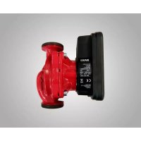
- Quantum MINI
- Presionar
- About these instructions
- EC-Declaration of conformity
- Safety information
- Qualifications
- Regulations
- Conversion and spare parts
- Transport/storage
- Electrical current
- Technical data
- Data
- Scope of delivery
- Description and function
- Intended use
- Product description
- Functions
- Operating button
- Control modes
- Variable differential pressure ( p-v ):
- Constant speed (I, II, III):
- Installation and electrical connection
- Installation
- DANGER: Before starting work, make sure that the pump is disconnected from the power supply.
- Installation site
- CAUTION: Dirt can cause the pump to fail. Flush the pipe system before installation.
- Turning the motor head
- CAUTION: Do not damage the housing seal. Replace damaged gaskets.
- Electrical connection
- Commissioning/operation
- Venting
- Setting the control mode
- Selecting the control mode
- Maintenance/faults
- Disposal
- Information on the collection of used electrical and electronic products
- NOTICE:
- Disposal in domestic waste is forbidden!
- Sécurité
- Transport/stockage
Brand : Baxi
Model : Quantum Mini
Category : Pump