
SB50 XA - Pump Baxi - Free user manual and instructions
Find the device manual for free SB50 XA Baxi in PDF.
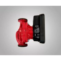
| Product type | Domestic hot water circulator (wet rotor pump) |
| Brand | Baxi |
| Model | SB50 XA (SB-4X range) |
| Power supply | Single-phase 230 V / 50 Hz, 5 W |
| Protection rating | IP 42 |
| Connection | Threaded R 1/2 (Rp 1/2) |
| Installation length | 84 mm (type A/C: 138 mm) |
| Max. operating pressure | 10 bar |
| Fluid temperature range | +2 °C to +65 °C (temporary +70 °C for 2 h) |
| Max. ambient temperature | +40 °C |
| Max. water hardness (DHW loop) | 36 °fH |
| Integrated functions | Non-return valve on discharge side, shut-off valve on suction side |
| Application | Potable water only |
| Installation | Installation by qualified personnel, electrical connection by an electrician |
| Routine maintenance | Clean the exterior with a slightly damp cloth (without detergent) |
| Motor head replacement | Possible without draining (integrated shut-off valves) |
| Safety | Disconnect power before any intervention |
| Spare parts | Motor head, gaskets, connector, thermal insulation shell |
| Warranty / Compliance | CE, European directives |
Frequently Asked Questions - SB50 XA Baxi
User questions about SB50 XA Baxi
0 question about this device. Answer the ones you know or ask your own.
Ask a new question about this device
Download the instructions for your Pump in PDF format for free! Find your manual SB50 XA - Baxi and take your electronic device back in hand. On this page are published all the documents necessary for the use of your device. SB50 XA by Baxi.
USER MANUAL SB50 XA Baxi
Installation, Assembly and Operation Instructions for the INSTALLER and USER
6%□□; 6%□□;
natural_image
Technical line drawing of a mechanical device with threaded ports and a base (no text or symbols)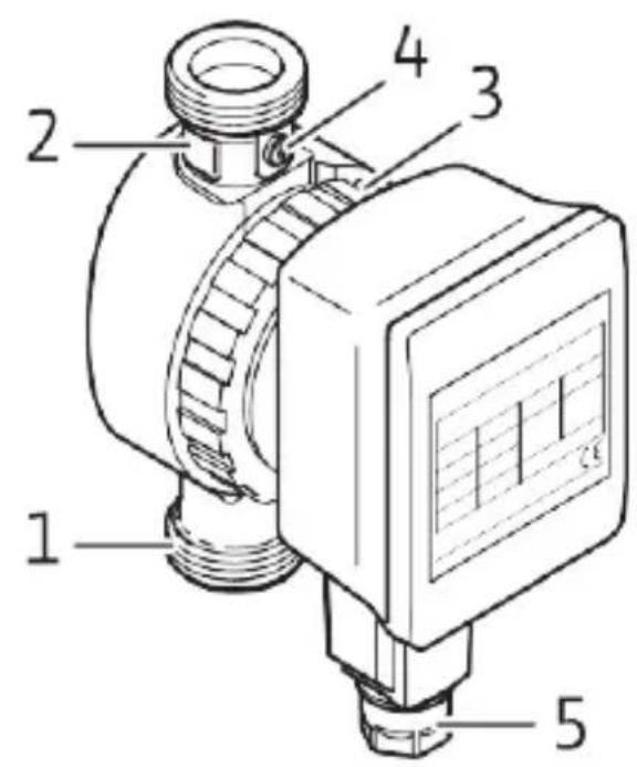
Fig. 3: Fig. 4:
natural_image
Technical illustration of two mechanical components with directional arrows indicating motion (no text or symbols)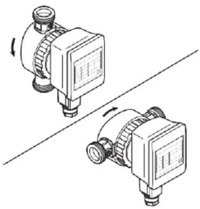
natural_image
Technical line drawing of two mechanical pressure regulator components with rotating arrows (no text or symbols)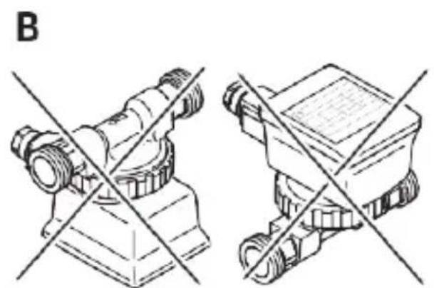
natural_image
Technical line drawing of two mechanical components with cross-sectional lines, no text or symbols presentFig. 5: Fig. 6:
natural_image
Line drawing of a wrench tool interacting with a bolt and nut (no text or symbols)Fig. 7a:
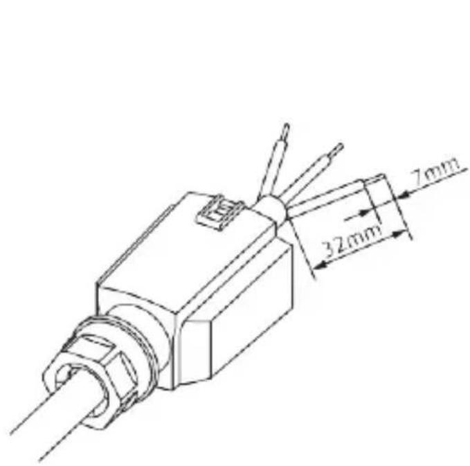
Fig. 7b:
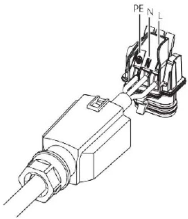
Fig. 7c:
natural_image
Technical line drawing of a mechanical connector assembly (no text or symbols)Fig. 7d:
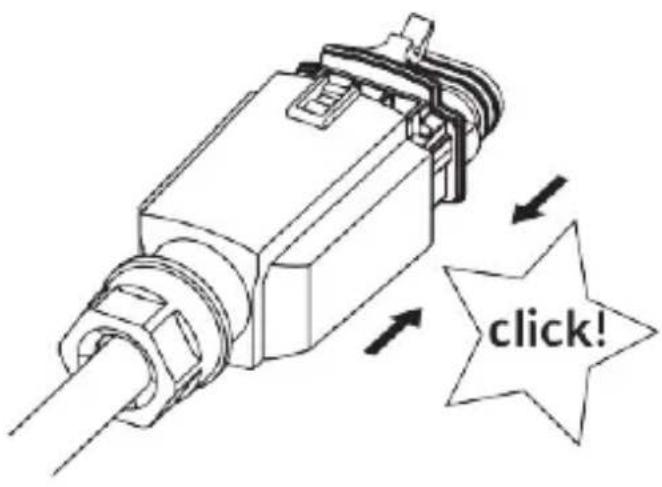
Fig. 7e: Fig. 8:
natural_image
Technical line drawing of a mechanical component with a rotating shaft and housing (no text or symbols)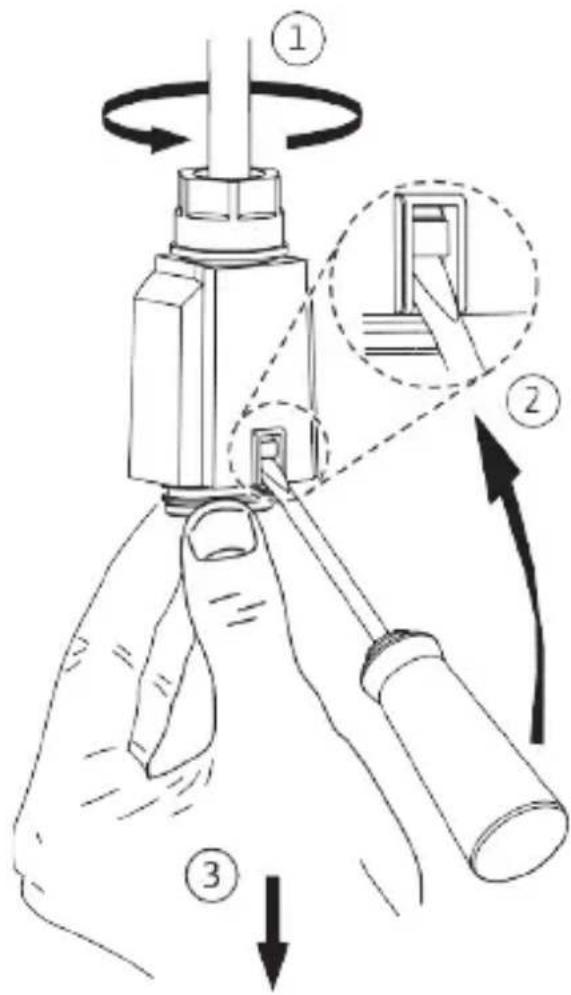
1 Safety
1.1 About these instructions
Read through these instructions completely before installation. Non-observance of these instructions can result in injury to persons and damage to the pump/unit.
Once installation work is complete, pass the instructions on to the end user.
Keep the instructions near the pump. They can be used as a reference if problems occur later.
We accept no liability for damages resulting from failure to follow these instructions.
1.2 CE Declaration of Conformity
The design and operation of this product conform to the applicable European directives and supplementary national requirements. Conformity has been demonstrated.
The Declaration of Conformity can be viewed at www.baxi.es or alternatively can be requested from your local BAXI sales office.
1.3 Safety information
Important safety information is indicated as follows:

DANGER: Indicates a danger to life due to electrical current.
WARNING: Indicates a possible danger to life or injury.
CAUTION: Indicates possible risks to the pump or other items.
NOTE: Highlights tips and information.
1.4 Qualification
The pump may only be installed by qualified personnel. This product may not be commissioned or operated by persons with insufficient accountability (including children) or who do not possess the relevant specialist knowledge. Exceptions are only permitted on appropriate instruction from safety-responsible persons. The electrical connection may only be established by a qualified electrician.
1.5 Regulations
The current versions of the following regulations must be observed when installing the equipment:
• Accident prevention regulations
- Worksheets
- Other local regulations
1.6 Conversion, spare parts
The pump must not be technically modified or converted. It is not permitted to open the pump motor by removing the plastic lid. Only use original spare parts.
1.7 Transport
Unpack and check the pump and all accessories upon receipt. Report any damage sustained in transit immediately.
Dispatch the pump in the original packing only.
1.8 Electrical current
There is a danger of an electric shock when working with electrical current. Therefore:
- Switch off the power before beginning work on the pump and make sure that it cannot be switched on again accidentally.
- Do not kink or nip the power cable or allow it to come into contact with heat sources.
- The pump is protected against drips in accordance with protection class IP 42. Protect the pump against water spray. Do not immerse in water or other fluids
2 Technical Data
2.1 Type key
SB-4X Series:
Standard secondary hot water circulation pump, glandless pump with check valves
2.2 Connections (Fig. 1)
SB-4X
Screwed connection: 15 (Rp 12 ") and check valves
2.3 Data
| SB-4X | |
| Mains voltage | 1 ~ 230 V / 50 Hz |
| Protection class | IP 42 |
| Nominal diameter of connecting pipes | R 1⁄2 |
| Installation length | 84 mm (Type A/C: 138 mm) |
| Max. permissible operating pressure | 10 bar |
| Permitted fluid temperature range | +2°C to +65 °C in short-term operation to 2 hours 70 °C |
| Max. ambient temperature +40 °C | |
| Max. permitted hardness in secondary hot water circulation systems | 36° fH |
See name plate or catalogue for further information.
2.4 Scope of delivery
- Pump
• Thermal insulation shell - Sealing rings
- Connector
• Installation and operating instructions
3 Principle of operation
3.1 Application
This circulator is suitable for drinking water only.
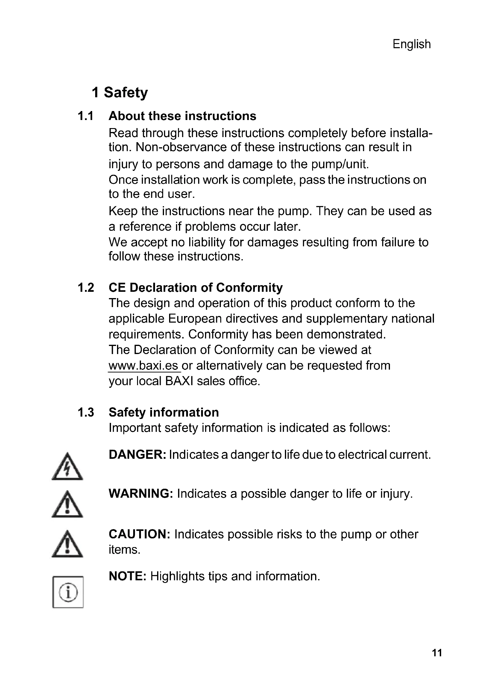
3.2 Functions (Fig. 2)
Valves
The SB-4X is equipped with a non-return valve (1) on the pressure side and with a stop valve (2) on the suction side. When exchanging the motor head (3), it is sufficient to cut the power by unplugging the connector (5) and to close the stop valve at the rotating slot (4). The motor head can then be simply unscrewed → Page 16.
4 Installation and electrical connection
4.1 Mechanical Installation
DANGER: Before starting work, make sure that the pump has been disconnected from the power supply.
Installation site (Fig. 3)
Provide a weatherproof, frost-free, dust-free and well-ventilated room for the installation. Choose an installation site that is easily accessible.

CAUTION: Dirt can cause the pump to fail. Flush the pipe system before installation.

NOTE: The stop valve and non-return valve are pre-installed.
-
Prepare the installation site so that the pump can be installed without being exposed to mechanical stresses.
-
Choose the right installation position - only as shown in (Fig. 3 A). The arrow on the back of the housing indicates the direction of flow.
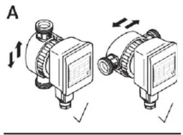
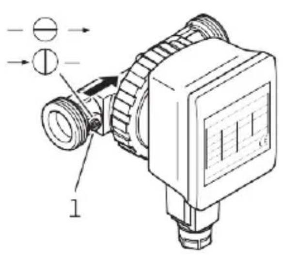
Turn the motor head or remove it (Fig. 4)
- Release the union nut - unscrew it completely if necessary.

CAUTION: Do not damage the housing seal. Replace damaged seals.
- Turn the motor head so that the connector points downwards.

CAUTION: If the position is wrong, water can penetrate and destroy the pump.
- Tighten the union nut again.
Open the stop valve (Fig. 5)
- Turn slot (1) with a screwdriver so that it is parallel to the direction of flow.

NOTE: To close, turn the slot so that it is across the direction of flow.
- Fit the thermal insulation shell.

CAUTION: The plastic parts of the motor may not be heat-insulated in order to protect the pump from overheating.
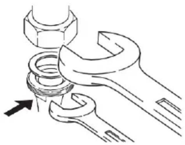
Connecting (Fig. 6)
- Connect the pipework.

CAUTION: For the versions with stop and non-return valves, these are already pre-installed and sealed with a tightening torque of 15 Nm (hand-tight). Screwing with excessive tightening torque destroys the valve screw connection and the O ring. When installing the valve, use a fixed spanner to prevent twisting.
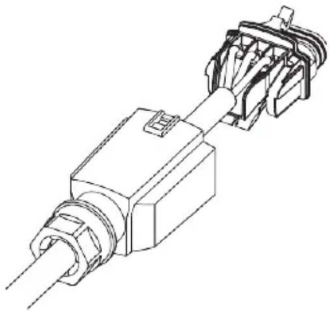
4.2 Electrical connection
DANGER: Only a qualified electrician is allowed to work on the electrical connection. Before establishing the connection, make sure that the connecting cable is dead.
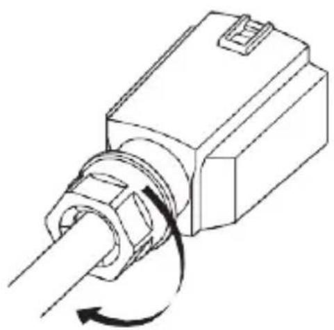
Establish the electrical connection as follows: (Fig. 7a - Fig. 7e)
Open the connector as follows: (Fig. 8)
4.3 Filling and venting
- Fill the system
- The pump rotor space vents automatically after a short time in operation. This may cause noises. If necessary, switch off and on repeatedly to accelerate the bleeding. Dry running for short periods will not harm the pump.
5 Maintenance/faults
Cleaning
Clean the outside of the pump with a slightly damp cloth only. Do not use detergents.
Replacing the motor head

WARNING: When removing the motor head or pump, hot fluid may spurt out under high pressure. Allow the pump to cool down beforehand.
Close the stop valves before removing the pump → Page 16.

NOTE: When the motor is removed and running, noises and a change in rotation may occur. This is normal for this situation.
Faultless operation can only be guaranteed when the pump is operated in fluid.
Replacing the motor head → Page 16.
Order the service motor from a specialist retailer.
| Faults | Causes | Remedies |
| Pump does not start. | Interruption in the power supply, short- circuit or defective fuses. | Have the power supply checked by a qualified electrician. |
| Motor is blocked, e.g. by deposits from the water mains. | Have the pump removed by a qualified technician → Page 16. Check that the impeller can move by turning it and rinse out the dirt that has accumulated. | |
| Pump is making noises. | Motor scraping, e.g. through deposits from the water mains. | |
| Running dry, too little water. | Check the check valves, they must be fully open. | |
| Air in the pump. | Switch the pump on/off 5 times for 30 s in each case. |

NOTE: If you cannot remedy the fault, contact a specialist retailer.
6 Disposal
Damage to the environment and risks to personal health are avoided by the proper disposal and appropriate recycling of this product.
- Use public or private disposal organisations when disposing of the entire product or part of the product.
- For more information on proper disposal, please contact your local council or waste disposal office or the supplier from whom you obtained the product.
1 Sécurité
2.2 Raccordements (Fig. 1)
SB-4X

- Safety
- About these instructions
- CE Declaration of Conformity
- Safety information
- Qualification
- Regulations
- Conversion, spare parts
- Transport
- Electrical current
- Technical Data
- Type key
- Connections (Fig. 1)
- Data
- Scope of delivery
- Principle of operation
- Application
- Functions (Fig. 2)
- Valves
- Installation and electrical connection
- Mechanical Installation
- Installation site (Fig. 3)
- Turn the motor head or remove it (Fig. 4)
- Open the stop valve (Fig. 5)
- Connecting (Fig. 6)
- Electrical connection
- Filling and venting
- Maintenance/faults
- Cleaning
- Replacing the motor head
- Disposal
- Sécurité
- Raccordements (Fig. 1)
Brand : Baxi
Model : SB50 XA
Category : Pump