
DS720 - Rammer Wacker Neuson - Free user manual and instructions
Find the device manual for free DS720 Wacker Neuson in PDF.
| Product type | Rammer (vibratory tamper) |
| Brand | Wacker Neuson |
| Model | DS720 |
| Engine | Yanmar L40AE-D WK2, single-cylinder 4-stroke air-cooled diesel |
| Rated power | 4.2 hp (3.1 kW) |
| Rotation speed (full load) | 3600 rpm |
| Rotation speed (idle) | 1200 ±200 rpm |
| Operating weight | 75 kg |
| Fuel tank capacity | 5.7 L |
| Fuel consumption | 0.9 L/h |
| Engine oil capacity | 800 ml |
| Rammer system oil capacity | 890 ml |
| Impact energy | 100 J (per blow) |
| Stroke of impact plate | Up to 75 mm |
| Impact speed | 56 blows/min (adjustable) |
| Sound pressure level (at ear) | 92 dB(A) |
| Sound power level | 103 dB(A) |
| Vibration (hand/arm acceleration) | 16 m/s² |
| Areas of use | Soil compaction, trenches, stabilization, road repair, foundations |
| Safety | Hearing protection required, avoid confined spaces, do not touch hot muffler |
| Routine maintenance | Check oil, air filter, tighten screws, clean fins |
| Recommended fuel | Diesel No. 2, cetane index >45 |
| Engine lubrication | SAE CC oil or better |
| Rammer system lubrication | SAE 30 oil |
| Spare parts | Available from Wacker Neuson (references in the manual) |
Frequently Asked Questions - DS720 Wacker Neuson
User questions about DS720 Wacker Neuson
0 question about this device. Answer the ones you know or ask your own.
Ask a new question about this device
Download the instructions for your Rammer in PDF format for free! Find your manual DS720 - Wacker Neuson and take your electronic device back in hand. On this page are published all the documents necessary for the use of your device. DS720 by Wacker Neuson.
USER MANUAL DS720 Wacker Neuson
1730 ASSE-MOLLEM 1730 ASSE-MOCEM
4040 Herstal 4 Avenue
This manual is divided into the sections listed below:
Diesel engine exhaust, some of its constituents, and certain vehicle components contain or emit chemicals known to the State of California to cause cancer and birth defects or other reproductive harm.
1040SD70
This manual provides information and procedures to safely operate and maintain this WACKER model. For your own safety and protection from injury, carefully read, understand and observe the safety instructions described in this manual. THE INFORMATION CONTAINED IN THIS MANUAL WAS BASED ON MACHINES IN PRODUCTION AT THE TIME OF PUBLICATION. WACKER CORPORATION RESERVES THE RIGHT TO CHANGE ANY PORTION OF THIS INFORMATION WITHOUT NOTICE.
A nameplate listing the Model Number, Item Number, Revision, and Serial Number is attached to each unit. Please record the information found on this plate so it will be available should the nameplate become lost or damaged. When ordering parts or requesting service information, you will always be asked to specify the model, item number, revision number, and serial number of the unit.
This machine may be covered by one or more of the following patents:
WACKER MACHINES PROTECTED BY ONE OR MORE OF THESE U.S. PATENTS:
4643611; 4555238; 5564375; 5586630; 4419048
111891
PATENT PENDING
Keep this manual or a copy of it with the machine. If you lose this manual or need an additional copy, please contact WACKER Corporation. This machine is built with user safety in mind, however, it can present hazards if improperly operated and serviced. Follow operating instructions carefully! If you have questions about operating or servicing this equipment, please contact WACKER Corporation.
1.1 Safety Information 1A-2
1.2 Operating Safety.... 1A-3
1.3 Operator Safety while using Internal Combustion Engines 1A-4
1.4 Service Safety 1A-4
1.5 Sound Measurements.... 1A-5
1.6 Vibration Measurements 1A-5
1.7 Technical Data 1A-5
1.8 Safety & Informational Labels 1A-6
1.9 Operating Labels 1A-7
1.10 Dimensions 1A-8
1.11 Description 1A-8
1.12 Recommendations on compaction.... 1A-9
1.13 Transportation 1A-9
1.14 Recommended Fuel 1A-10
1.15 Before Starting.... 1A-10
1.16 To Start.... 1A-10
1.17 Operation 1A-10
1.18 To Stop 1A-10
1.19 Proper Compaction.... 1A-11
1.20 Periodic Maintenance Schedule 1A-11
1.21 Servicing Air Cleaner 1A-12
1.22 Lubrication 1A-13
1.23 Shoe Hardware 1A-14
1.24 Long-Term Storage.... 1A-14
1.25 Troubleshooting 1A-14
1.1 Safety Information
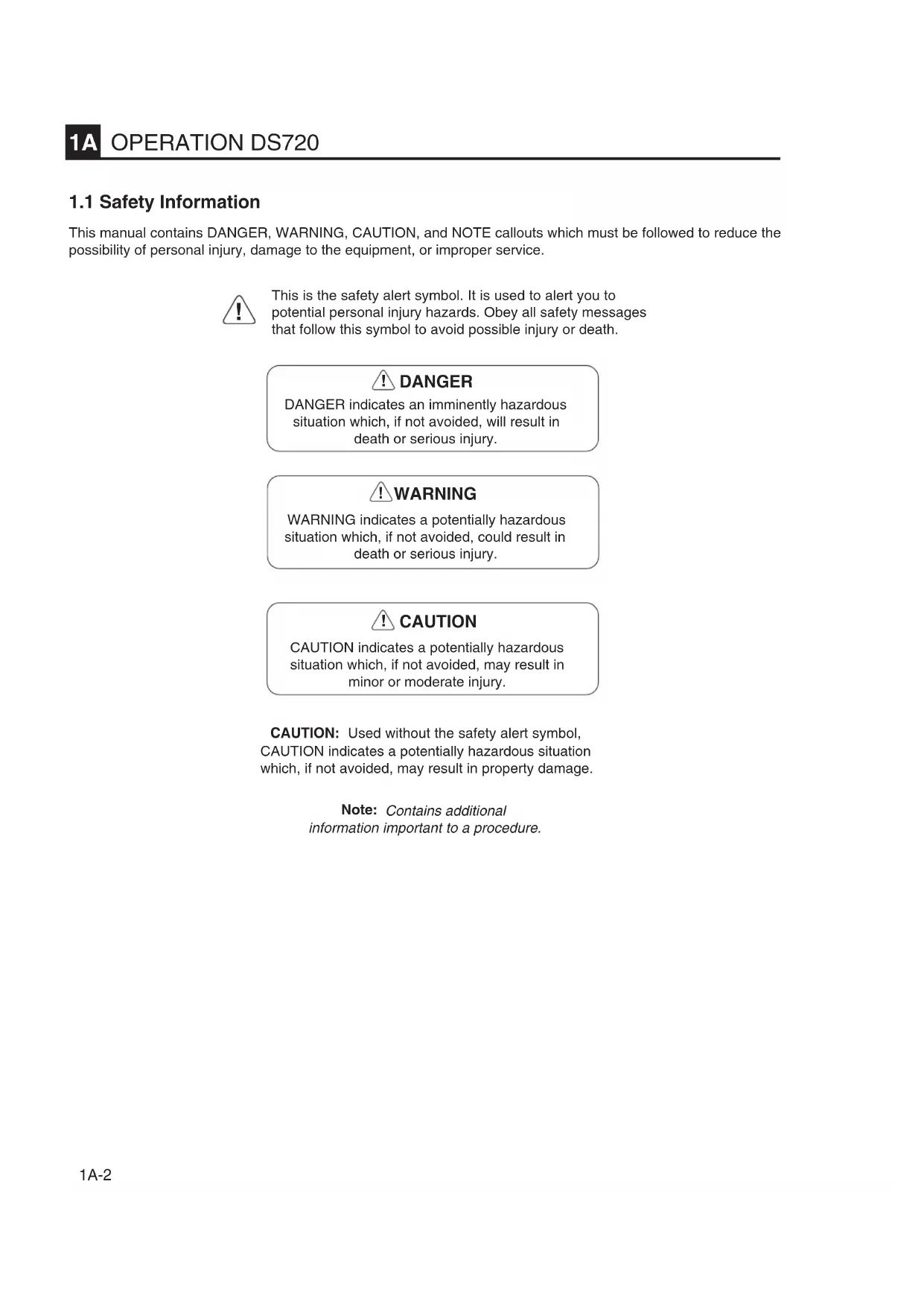
This manual contains DANGER, WARNING, CAUTION, and NOTE callouts which must be followed to reduce the possibility of personal injury, damage to the equipment, or improper service.

This is the safety alert symbol. It is used to alert you to potential personal injury hazards. Obey all safety messages that follow this symbol to avoid possible injury or death.

DANGER
DANGER indicates an imminently hazardous situation which, if not avoided, will result in death or serious injury.

WARNING
WARNING indicates a potentially hazardous situation which, if not avoided, could result in death or serious injury.

CAUTION
CAUTION indicates a potentially hazardous situation which, if not avoided, may result in minor or moderate injury.
CAUTION: Used without the safety alert symbol, CAUTION indicates a potentially hazardous situation which, if not avoided, may result in property damage.
Note: Contains additional information important to a procedure.
1.2 Operating Safety
Familiarity and proper training are required for the safe operation of equipment! Equipment operated improperly or by untrained personnel can be dangerous! Read the operating instructions and familiarize yourself with the location and proper use of all instruments and controls. Inexperienced operators should receive instruction from someone familiar with the equipment before being allowed to operate the rammer.
! WARNING
NEVER operate rammer in applications for which it is not intended.
NEVER allow improperly trained personnel to operate rammer.
NEVER touch hot muffler, engine cylinders, or cooling fins. Burns will result.
NEVER use accessories or attachments which are not recommended by WACKER for rammer. Damage to rammer and/or injury to user may result.
NEVER leave a running machine unattended.
NEVER run machine indoors or in an enclosed area such as a deep trench unless adequate ventilation is provided. Exhaust gas from the engine contains poisonous carbon monoxide gas; exposure to carbon monoxide can cause loss of consciousness and may lead to death. WACKER offers electric rammers for applications in enclosed areas.
NEVER tamper with or disable the function of operating controls.
ALWAYS read, understand, and follow procedures in Operator's Manual before attempting to operate equipment.
ALWAYS be sure that all other persons are at a safe distance from the rammer. Stop the machine if people step into the working area of the machine.
ALWAYS be sure operator is familiar with proper safety precautions and operation techniques before using rammer.
ALWAYS wear protective clothing when operating rammer. Wear goggles or safety glasses, hearing protection, and safety shoes.
ALWAYS keep hands, feet, and loose clothing away from moving parts of rammer.
ALWAYS use common sense and caution when operating rammer.
ALWAYS be sure rammer will not tip over, roll, slide, or fall when not being operated.
ALWAYS turn engine OFF when rammer is not being operated.
ALWAYS guide the rammer in such a way that the operator is not squeezed between the rammer and solid objects. Special care is required when working on uneven ground or when compacting coarse material. Make sure to stand firmly when operating the machine under such conditions.
ALWAYS operate the rammer in such a way that there is no danger of it turning over or falling in, when working near the edges of breaks, pits, slopes, trenches and platforms.
1.3 Operator Safety while using Internal Combustion Engines
Internal combustion engines present special hazards during operation and fueling! Failure to follow the safety guidelines described below could result in severe injury or death.
! DANGER
DO NOT smoke while operating rammer.
DO NOT operate rammer near open flames.
DO NOT smoke when refueling engine.
ALWAYS refill fuel tank in well-ventilated area.
DO NOT refuel hot or running engine.
ALWAYS replace fuel tank cap after refueling.
DO NOT refuel engine near open flame.
ALWAYS check fuel lines, fuel cap, and fuel tank for leaks and cracks before starting engine. Do not run machine if fuel leaks are present, or fuel cap or fuel lines are loose.
DO NOT spill fuel when refueling engine.
1.4 Service Safety
Poorly maintained equipment can become a safety hazard! In order for the equipment to operate safely and properly over a long period of time, periodic maintenance and occasional repairs are necessary.
! WARNING
DO NOT attempt to clean or service rammer while it is running.
ALWAYS replace safety devices and guards after repairs and maintenance.
DO NOT operate rammer with safety devices or guards removed or not in working order.
ALWAYS keep area around muffler free of debris in order to reduce the chance of an accidental fire.
DO NOT operate rammer without air cleaner.
ALWAYS do Periodic Maintenance as recommended in Operator's Manual.
DO NOT remove air cleaner paper element, precleaner, or air cleaner cover while operating rammer.
ALWAYS clean debris from engine cooling fins.
DO NOT alter engine speeds. Run engine only at speeds specified in Technical Data Section.
ALWAYS replace worn or damaged components with original spare parts designed and recommended by WACKER for servicing this rammer.
1.5 Sound Measurements
The operating sound levels, measured per the requirements of Appendix 1, Paragraph 1.7.4.f of the EC-Machine Regulations, are:
- the sound pressure level at operator's location ( L_pA ) = 92 dB(A).
- the sound power level ( L_WA ) = 103 dB(A).
These sound values were determined according to ISO 3744 for the sound power level ( L_WA ) and ISO 6081 for the sound pressure level ( L_pA ) at the operator's location.
1.6 Vibration Measurements
The operating hand/arm vibration level, measured per the requirements of enclosure 1, Paragraph 2.2 or 3.6.3 of the EC-Machine Regulations, is approximately 16 m/s^2 .
The weighted effective acceleration value was determined according to ISO 8662 Part 1.
The sound and vibration measurements were obtained with the machine operating on crushed gravel at nominal engine speed.
1.7 Technical Data
| ledom/ekamenignE 2KWDABHnaY | ||
| Engine type | air cooled, single-cylinder, 4-stroke diesel engine | |
| Engine power | Hp (kW) | 4.2 (3.1) |
| Engine speed - full | rpm | 3600 |
| Engine speed - idle | rpm | 1200 ± 200 |
| Engine speed - clutch engagement | rpm | 2000 ± 200 |
| Valve clearance - cold | in. (mm) | 0.006 (0.15) |
| Engine lubrication | oil grade | CC or better (1) |
| Engine oil capacity | oz. (ml) | 27 (800) |
| Piston displacement | cm3 | 199 |
| Fuel type | No. 2 Diesel, cetane > 45 | |
| Fuel tank capacity | gal. (l) | 1.5 (5.7) |
| Fuel consumption | gal./hr. (l/h) | 0.25 (0.9) |
| Operating weight | lbs. (kg) | 165 (75) |
| Percussion rate (2) | strokes/min. | 650–700 |
| Single stroke work | J/mkp | 100 |
| Stroke of the ramming shoe (up) | in. (mm) | to 3 (75) |
| Ramming system lubrication | oil grade | SAE 30 |
| Ramming system oil capacity | oz. (ml) | 30 (890) |
(1) Refer to Section 1.22 Lubrication.
(2) Percussion rate can be adjusted with the throttle lever.
1.8 Safety & Informational Labels
This WACKER machine uses international pictorial labels where needed. These labels are described below:
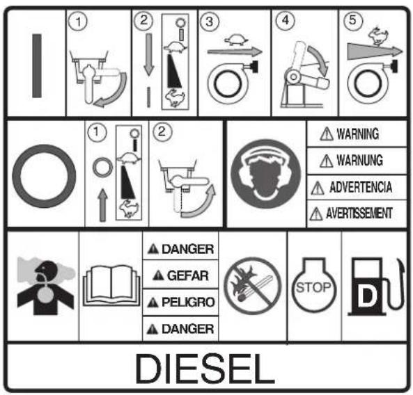
This molded-in label contains important safety and operating information. If it becomes illegible, the cover must be replaced. Refer to the Parts Book for ordering information.
112419-6
Label Meaning Label Meaning
 | Danger of asphyxiation! |  | Read operator's manual for machine information. |
 | No sparks, flames, or burning objects near fuel tank. |  | Stop engine before fueling. |
 | Diesel fuel. |  | Wear hearing protection when operating machine. |
 Hot surface!Replace guard!115414 Hot surface!Replace guard!115414 | |||
1.9 Operating Labels
This WACKER machine uses international pictorial labels where needed. These labels are described below:

flowchart
graph LR
    A["①"] --> B["②"]
    B --> C["③"]
    C --> D["④"]
    D --> E["⑤"]

112419-6b
112419-6c
Label Meaning
 | Turn fuel valve to the “open” position. | 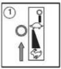 | Place throttle control lever in the “stop” position |
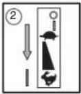 | Place throttle control lever in the “start” position. | 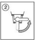 | Turn fuel valve to the “closed” position. |
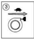 | Slowly pull rewind starter. | [GTXG6] | Throttle control lever:Stop |
 | Press decompression lever down. | Start / Idle | |
| [5] | Quickly pull rewind starter. |  | Run 11541689366 |
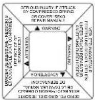 | WARNING! Serious injury if struck by compressed spring or cover. If the spring system cover is removed improperly, the springs can eject. | ||
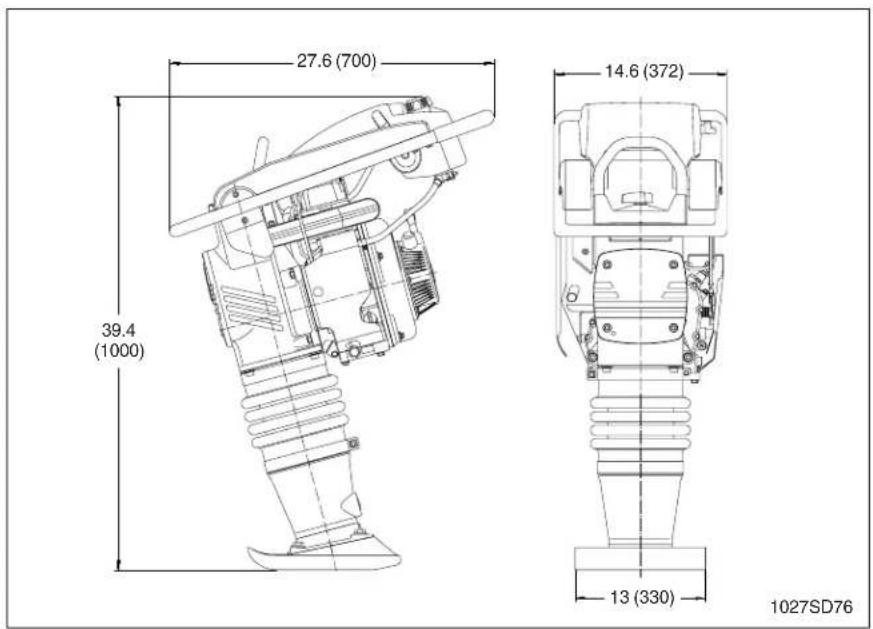
1.10 Dimensions
in. (mm)
1.11 Description
Applications
• Civil engineering jobs for the compaction of all types of soils, especially cohesive soils.
- Trenches for cables, water lines, gas pipelines, backfills and structural fills, etc.
• Stabilization of slopes, dams, dikes and levees.
• Road construction for the compaction of base course concrete, marginal strip and sub-surface compaction jobs.
• Road repairs of all types.
• Building construction for the compaction of concrete and sub-soils in cellars and shed floors.
- Garden construction and parks for the stabilization of roads and paths.
Description of function
The vibration required for compaction is produced by the ramming system, which is firmly attached to the ramming shoe.
The engine, which is flanged to the crankcase and is held in place by four screws, drives the ramming system over a gear transmission and a connecting rod. The engine torque is transmitted by means of a centrifugal clutch.
The centrifugal clutch interrupts the flow of power to the ramming system at low engine speeds, thus allowing for a perfect idling of the engine. The advance movement in forward direction of the rammer is ensured by means of the tilt of the ramming system.
The engine can be switched off with the throttle control.
The drive engine works according to the diesel principle, and is started mechanically by means of a recoil starter. The engine is air cooled and the air necessary for combustion is directed through a precleaner and a dry-type air filter.
The guide handle and frame are mounted on the ramming system with a set of shockmounts, therefore assuring a minimum transmission of vibrations to the hands of the operator.
1.12 Recommendations on compaction
Soil conditions:
The maximum compaction depth of the soil depends on several factors relating to the nature of the soil, such as water content, grain-size distribution, etc. It is therefore not possible to specify a given layer depth.
Recommendation: In each case determine the maximum possible compaction depth through compaction tests and soil samples.
1.13 Transportation
-
Always shut off the engine and close the fuel valve when transporting the rammer.
-
Use lifting equipment with minimum lifting capacity of 220.5 lbs. (100 kg).
-
Use the central lifting point (a) when lifting the rammer.
-
WACKER recommends transporting rammers upright whenever possible; however, a rammer should not be allowed to fall over.
If the rammer cannot be secured in the upright position, tie down the rammer to the transport vehicle to prevent it from tipping, falling, or rolling. Lay the rammer down only as shown below and tie it to the vehicle at points (b) and (c).
CAUTION: Drain the fuel tank as required to prevent fuel leaking from the cap (d).
CAUTION: After transporting the rammer horizontally, upright the rammer and allow the oil to drain back through the engine. It may take up to 45 minutes for the oil level to recover. Failure to do so may result in engine damage.
Note: Refer to the specifications in the safety instructions.

1A
1.14 Recommended Fuel
Use only pure diesel fuel. Close the fuel cap immediately. It is important to maintain cleanliness to avoid problems with the fuel injection system, and to prevent premature clogging of the fuel filter. To avoid contamination, DO NOT open the fuel line or the fuel pump or any other point of the fuel system, not even to bleed air. The fuel pump will bleed automatically. This applies even if the fuel tank was run dry. If this happens, refill the fuel tank.
1.15 Before Starting
- Read safety instructions at the beginning of this manual.
- Perform daily maintenance items.
- Place rammer on loose soil or gravel. DO NOT start rammer on hard surfaces such as asphalt or concrete.
1.16 To Start
- Turn the fuel valve to the "0" (open) position.
- Open the throttle control lever to the "start" position.
- Slowly pull the recoil starter rope handle until resistance is met, then release.
- Press down on the decompression lever. (When pulling the recoil starter rope, the decompression lever will automatically return to initial position).
- Quickly pull the recoil starter rope.
1.17 Operation
Keep vibratory rammer clean and dry. Avoid no-load strokes. Never allow the rammer to run full throttle when forcing away material or when lifting the equipment.
CAUTION: To prevent damage to the rammer, do not allow the rammer to run on its side.
If the rammer should tip on its side, place the rammer in the position shown below, then shut off the engine by moving the throttle control lever through the detent to the off position.
Note: The rammer may continue to run for 5–10 seconds after the throttle is placed to off, then the engine will stop.

natural_image
Technical line drawing of a mechanical device with no visible text or symbols1.18 To Stop
Switch off the engine as follows:
CAUTION: Do not switch off engine by means of the decompression lever.
- Reduce engine rpm's and let it run for a short while.
CAUTION: Do not switch off engine directly from full power. - Shut off the engine by moving the throttle control lever through the detent to the off position. The engine will stop.
- Close the fuel valve.
Note: For short-term operation interruption, it is only necessary to stop the engine.
1.19 Proper Compaction
- Run the rammer at the full throttle position for maximum performance.
- Guide the rammer with its handle. Allow machine to pull itself forward. DO NOT try to over-power the machine.
- For best compaction, the shoe must hit the ground flat (a), not on its toe or heel. This will save on excessive shoe wear.

1.20 Periodic Maintenance Schedule
| eludehcSe | yDa nea m grits | Aft fits aoh | yrev kee o52 aoh | vE | yrev htn 001 aoh | vE om | yrev sht 003 aoh | vE nom | yrev sht 005 aoh |
| Check fuel level | • | ||||||||
| Check engine oil level | • | ||||||||
| Check rammer oil in sightglass | • | ||||||||
| Check fuel line, cap, and fittings for leaks aoks | • | ||||||||
| Check bellows for damage and fit | • | ||||||||
| Tighten ramming shoe hardware | • | • | |||||||
| Check and tighten engine cylinder screws | • | • | |||||||
| Check and tighten external hardware | • | • | |||||||
| Clean engine cooling fins | • | ||||||||
| Change engine oil (1) | • | ||||||||
| Clean engine oil filter (1) | • | ||||||||
| Clean recoil starter | • | ||||||||
| Change ramming system oil (1) | • | ||||||||
| Check and adjust valve clearance | • (1st) | • | |||||||
| Replace engine oil filter | • | ||||||||
| Check fuel filter, clean or replace | • |
(1) Perform initially after first 50 hours of operation.
Note: If engine performance is poor, check, clean, and replace air filter elements as needed.
1.21 Servicing Air Cleaner
Under normal operating conditions the air cleaner elements will not require cleaning and should not be removed from the machine. If the elements do become plugged with dirt, the engine will begin to lose power. In this case, the elements can be removed and cleaned as described below. Replace an element if it becomes so plugged with dirt it can no longer be cleaned.
CAUTION: NEVER run engine without air cleaner. Severe engine damage will occur.
! WARNING
NEVER use gasoline or other types of low flash point solvents for cleaning the air cleaner. A fire or explosion could result.
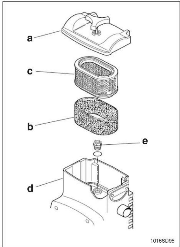
The engine is equipped with a dual element air cleaner.
-
Remove air cleaner cover (a). Remove precleaner and paper element and inspect them for holes or tears. Replace if damaged.
-
Precleaner (b):
Clean with low-pressure compressed air. When very soiled, wash in solution of mild detergent and warm water. Rinse thoroughly in clean water. Allow to dry thoroughly before re-installing.
Note: Do not oil precleaner.
- Paper element (c)
Tap element lightly to remove excess dirt. Replace paper element if it appears heavily soiled.
- Wipe out filter housing (d) with a clean rag.
CAUTION: Do not allow dirt into the engine intake port while cleaning—damage to the engine will result.
1.22 Lubrication
Engine oil
Check oil level:
Tilt the machine backwards approx. 15^ until the engine is level by placing a wedge under the shoe. The oil surface should reach NO HIGHER THAN the bottom of the filler neck "H", but no lower than "L" (see drawing) or visible on the dipstick (f) when it is inserted (not screwed) into the filler neck.
Add CC or better quality oil through the filler neck as required.
CAUTION: DO NOT overfill. The oil level should just reach the bottom of the filler neck. Too much oil can cause damage to the engine and the rammer.
Note: After transporting the rammer horizontally, upright the rammer and allow the oil to drain back through the engine. It may take up to 45 minutes for the oil level to recover.
Oil change:
- Let the engine warm up, then shut it off.
- Place the rammer so that the engine is level.
- Unscrew the engine oil drain plug (g) and let oil flow out.
- Screw in the oil drain plug.
- Fill with approx. 27 oz. (800 ml) of oil through the oil fill opening. Refer to Check oil level, above.
Oil filter:
- Drain the oil as above.
- Unscrew the bolt (h) on the oil filter cover and pull out the oil filter.
To clean the oil filter:
Use low pressure compressed air to remove any visible debris on the oil filter.
To replace the oil filter:
Discard the old oil filter in accordance with environmental regulations. Replace with WACKER-supplied oil filter and O-ring.
Ramming system
Check oil level:
- Place the rammer so it is resting on its shoe.
- Check the oil level through oil sightglass (j).
- If the oil is not visible, refill through the oil fill opening (e) with HD brand quality SAE 40 oil.
- Close the oil fill opening.

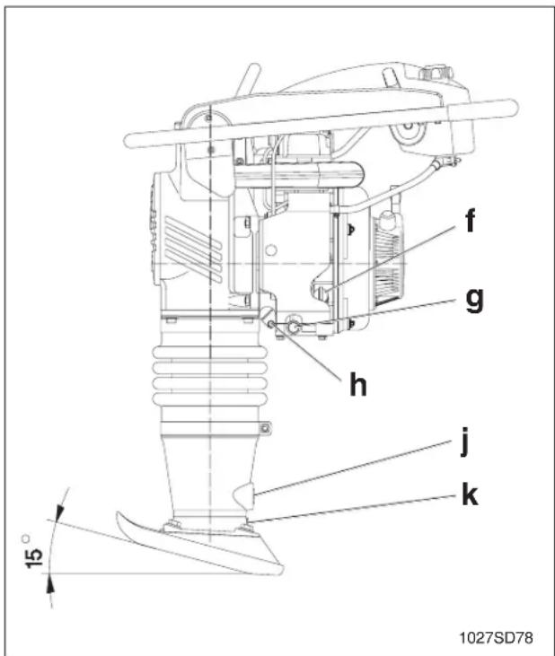
Oil change:
- Unscrew the oil drain plug (k) located below the oil sightglass.
- Tip the rammer over and allow oil to drain.
- Screw in the oil drain plug.
- Remove the oil fill plug (e) located at the top of the crankcase. Fill with 30 oz. (890 ml) HD brand quality SAE 40 oil through the oil fill opening.
- Screw in the oil fill plug.
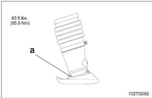
1.23 Shoe Hardware
On new machines, or after replacing shoe, check and tighten shoe hardware (a) after the first 5 hours of operation. Inspect hardware every week thereafter.
Torque hardware as specified.
1.24 Long-Term Storage
- Drain fuel from the fuel tank.
- Start the engine and run it until remaining fuel is used.
- Cover the rammer and store in a clean, dry location.
1.25 Troubleshooting
| Problem / Symptom | Reason / Remedy |
| Engine does not start, or stalls. | 1. No fuel in tank.2. Fuel valve closed. |
| Engine does not accelerate, is hard to start, or runs erratically. | 1. Crankshaft seals are leaking.2. Air cleaner may be clogged. |
| Engine overheats. | 1. Clean cooling fins and fan blades. |
| Engine runs; rammer does not tamp. | 1. Inspect clutch for damage. Replace if necessary.2. Broken connecting rod or crankgear.3. Low engine performance. Compression loss. |
| Engine runs, rammer operation is erratic. | 1. Oil/grease on clutch.2. Broken/worn springs.3. Soil buildup on ramming shoe.4. Broken parts in ramming system or crankcase.5. Engine operating speed is too high. |
Inhaltsverzeichnis
112419-6b
112419-6c
Symbol Erklärung
natural_image
Technical line drawing of a mechanical device with no visible text or symbols1.18 Abstellen
112419-6b 112419-6c
natural_image
Technical line drawing of a mechanical device with no visible text or symbols112419-6b
112419-6c
Pictogramme Signification
natural_image
Technical line drawing of a mechanical device with no visible text or symbolsPart Numbers appearing in boldface type are recommended spare parts. This means that these parts are subject to wear under normal operating conditions and may require periodic service or replacement. It is recommended that these items be stocked to meet the expected service requirements of this model. Actual stocking quantities of these and other parts used in more extensive repairs will depend on the service practices of each customer.
[L1] Indicates a sealant or threadlocking compound to be used when assembling part. Refer to Sealant Chart at end of manual for description of sealants.
[T1] Indicates the correct torque value for assembling part. Refer to Torque Chart at end of manual for standard torque measurements.
1028SD09
| Ref. | Part No. | Qty. | Description | Beschreibung | Descripción | Description |
| 1 01 | 11765 1 Cover-silencing Deckel Tapa Couvercle | |||||
| 2 00 | 10622 2 Washer Scheibe Arandela | Rondelle | ||||
| 3 | 0010367 | 3 | Nut-lock | Sicherungsmutter | Contratuerca | Contre-écrou |
| 4 00 | 10624 3 Washer B6.4 Scheibe Arandela | Rondelle | ||||
| 5 | 0011551 | 2 | Screw M6x20 | Schraube | Tornillo | Vis |
| 6 | 0107171 | 1 | Tank-fuel cpl. | Kraftstofftank | Tanque de combustible carburant | Réservoir de |
| 7 | 0074552 | 2 | Clamp .390 | Schelle | Abrazadera | Agrafe |
| 8 00 | 33198 1 Washer Scheibe Arandela | Rondelle | ||||
| 9 01 | 05194 1 Washer M8x1.5" Scheibe Arandela | Rondelle | ||||
| 10 | 0111202 | 1 | Control | Betätigung | Gobierno | Commande |
| 11 00 | 10622 1 Washer Scheibe Arandela | Rondelle | ||||
| 12 | 0011341 | 1 | Screw M8x40 | Schraube | Tornillo | Vis |
| 13 | 0108414 | 1 | Mount-throttle control | Konsole | Ménsula | Console |
| 14 | 0012360 | 1 | Screw M8x12 | Schraube | Tornillo | Vis |
| 15 | 0108200 | 1 | Cable-throttle | Kabel | Cable | Câble |
| 16 | 0106103 | 1 | Tube-air duct | Luftstutzen | Adaptador de aire | Pipe d'air |
| 17 | 0078844 | 2 | Clamp | Schelle | Abrazadera | Agrafe |
| 18 01 | 07462 1 Hose-fuel return Kraftstoffleitung | Manguera | Tuyau | |||
| 19 | 0118381 | 1 | Engine | Motor | Motor | Moteur |
| 20 | 0096087 | 4 | Nut M10 | Mutter | Tuerca | Ecrou |
| 21 | 0112077 | 1 | Handle-crane lift | Tragegriff | Manija de levante | Poignée de relèvement |
| 22 | 0023619 | 4 | Screw M8x12 | Schraube | Tornillo | Vis |
| 23 | 0114798 | 1 | Guide handle compl. | Führungsbügel kompl. | Manija compl. | Poignée compl. |
| 24 | 0011543 | 6 | Screw M8x20 | Schraube | Tornillo | Vis |
| 25 01 | 05056 2 Shockmount, special Puffer | Amortiguador | Silentbloc | |||
| 26 | 0058498 | 1 | Plate-protection | Schutzplatte | Placa de protección | Plaque de protection |
| 27 | 0087023 | 2 | Screw M6x16 | Schraube | Tornillo | Vis |
| 28 | 0058381 | 8 | Washer-lock | Federring | Disco de resorte | Rondelle de ressort |
| 29 | 0011553 | 8 | Screw M6x16 | Schraube | Tornillo | Vis |
| 30 | 0010368 | 2 | Nut-lock | Sicherungsmutter | Contratuerca | Contre-écrou |
T1 - 58 ft.lbs. (79 Nm)
2.5 13" Ramming shoe / 330mm Stampfeinsatz / Placa de pisón 330mm / Sabot de frappe 330mm
![[T1] 6 [T2] 7 8 9 10 11 4 5 1003SD87](/content/2026/04/589660/images/35739158a6a0eca6a6e885f46cd6368923a98989ce652865aba2a071da008713.jpg)
| Ref. | Part No. | Qty. | Description | Beschreibung | Descripción | Description |
| 1 | 0072069 | 1 | Kit-ramming shoe (incl. 2–11) | Stampfeinsatz kpl. (inkl. 2–11) | Placa de pisón compl. (incl. 2–11) | Sabot de frappe compl. (incl. 2–11) |
| 2 | 0010366 | 4 | Nut-lock M12 | Sicherungsmutter | Contratuerca | Contre-écrou |
| 4 | 0011157 | 2 | Bolt-plow M12x80 | Senkschraube | Tornillo avellanado | Vis à tête fraisée |
| 5 | 0047987 | 2 | Bolt-plow M12x105 | Senkschraube | Tornillo avellanado | Vis à tête fraisée |
| 6 | 0010367 | 13 | Nut | Mutter | Tuerca | Ecrou |
| 7 | 1005118 | 13 | Washer | Scheibe | Arandela | Rondelle |
| 8 | - | 1 | Plate-bottom | Schleißplatte | Placa de desgaste | Plaque d'usure |
| 9 | 0011194 | 4 | Bolt-plow M8x40 | Senkschraube | Tornillo avellanado | Vis à tête fraisée |
| 10 | 0011193 | 4 | Bolt-plow M8x45 | Senkschraube | Tornillo avellanado | Vis à tête fraisée |
| 11 | 0011192 | 5 | Bolt-plow M8x50 | Senkschraube | Tornillo avellanado | Vis à tête fraisée |
T1 - 58 ft.lbs. (79 Nm) T2 - 18 ft.lbs. (24 Nm)
2.6 Ramming system / Stampfsystem / Sistema apisonador / Système du pilon
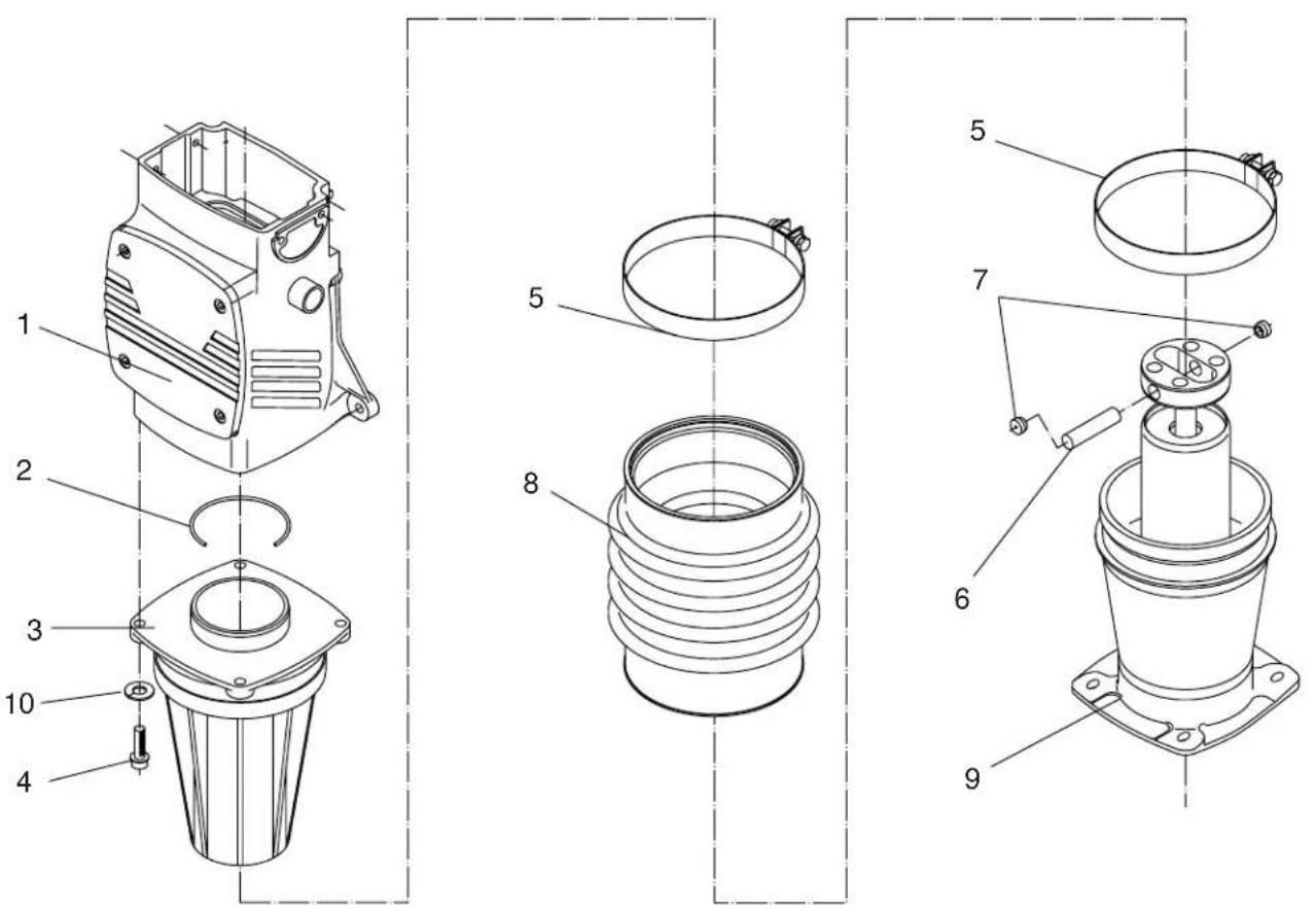
1028SD12
| Ref. | Part No. | Qty. | Description | Beschreibung | Descripción | Description |
| 1 | - | 1 | Crankcase cpl. | Kurbelgehäuse | Cárter | Carter |
| 2 003 | 1880 1 O-Ring O-Ring | Anillo-O | Joint torique | |||
| 3 | 0088842 | 1 | Cylinder- guide | Führungszylinder | Cilindro de guía | Cylindre de guidage |
| 4 001 | 1533 4 Screw M10x35 Schraube | Tornillo | Vis | |||
| 5 | 2006976 | 2 | Clamp 7" | Schelle | Abrazadera | Agrafe |
| 6 | 0039785 | 1 | Pin-piston mount | Kolbenbolzen | Pasador de pistón | Axe de piston |
| 7 | 1006925 | 2 | Plug .640 | Schraubverschluß | Tapón roscado | Bouchon |
| 8 | 1006882 | 1 | Bellows | Faltenbalg | Fuelle | Soufflet |
| 9 | - | 1 | Spring cylinder | Federzylinder | Cilindro de resorte | Cylindre de ressort |
| 10 | 0010644 | 4 | Washer-lock | Federring | Disco de resorte | Rondelle de ressort |
| Ref. | Part No. | Qty. | Description | Beschreibung | Descripción | Description |
| 1 01 | 10586 1 Bushing | Buchse Buje Douille | ||||
| 2 | 0111482 | 1 | Fitting-filter, fuel | Verschraubung | Unión | Raccord |
| 3 | 0104093 | 1 | Cap-fuel tank | Tankdeckel | Tapa del tanque | Chapeau de réservoir |
| 4 | 0095950 | 1 | Filter-fuel | Kraftstofffilter | Filtro de combustible | Filtre à carburant |
| 5 | 0095949 | 1 | Valve-fuel | Kraftstoffhahn | Grifo de combustible | Robinet de carburant |
| 6 0073617 2 Nut M6 | Mutter | Tuerca | Ecrou | |||
| 7 | 0016836 | 2 | Clamp | Schelle | Abrazadera | Agrafe |
| 8 | 0096779 | 1 | Hose-fuel, compl. | Kraftstoffleitung kompl. | Manguera de combustible compl. | Tuyau à essence compl. |
| 9 | 0073751 | 1 | O-Ring | O-Ring | Anillo-O | Joint torique |
2.8 Crankcase / Kurbelgehäuse / Cárter / Carter
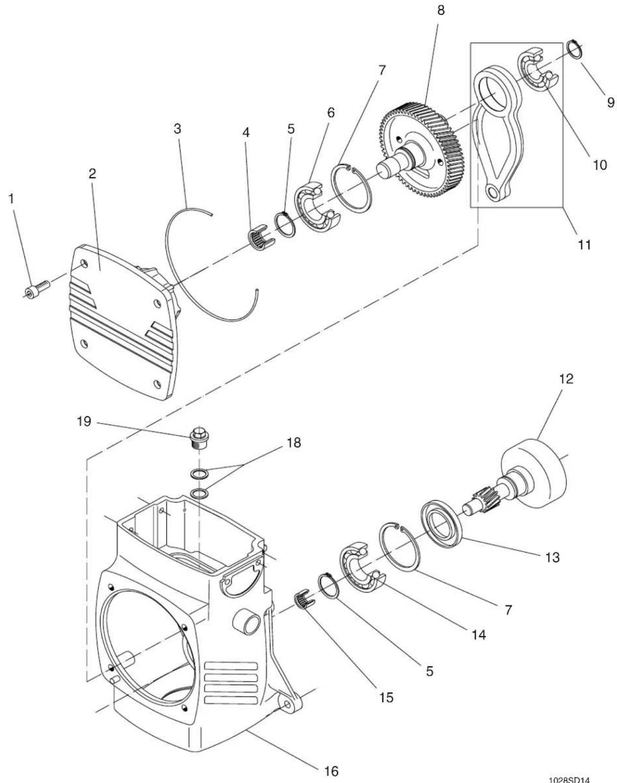
| Ref. | Part No. | Qty. | Description | Beschreibung | Descripción | Description |
| 1 001 | 11535 4 Screw M10x25 Schraube Tornillo Vis | |||||
| 2 009 | 4161 1 Cover-crankcase Deckel Tapa Couvercle | |||||
| 3 003 | 9026 1 O-Ring Anillo-O | Joint torique | ||||
| 4 | 0072061 | 1 | Bearing-needle | Nadellager | Rodamiento de agujas | Roulement à aiguilles |
| 5 | 2003022 | 2 | Ring, snap | Spengring | Anillo de sujeción | Anneau d'agrafe |
| 6 | 2003021 | 1 | Bearing-ball | Kugellager | Rodamiento de bolas | Roulement à billes |
| 7 | 2003023 | 2 | Retaining ring | Sicherungsring | Anillo de retención | Bague d'arrêt |
| 8 | 0095952 | 1 | Gear-crank assy. | Kurbeltrieb | Engranaje cigueñal | Commande à manivelle |
| 9 200 | 1041 1 Ring | Ring | Anillo | Anneau | ||
| 10 | 0045190 | 1 | Bearing-ball | Kugellager | Rodamiento de bolas | Roulement à billes |
| 11 | 0089591 | 1 | Connecting rod compl. | Pleuel kompl. | Biela compl. | Bielle compl. |
| 12 | 0095951 | 1 | Clutch drum | Fliehkraftglocke | Campana de embrague | Carter d'embrayage |
| 13 | 0039050 | 1 | Seal-shaft | Wellendichtring | Sello del eje | Bague d'étanchéité |
| 14 | 2003021 | 1 | Bearing-ball | Kugellager | Rodamiento de bolas | Roulement à billes |
| 15 | 0039020 | 1 | Bearing-needle roller | Nadellager | Rodamiento de agujas | Roulement à aiguilles |
| 16 | 0113857 | 1 | Crankcase | Kurbelgehäuse | Cárter | Carter |
| 18 | 0012083 | 2 | Seal-ring | Dichtungsring | Anillo sellador | Rondelle à étancher |
| 19 | 0096034 | 1 | Plug M20x1.5 | Schraubverschluß | Tapón roscado | Bouchon |
2.9 Spring cylinder / Federzylinder / Cilindro de resorte / Cylindre de ressort

| Ref. | Part No. | Qty. | Description | Beschreibung | Descripción | Description |
| 1 001 | 1543 14 Screw M8x20 Schraube Tornillo Vis | |||||
| 2 001 | 12397 7 Washer-lock Federring Disco de resorte Rondelle de ressort | |||||
| 3 | 0013971 | 1 | Sightglass with gasket | Ölschauglas mit Dichtung | Indicador de aceite con empaque | Indicateur avec joint |
| 0053829 | 1 | Gasket | Dichtung | Empaque | Joint | |
| 4 | 0039800 | 1 | Pipe-protective | Schutzrohr | Tubo de protección Joint | Tube de protection |
| 5 004 | 43204 1 Seal | Dichtung | Empaque | |||
| 6 | 0110350 | 1 | Ram | Führungskolben | Pistón | Piston |
| 7 | 0114080 | 1 | Spring cylinder | Federzylinder | Cilindro de resorte | Cylindre de ressort |
| 8 | 0012082 | 1 | Gasket | Dichtung | Empaque | Joint |
| 9 001 | 11050 1 Screw, M16x1.5 Schraube Tornillo Vis | |||||
| 10 | 0113843 | 1 | Set-springs | Federsatz | Juego de resortes | Jeu de ressorts |
| 12 003 | 44442 1 Bush-ing-impact, plastic Buchse Buje Douille | |||||
| 13 | 0039795 | 1 | Guide, percussion piston | Führung | Guía | Guide |
| 14 | 0083814 | 1 | Nut-lock | Sicherungsmutter | Contratuerca | Contre-écrou |
| 15 | 0034601 | 1 | Bushing | Buchse | Buje | Douille |
| 17 | 0039757 | 1 | Gasket-spring cylinder | Dichtung | Empaque | Joint |
| 18 | 0114844 | 1 | Cover-spring cylinder | Deckel | Tapa | Couvercle |
2.11 Labels / Aufkleber / Calcomania / Autocollants

1029SD33
| Ref. | Part No. | Qty. | Description | Beschreibung | Descripción | Description |
| 1 007 | 9687 1 Label | warning, spring Aufkleber-War | ung Calcomania- Autocollant- | Advertencia Avertissement | ||
| 2 011 | 15413 1 Label | sheet, hot Aufkleber-heisse replace guard | calcomania- Autocollant-surface | superficie caliente | brûlante | |
| 3 011 | 14609 1 Label-Wacker logo Aufkleber | er logo Aufkleber | Calcomania | Autocollant | ||
| 4 | 0114608 | 1 | Label-Wacker symbol | Aufkleber | Calcomania | Autocollant |
Part Numbers appearing in boldface type are recommended spare parts. This means that these parts are subject to wear under normal operating conditions and may require periodic service or replacement. It is recommended that these items be stocked to meet the expected service requirements of this model. Actual stocking quantities of these and other parts used in more extensive repairs will depend on the service practices of each customer.
[L1] Indicates a sealant or threadlocking compound to be used when assembling part. Refer to Sealant Chart at end of manual for description of sealants.
[T1] Indicates the correct torque value for assembling part. Refer to Torque Chart at end of manual for standard torque measurements.
1028SD20
| Ref. | Part No. | Qty. | Description | Beschreibung | Descripción | Description |
| 1 00 | 11457 1 Screw M8x25 Schraube Tornillo | Vis | ||||
| 2 10 | 05118 1 Washer Scheibe | Arandela Rondelle | ||||
| 3 | 0069863 | 1 | Clutch-centrifugal | Kupplung | Embrague | Embrayage |
| 0098466 | 2 | Lining | Belag | Estribo | Bande de garniture | |
| 0098467 | 4 | Spring-clutch | Feder | Resorte | Ressort | |
| 4 00 | 73665 2 Nut M8 | Mutter | Tuerca | Ecrou | ||
| 5 | 0011470 | 2 | Screw M6x20 | Schraube | Tornillo | Vis |
| 6 | 0058381 | 2 | Washer-lock | Federring | Disco de resorte | Rondelle de ressort |
| 7 | 0095870 | 1 | Muffler | Auspufftopf | Silenciador | Pot d'échappement |
| 8 | 0049991 | 1 | Plug M8x1 | Schraubverschluß | Tapón roscado | Bouchon |
| 9 | 0095856 | 1 | Guide-air | Führung | Guía | Guide |
| 10 00 | 12356 6 Screw M6x10 Schraube | Tornillo Vis | ||||
| 11 | 0104549 | 1 | Starter, cpl. | Starter | Arrancador | Démarreur |
| 12 | 0118381 | 1 | Engine-diesel cpl.(incl. 1-11, 13-19) | Diesel-Motor(inkl. 1-11, 13-19) | Motor Diesel(incl. 1-11, 13-19) | Moteur Diesel(incl. 1-11, 13-19) |
| 13 | 0010932 | 4 | Stud M10x30 | Gewindebolzen | Perno prisionero | Boulon |
| 14 | 0033356 | 2 | Nut-lock | Sicherungsmutter | Contratuerca | Contre-écrou |
| 15 01 | 03232 1 Guard-throttle linkage Schutz | Protector | Protecteur | |||
| 16 00 | 10622 2 Washer Scheibe | Arandela Rondelle | ||||
| 17 00 | 11340 2 Screw M8x35 Schraube | Tornillo Vis | ||||
| 18 | 0033198 | 1 | Washer-lock | Federring | Disco de resorte | Rondelle de ressort |
| 19 | 0098595 | 1 | Bellows-lever | Faltenbalg | Fuelle | Soufflet |
3.4 Starter Complete / Starter vollständig / Juego de Arrancador cpl. / Jeu de Démarreur cpl.

| Ref. | Part No. | Qty. | Description | Beschreibung | Descripción | Description |
| 1 0058553 1 Nut-lock Sicherungsmutter Contratuertauerca Contre-écrou | ||||||
| 2 | 0058381 | 1 | Washer-lock | Federring | Disco de resorte | Rondelle de ressort |
| 3 | 0047997 | 1 | Cover, starter rope | Deckel | Tapa | Couvercle |
| 4 | 0047998 | 1 | Ratchet -pawl | Ratsche | Trinquete | Cliquet |
| 5 | 0048062 | 1 | Washer | Scheibe | Arandela | Rondelle |
| 6 | 0103163 | 1 | Spring, return | Feder | Resorte | Ressort |
| 7 | 0065068 | 1 | Plate-wear, starter | Schleißplatte | Placa de desgaste | Plaque d'usure |
| 8 | 0044233 | 1 | Handle-rewind starter | Handgriff | Manija | Poignée |
| 9 | 0104548 | 1 | Rope, recoil starter | Seil | Cuerda | Corde |
| 10 | 0103286 | 1 | Housing-starter | Startergehäuse | Caja del arrancador | Carter de démarreur |
| 11 | 0102283 | 1 | Pulley | Scheibe | Polea | Poulie |
| 12 | 0048059 | 1 | Spring | Feder | Resorte | Ressort |
| 13 | 0033198 | 1 | Washer-lock | Federring | Disco de resorte | Rondelle de ressort |
| 14 | 0013552 | 1 | Screw M8x10 | Schraube | Tornillo | Vis |
| 15 | 0105056 | 1 | Shockmount | Puffer | Amortiguador | Silentbloc |
| 16 | 0104549 | 1 | Starter, cpl.(incl. 1-15) | Starter(inkl. 1-15) | Arrancador(incl. 1-15) | Démarreur(incl. 1-15) |
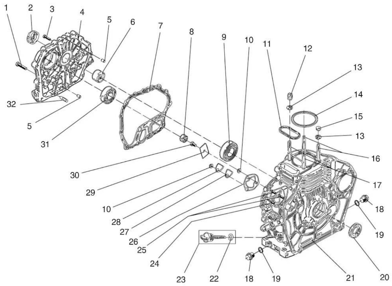
3.5 Crankcase / Kurbelgehäuse / Cárter / Carter
1028SD22
| Ref. | Part No. | Qty. | Description | Beschreibung | Descripción | Description |
| 1 001 | 1455 1 Screw M8x35 Schraube Tornillo Vis | |||||
| 2 | 0073620 | 1 | Seal-shaft | Wellendichtring | Sello del eje | Bague d'étanchéité |
| 3 001 | 1469 14 Screw M6x25 Schraube Tornillo Vis | |||||
| 4 | 0067956 | 1 | Cover-bearing | Halter | Soporte | Support |
| 5 | 0096704 | 2 | Pin-straight | Stift | Pasador | Goupille |
| 6 007 | 3619 1 Bearing-sleeve Lager | Rodamiento Roulement | ||||
| 7 | 0096707 | 1 | Gasket-housing | Dichtung | Empaque | Joint |
| 8 | 0073621 | 1 | Bearing-needle, roller | Nadellager | Rodamiento de agujas | Roulement à aiguilles |
| 9 200 | 1269 1 Bearing, ball Lager | Rodamiento Roulement | ||||
| 10 007 | 3617 3 Nut | Mutter | Tuerca | Ecrou | ||
| 11 | 0073603 | 1 | Ring-rubber seal | Ring | Anillo | Anneau |
| 12 007 | 3600 2 Nut | Mutter | Tuerca | Ecrou | ||
| 13 007 | 3601 4 Washer Scheibe Arandela Rondelle | |||||
| 14 | 0073602 | 1 | Gasket-cylinder head | Dichtung | Empaque | Joint |
| 0096724 | 1 | Set-gaskets | Dichtungssatz | Juego de juntas | Jeu de joints | |
| 15 007 | 3599 2 Nut | Mutter | Tuerca | Ecrou | ||
| 16 007 | 3598 2 Bolt | Bolzen | Perno | Boulon | ||
| 17 007 | 3597 2 Bolt | Bolzen | Perno | Boulon | ||
| 18 | 0011034 | 2 | Plug M16 | Schraubverschluß | Tapón roscado | Bouchon |
| 19 | 0012082 | 2 | Seal-ring | Dichtungsring | Anillo sellador | Rondelle à étancher |
| 20 | 0096715 | 1 | Seal-shaft | Wellendichtring | Sello del eje | Bague d'étanchéité |
| 21 | 0096716 | 1 | Crankcase | Kurbelgehäuse | Cárter | Carter |
| 22 | 0073609 | 1 | O-Ring | O-Ring | Anillo-O | Joint torique |
| 23 | 0096713 | 1 | Oil, dipstick (incl. 22) | Peilstab (inkl. 22) | Varilla indicadora(incl. 22) | Jauge d'huile(incl. 22) |
| 24 | 0013507 | 1 | Stud M6x18 | Gewindebolzen | Perno prisionero | Boulon |
| 25 | 0013508 | 2 | Bolt M6x22 | Bolzen | Perno | Boulon |
| 26 | 0073610 | 1 | Set-engine shims | Satz-Ausgleichscheiben | Juego de laminillas | Jeu de cales |
| 27 | 0073612 | 1 | Gasket | Dichtung | Empaque | Joint |
| 28 | 0073611 | 1 | Cover | Deckel | Tapa | Couvercle |
| 29 | 0073618 | 1 | Holder | Halter | Soporte | Attache |
| 30 001 | 2360 1 Screw M8x12 Schraube Tornillo Vis | |||||
| 31 002 | 20313 1 Bearing, ball Lager | Rodamiento Roulement | ||||
| 32 009 | 6706 1 Pipe | Rohr | Tubo | Tube | ||
3.6 Crankcase / Kurbelgehäuse / Cárter / Carter

1028SD23
| Ref. | Part No. | Qty. | Description | Beschreibung | Descripción | Description | |
| 1 | 0096725 | 1 | Piston assy. (incl. 2) | Kolben (inkl. 2) | Pistón (incl. 2) | Piston (incl. 2) | |
| 0087430 | 1 | Piston assy. .25mm (incl. 2) | Kolben (inkl. 2) | Pistón (incl. 2) | Piston (incl. 2) | ||
| 0087432 | 1 | Piston assy. .50mm (incl. 2) | Kolben (inkl. 2) | Pistón (incl. 2) | Piston (incl. 2) | ||
| 2 0073682 1 Set | - piston | Kolbenringsatz Juego de anillos rings | Jeu de segments | ||||
3.7 Governor lever / Regler / Gobernador / Régulateur

1028SD24
| Ref. | Part No. | Qty. | Description | Beschreibung | Descripción | Description |
| 1 0012357 3 Screw M6x12 Schraube Tornillo Vis | ||||||
| 2 0073694 1 Cover-engine oil pump Deckel Tapa | Couvercle | |||||
| 3 | 0073696 | 1 | O-Ring | O-Ring | Anillo-O | Joint torique |
| 4 | 0073698 | 1 | Pump-oil circulation | Pumpe | Bomba | Pompe |
| 5 | 0073648 | 1 | Pin, straight | Stift | Pasador | Goupille |
| 6 | 0073693 | 1 | O-Ring | O-Ring | Anillo-O | Joint torique |
| 7 | 0096745 | 1 | Filter-oil | Ölfilter | Filtro de aceite | Filtre d'huile |
| 8 0014663 1 Screw M6x16 Schraube Tornillo Vis | ||||||
| 9 | 0096746 | 1 | Governor cpl. | Regler | Gobernador | Régulateur |
| 10 | 0073703 | 1 | Washer | Scheibe | Arandela | Rondelle |
| 11 0073701 2 Bearing-needle roller Lager | Rodamiento Roulement | |||||
| 12 | 0073699 | 1 | Lever cpl., governor control (incl. 10, 11) | Hebel (inkl. 10, 11) | Palanca (incl. 10, 11) | Levier (incl. 10, 11) |
| 13 | 0073790 | 1 | Nut-lock M10 | Sicherungsmutter | Contratuerca | Contre-écrou |
| 14 | 0087374 | 1 | Seal-oil | Öldichtung | Empaque de aceite | Joint d'huile |
| 0087375 | 1 | Washer-thrust | Druckscheibe | Arandela de presión | Rondelle de facette | |
| 15 | 0073787 | 1 | Control | Betätigung | Gobierno | Commande |
| 16 | 0073783 | 1 | Bracket, cpl. | Konsole | Ménsula | Support |
| 17 0096753 1 Screw, adjusting Schraube Tornillo Vis | ||||||
| 18 | 0010880 | 1 | Nut-lock M6 | Sicherungsmutter | Contratuerca | Contre-écrou |
| 19 0013547 1 Screw, hex M4x8 Schraube Tornillo Vis | ||||||
| 20 | 0073780 | 1 | Handle | Handgriff | Manija | Poignée |
| 21 | 0096755 | 1 | Spring-torsion | Feder | Resorte | Ressort |
| 22 | 0096756 | 1 | Spring-tension | Zugfeder | Resorte de tracción | Ressort de traction |
| 23 | 0073781 | 1 | Spring-tension | Zugfeder | Resorte de tracción | Ressort de traction |
| 24 0012357 1 Screw M6x12 Schraube Tornillo Vis | ||||||
| 25 0037600 1 Screw M6x20 Schraube Tornillo Vis | ||||||
3.8 Cylinder head / Zylinderkopf / Culata del cilindro / Culasse de cylindre
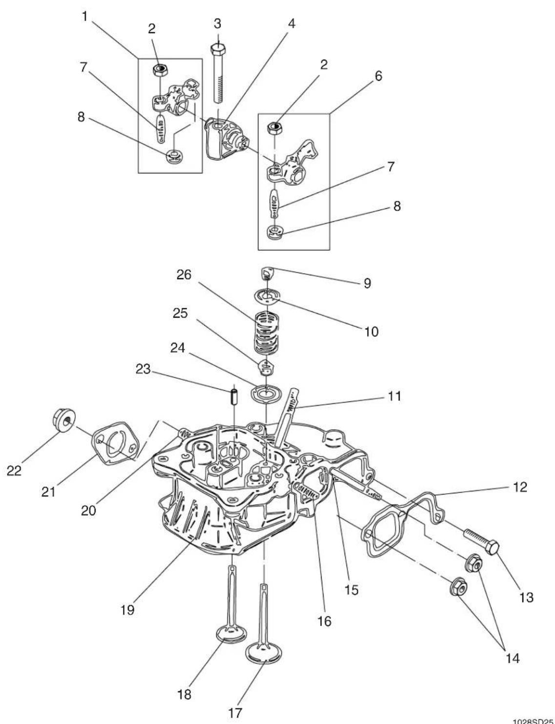
| Ref. | Part No. | Qty. | Description | Beschreibung | Descripción | Description |
| 1 0096762 1 Rocker arm outlet Kipphebel Balancín Culbuteur(incl. 2, 7, 8) (inkl. 2, 7, 8) (incl. 2, 7, 8) | ||||||
| 2 0010803 2 Nut, hex Mutter Tuerca Ecrou | ||||||
| 3 | 0011342 | 1 | Screw, hex M8x45 | Schraube | Tornillo | Vis |
| 4 | 0073629 | 1 | Holder-rocker arm | Kipphebelbock | Soporte de balancín | Support |
| 6 | 0096763 | 1 | Rocker arm inlet(incl. 2, 7, 8) (inkl. 2, 7, 8) (incl. 2, 7, 8) | Kipphebel | Balancín | Culbuteur |
| 7 | 0096764 | 2 | Control, adjusting screw | Betätigung | Gobierno | Commande |
| 8 0096765 2 Cap Kappe Tapa Couvercle | ||||||
| 9 | 0073628 | 2 | Set-valve cones | Ventilkonusatz | Juego de conos | Jeu de cônes |
| 10 0073627 2 Holder-valve springs Halter Soporte Attache | ||||||
| 11 | 0073636 | 2 | Bolt, stud M6x50 | Bolzen | Perno | Boulon |
| 12 0073651 1 Gasket Dichtung Empaque Joint | ||||||
| 13 | 0011469 | 1 | Screw, hex M6x25 | Schraube | Tornillo | Vis |
| 14 | 0095948 | 2 | Nut, hex M6 | Mutter | Tuerca | Ecrou |
| 15 | 0013512 | 1 | Bolt, stud M6x55 | Bolzen | Perno | Boulon |
| 16 | 0013507 | 1 | Bolt, stud M6x18 | Bolzen | Perno | Boulon |
| 17 | 0073624 | 1 | Valve-intake | Ventil | Válvula | Soupape |
| 18 | 0096772 | 1 | Valve-outlet | Ventil | Válvula | Soupape |
| 19 | 0073623 | 1 | Head-engine cylinder | Zylinderkopf | Culata del cilindro | Culasse de cylindre |
| 20 | 0020343 | 1 | Bolt, stud M8x18 | Bolzen | Perno | Boulon |
| 21 0073660 1 Gasket Dichtung Empaque Joint | ||||||
| 22 | 0073665 | 2 | Nut, hex M8 | Mutter | Tuerca | Ecrou |
| 23 0073648 1 Pin Stift Pasador Goupille | ||||||
| 24 | 0073634 | 2 | Washer | Scheibe | Arandela | Rondelle |
| 25 0073631 2 Seal-engine Dichtung Empaque Joint | ||||||
| 26 | 0073626 | 2 | Spring-engine valves | Feder | Resorte | Ressort |
3.9 Cylinder head / Zylinderkopf / Culata del cilindro / Culasse de cylindre

1028SD26
| Ref. | Part No. | Qty. | Description | Beschreibung | Descripción | Description |
| 1 002 003 | 10624 2 Washer Screw M6 | Scheibe Arandela Rondellex55 Schraube Tornillo Vis | ||||
| 11332 2 Screw M6 | ||||||
| 0096758 | 1 | Plug | Stopfen | Tapón | Bouchon | |
| 4 | 0073644 | 1 | Cover-assy., cylinder head | Deckel | Tapa | Couvercle |
| 5 | 0073643 | 1 | Gasket | Dichtung | Empaque | Joint |
3.10 Injection valve / Einspritzventil / Válvula inyectora / Soupape d'injection

1028SD27
| Ref. | Part No. | Qty. | Description | Beschreibung | Descripción | Description |
| 1 | 0096776 | 1 | Pipe-pressure | Druckrohr | Tubo de presión | Tube de pression |
| 2 0096777 1 Pump, injection Pumpe Bomba Pompe | ||||||
| 3 0073617 2 Nut M6 Mutter Tuerca Ecrou | ||||||
| 4 | 0073642 | 1 | Holder | Halter | Soporte | Attache |
| 5 | 0073722 | 1 | Valve, injection cpl. | Ventil | Válvula | Soupape |
| 6 | 0073633 | 1 | Spacer-washer | Abstandsscheibe | Arandela espaciadora | Rondelle d'écartement |
| 7 | 0073632 | 1 | Gasket | Dichtung | Empaque | Joint |
1028SD28
| Ref. | Part No. | Qty. | Description | Beschreibung | Descripción | Description |
| 1 001 | 12357 1 Screw M6x | 12 Schraube Tornillo Vis | ||||
| 2 | 0096786 | 1 | Guide-air | Führung | Guía | Guide |
| 3 | 0073760 | 1 | Molding-rubber strip | Profilgummi | Moldura | Garniture |
| 4 | 0109334 | 1 | Cover-fan | Deckel | Tapa | Couvercle |
| 5 007 | 3778 1 Pulley | Scheibe | Polea | Poulie | ||
| 6 001 | 12357 3 Screw M6x | 12 Schraube Tornillo Vis | ||||
| 7 001 | 1469 4 Screw M6x | 25 Schraube Tornillo Vis | ||||
| 8 001 | 10373 4 Washer | Scheibe | Arandela Rondelle | |||
| 9 | 0073759 | 4 | Ring-collar | Ring | Anillo | Anneau |
| 10 | 0073758 | 4 | Grommet .390 I.D. | Tülle | Ojal | Passe-fil |
| Part No. Page(s) Part No. Page(s) Part No. Page(s) | ||
| 0010366 2-7 | 0037600 3-13 | 0073644 3-16 |
| 0010367 2-5, 2-6, 2-7 | 0039020 2-11 | 0073648 3-15 |
| 0010368 2-5 | 0039026 2-11 | 0073651 3-15 |
| 0010373 3-18 | 0039050 2-11 | 0073660 3-15 |
| 0010622 2-5, 3-5 | 0039757 2-13 | 0073665 2-6, 3-15 |
| 0010624 2-5, 3-16 | 0039785 2-8 | 0073671 3-11 |
| 0010644 2-8 | 0039795 2-13 | 0073672 3-11 |
| 0010803 3-15 | 0039800 2-13 | 0073675 3-11 |
| 0010880 3-13 | 0043204 2-13 | 0073678 3-11 |
| 0010932 3-5 | 0044233 3-7 | 0073682 3-11 |
| 0011034 3-9 | 0045190 2-11 | 0073689 3-11 |
| 0011050 2-13 | 0047987 2-7 | 0073693 3-13 |
| 0011157 2-7 | 0047997 3-7 | 0073694 3-13 |
| 0011192 2-7 | 0047998 3-7 | 0073696 3-13 |
| 0011193 2-7 | 0048059 3-7 | 0073698 3-13 |
| 0011194 2-7 | 0048062 3-7 | 0073699 3-13 |
| 0011332 3-16 | 0049991 3-5 | 0073701 3-13 |
| 0011340 3-5 | 0052028 3-11 | 0073703 3-13 |
| 0011341 2-5 | 0053829 2-13 | 0073722 3-17 |
| 0011342 3-15 | 0058381 2-5, 3-5, 3-7 | 0073751 2-9 |
| 0011421 2-6 | 0058498 2-5 | 0073758 3-18 |
| 0011455 3-9 | 0058553 3-7 | 0073759 3-18 |
| 0011457 3-5 | 0065068 3-7 | 0073760 3-18 |
| 0011469 3-9, 3-15, 3-18 | 0067956 3-9 | 0073778 3-18 |
| 0011470 3-5 | 0069863 3-5 | 0073780 3-13 |
| 0011533 2-8 | 0072061 2-11 | 0073781 3-13 |
| 0011535 2-11 | 0072069 2-7 | 0073783 3-13 |
| 0011543 2-5, 2-6, 2-13 | 0073597 3-9 | 0073787 3-13 |
| 0011551 2-5 | 0073598 3-9 | 0073790 3-13 |
| 0011553 2-5 | 0073599 3-9 | 0074552 2-5 |
| 0012082 2-13, 3-9 | 0073600 3-9 | 0078844 2-5 |
| 0012083 2-11 | 0073602 3-9 | 0079687 2-14 |
| 0012356 3-5 | 0073603 3-9 | 0083814 2-13 |
| 0012357 3-13, 3-18 | 0073609 3-9 | 0087023 2-5 |
| 0012360 2-5, 2-6 | 0073610 3-9 | 0087374 3-13 |
| 0012397 2-13 | 0073611 3-9 | 0087375 3-13 |
| 0013507 3-9, 3-15 | 0073612 3-9 | 0087430 3-11 |
| 0013508 3-9 | 0073617 2-9, 3-17 | 0087431 3-11 |
| 0013512 3-15 | 0073618 3-9 | 0087432 3-11 |
| 0013547 3-13 | 0073619 3-9 | 0087433 3-11 |
| 0013552 3-7 | 0073620 3-9 | 0087434 3-11 |
| 0013971 2-13 | 0073621 3-9 | 0087435 3-11 |
| 0014663 3-13 | 0073623 3-15 | 0088842 2-8 |
| 0016836 2-9 | 0073624 3-15 | 0089591 2-11 |
| 0020313 3-9 | 0073626 3-15 | 0094161 2-11 |
| 0020343 3-15 | 0073627 3-15 | 0095254 2-6 |
| 0023619 2-5 | 0073628 3-15 | 0095856 3-5 |
| 0031565 2-6 | 0073629 3-15 | 0095870 3-5 |
| 0031880 2-8 | 0073631 3-15 | 0095948 3-9, 3-15 |
| 0033198 2-5, 3-5, 3-7 | 0073632 3-17 | 0095949 2-9 |
| 0033356 3-5 | 0073633 3-17 | 0095950 2-9 |
| 0034394 3-15 | 0073634 3-15 | 0095951 2-11 |
| 0034442 2-13 | 0073642 3-17 | 0095952 2-11 |
| 0034601 2-13 | 0073643 3-16 | 0096034 2-11 |
| 0096087 2-5 | 0110350 2-13 | |
| 0096677 3-5 | 0110586 2-9 | |
| 0096704 3-9 | 0111461 2-6 | |
| 0096706 3-9 | 0111482 2-9 | |
| 0096707 3-9 | 0111765 2-5 | |
| 0096713 3-9 | 0112077 2-5 | |
| 0096715 3-9 | 0112299 2-6 | |
| 0096716 3-9 | 0113843 2-13 | |
| 0096724 3-9 | 0113857 2-11 | |
| 0096725 3-11 | 0114080 2-13 | |
| 0096727 3-11 | 0114608 2-14 | |
| 0096728 3-11 | 0114609 2-14 | |
| 0096730 3-11 | 0114798 2-5 | |
| 0096731 3-11 | 0114844 2-13 | |
| 0096732 3-11 | 0115410 2-6 | |
| 0096733 3-11 | 0115413 2-14 | |
| 0096736 3-11 | 0118381 2-5, 3-5 | |
| 0096737 3-11 | 0123600 3-9 | |
| 0096743 3-13 | 0736601 3-9 | |
| 0096745 3-13 | 1005118 2-7, 3-5 | |
| 0096746 3-13 | 1006882 2-8 | |
| 0096753 3-13 | 1006925 2-8 | |
| 0096755 3-13 | 2001041 2-11 | |
| 0096756 3-13 | 2001269 3-9 | |
| 0096758 3-16 | 2003021 2-11 | |
| 0096762 3-15 | 2003022 2-11 | |
| 0096763 3-15 | 2003023 2-11 | |
| 0096764 3-15 | 2003749 3-11 | |
| 0096765 3-15 | 2006976 2-8 | |
| 0096772 3-15 | ||
| 0096776 3-17 | ||
| 0096777 3-17 | ||
| 0096779 2-9 | ||
| 0096786 3-18 | ||
| 0098466 3-5 | ||
| 0098467 3-5 | ||
| 0098595 3-5 | ||
| 0102274 2-6 | ||
| 0102282 3-7 | ||
| 0103163 3-7 | ||
| 0103232 3-5 | ||
| 0103286 3-7 | ||
| 0104093 2-9 | ||
| 0104543 2-5 | ||
| 0104548 3-7 | ||
| 0104549 3-5, 3-7 | ||
| 0105056 2-5, 3-7 | ||
| 0105194 2-5 | ||
| 0106103 2-5 | ||
| 0107171 2-5 | ||
| 0107462 2-5 | ||
| 0108200 2-5 | ||
| 0108414 2-5 | ||
| 0109334 3-18 |
Use Of Threadlockers and Sealants
Threadlocking adhesives and sealants are specified throughout this manual and should be used where indicated. Threadlocking compounds normally break down at temperatures above 350^ F ( 175^ C). If a screw or bolt is hard to remove, heat it using a small propane torch to break down sealant. When applying sealants, follow instructions on container. The sealants listed below are recommended for use on WACKER equipment.
| TYPE( ) = Europe COLOR USAGE PART NO. - SIZE | |||
| Loctite 222 Purple Low strength, for Hernon 420 Hand tool removable.Omnifit 1150 (50M) Temp. range, -65 to 300 degrees F (-54 to 149 degrees C) | |||
| Loctite 243 Blue Medium strength, for Hernon 423 Hand tool removable. 17380 - 50 mlOmnifit 1350 (100M) Temp. range, -65 to 300 degrees F (-54 to 149 degrees C) | |||
| Loctite 271 / 277Hernon 427 Heat parts before disasOmnifit 1550 (220M) | Red | High strength, for all threads up to 1" (25 mm).Assembly. 26685 - 10 mlTemp. range, -65 to 300 degrees F (-54 to 149 degrees C) | 29312 - .5 ml73285 - 50 ml |
| Loctite 290Hernon 431 and for sealing weld porOmnifit 1710 (230LL) | Green | Medium to high strength, for locking preassembled threads porosity (wicking). 25316 - 10 mlGaps up to 0.005" (0.13 mm)Temp. range, -65 to 300 degrees F (-54 to 149 degrees C) | 28824 - .5 ml |
| Loctite 609Hernon 822 of shafts,Omnifit 1730 (230L) | Green | Medium strength retaining compound for slip or press fitbearings, gears, pulleys, etc.Gaps up to 0.005" (0.13 mm)Temp. range, -65 to 300 degrees F (-54 to 149 degrees C) | 29314 - .5 ml |
| Loctite 545 BrownHernon 947 Temp. range, -65 to 300 degrees F (-54 to 149 degrees C)Omnifit 1150 (50M) | Hydraulic | sealant 79356 - 50 ml | |
| Loctite 592Hernon 920 Temp. range, -65 to 300 degrees F (-54 to 149 degrees C)Omnifit 790 | White | Pipe sealant with Teflon for moderate pressures. degrees F (-54 to 149 degrees C) 73289 - 50 ml | 26695 - 6 ml |
| Loctite 515 Purple Form-in-place gap Hernon 910 Fills gaps up to 0.05" (1.3 mm)Omnifit 10 | up to 0.05" (1.3 mm) | 70735 - 50 mlTemp. range, -65 to 300 degrees F (-54 to 149 degrees C) | |
| Loctite 496 ClearHernon 110Omnifit Sicomet 7000 | Instant adhesive for bonding rubber, metal and plastics;general purpose.For gaps up to 0.006" (0.15 mm)Read caution instructions before using.Temp. range, -65 to 180 degrees F (-54 to 82 degrees C) | 52676 - 1 oz. | |
| Loctite Primer THernon Primer 10Omnifit VC Activator | Aerosol Spray | Fast curing primer for threadlocking, retaining and sealing compounds. Must be used with stainless steel hardware. Recommended for use with gasket sealants. | 2006124 - 6 oz. |
Metric Fasteners (DIN)
| TORQUE VALUES (Based on Bolt Size and Hardness) | WRENCH SIZE | |||||||||
 |  |  |  |  |  |  |  |  | ||
| Size Ft.L | b. Nm Ft. | Lb. Nm Ft. | Lbs. Nm | Inch Metric | Inch Metric | |||||
| M3 | *11 | 1.2 | *14 | 1.6 | *19 | 2.1 | 7/32 | 5.5 | - | 2.5 |
| M4 | *26 | 2.9 | *36 | 4.1 | *43 | 4.9 | 9/32 | 7 | - | 3 |
| M5 | *53 | 6.0 | 6 | 8.5 | 7 | 10 | 5/16 | 8 | - | 4 |
| M6 | 7 | 10 | 10 | 14 | 13 | 17 | - | 10 | - | 5 |
| M8 | 18 | 25 | 26 | 35 | 30 | 41 | 1/2 | 13 | - | 6 |
| M10 | 36 | 49 | 51 | 69 | 61 | 83 | 11/16 | 17 | - | 8 |
| M12 | 63 | 86 | 88 | 120 | 107 | 145 | 3/4 | 19 | - | 10 |
| M14 | 99 | 135 | 140 | 190 | 169 | 230 | 7/8 | 22 | - | 12 |
| M16 | 155 | 210 | 217 | 295 | 262 | 355 | 15/16 | 24 | - | 14 |
| M18 | 214 | 290 | 298 | 405 | 357 | 485 | 1-1/16 | 27 | - | 14 |
| M20 | 302 | 410 | 427 | 580 | 508 | 690 | 1-1/4 | 30 | - | 17 |
Inch Fasteners (SAE)
| SAE 5 | SAE 8 | |||||||||
| Size Ft.L | b. Nm Ft. | Lb. Nm Ft. | Lbs. Nm | Inch Metric | Inch Metric | |||||
| No.4 *6 0 | 7 *14 1.0 | *12 1.4 1/4 | 5.5 3/32 | - | ||||||
| No.6 | *12 | 1.4 | *17 | 1.9 | *21 | 2.4 | 5/16 | 8 | 7/64 | - |
| No.8 | *22 | 2.5 | *31 | 3.5 | *42 | 4.7 | 11/32 | 9 | 9/64 | - |
| No.10 | *32 | 3.6 | *45 | 5.1 | *60 | 6.8 | 3/8 | - | 5/32 | - |
| 1/4 | 6 | 8.1 | 9 | 12 | 12 | 16 | 7/16 | - | 3/32 | - |
| 5/16 | 13 | 18 | 19 | 26 | 24 | 33 | 1/2 | 13 | 1/4 | - |
| 3/8 | 23 | 31 | 33 | 45 | 43 | 58 | 9/16 | - | 5/16 | - |
| 7/16 | 37 | 50 | 52 | 71 | 69 | 94 | 5/8 | 16 | 3/8 | - |
| 1/2 | 57 | 77 | 80 | 109 | 105 | 142 | 3/4 | 19 | 3/8 | - |
| 9/16 | 82 | 111 | 115 | 156 | 158 | 214 | 13/16 | - | - | - |
| 5/8 | 112 | 152 | 159 | 216 | 195 | 265 | 15/16 | 24 | 1/2 | - |
| 3/4 | 200 | 271 | 282 | 383 | 353 | 479 | 1-1/8 | - | 5/8 | - |
EC - CONFORMITY CERTIFICATE
File certificate carefully
N92 W15000 Anthony Avenue Menomonee Falls, Wisconsin
53052-9007 USA (262) 255-0500 Fax (262) 255-0550
QDS720non epa

UNITED KINGDOM
| LONDON | LEA ROADWALTHAM CROSS, HERTS EN9 1AW | Tel. (44)(01992) 707200 |
| Washington | Washington/Tyne N37 1LH | Tel. (0191) 4 16 63 92 |
| Warrington | Winwick Quay, Warrington WA2 8RE | Tel. (01925) 57 39 55 |
| Worksop | Worksop S81 7BE | Tel. (01909) 48 45 06 |
| Redditch | Washford, Redditch B98 0DQ | Tel. (01527) 2 45 56 |
| Pontypool | Pontypool, Gwent NP4 6PD | Tel. (01495) 75 05 95 |
| Ashford | Ashford, Kent TN23 2NF | Tel. (01233) 64 52 27 |
| Exeter | Clyst, Honiton, Exeter EX5 2LG | Tel. (01392) 6 97 71 |
| Hungerford | Hungerford R617 OYX | Tel. (01488) 68 14 28 |
| Lanarks | Bellshill, Lanarks ML4 3NN | Tel. (01698) 84 58 15 |
ÖSTERREICH
| 1110 WIEN | SCHEMMERLSTR.82 | Tel. (43) 01-7671515 |
| 4050 Traun | Wiener Bundesstr. 147 | Tel. 07229-73739 |
| 9020 Klagenfurt | Wiegelegasse 18 Tel. 0463-262716 | |
| 8054 Graz-Strassgang | Kärntner Str. 512 | Tel. 0316-281690 |
| 6122 Fritzens | Innstr. 11 | Tel. 05224-51351 |
| 5300 Hallwang b. Sbg. | Wiener Bundesstr. 17 | Tel. 0662-661741 |
| 3106 St. Pölten | Hnilickastr. 9 | Tel. 02742-73170 |
Tel. (52-8) 331-12-85
Tel. 51-51-87
Tel. (47) 11-34-35
Tel. (29) 35-10-44
ARGENTINA
BUENOS AIRES 1611
Unit 2, 6-8 Pendrey Court
Unit P, 69-73 Hector Street
14 Vore Street
Tel. (61) 03-95474033
Tel. 07-32089577
Tel. 09-4452911
Tel. 02-7480366
JAPAN
OHTA-KU, TOYKO 144
Hirano-ku, Osaka-shi
Sendai-shi
Fukuoka-shi
2-CHOME 18-1, MINAMI-KAMATA
Miyake Nishi, 4-Chome
Tachimachi 1-7-21
Sannoh 1-7-1, Hakata-ku
Tel. (81) 03-37329201/5
Tel. 0723 30-0571
Tel. 022 284-8032
Tel. 092 451-1083
MALAYSIA
46150 PETALING JAYA
Selangor Darul Ehsan
- JALAN PJS 11/22
Bandar Sunway
Tel.(03)7984770
NEW ZEALAND
WIRI-AUCKLAND
4A Ponui Place
Mt. Wellington, Auckland
Tel. (04) (09) 270 3784
SINGAPORE
JURONG TOWN SINGAPORE 2263
NO. 23, Tuas Ave. 18
Tel (65) 861-0446
THAILAND
BANGKOK 10250
22/197 Pattanakarn Rd.
Soi Mooban Panya
Tel (66) 2-319-3821
SOUTH AFRICA
JOHANNESBURG
Durban
Capetown
1031 KATROL AVE., ROBERTVILLE X10
Roodepoort / P.O. Box 2163, Florida 1710, Gauteng.
10 Kinsman Rd. P.O. Box 420, New Germany 3620
Cor. Beatrix & Carel, Marincowitz St
P.O. Box 398, Brackenfell 7560 Tel. Cpt(021) 981-2197
Tel H/O Jhb(011) 672-0847
Tel. Dbn(031) 702-3337
CHINA
HONG KONG
Unit 611-612, 6/F Sunley Centre
9 Wing Yin Street
Kwai Chung, New Territories
Tel. (052) 24000013

0700
- ASSE-MOLLEM 1730 ASSE-MOCEM
- Safety Information
- DANGER
- WARNING
- CAUTION
- Operating Safety
- ! WARNING
- Operator Safety while using Internal Combustion Engines
- ! DANGER
- Service Safety
- Sound Measurements
- Vibration Measurements
- Technical Data
- Safety & Informational Labels
- Operating Labels
- Dimensions
- Description
- Applications
- Description of function
- Recommendations on compaction
- Soil conditions:
- Transportation
- 1A
- Recommended Fuel
- Before Starting
- To Start
- Operation
- To Stop
- Proper Compaction
- Periodic Maintenance Schedule
- Servicing Air Cleaner
- Lubrication
- Engine oil
- Check oil level:
- Oil change:
- Oil filter:
- Ramming system
- Shoe Hardware
- Long-Term Storage
- Inhaltsverzeichnis
- Abstellen
- 13" Ramming shoe / 330mm Stampfeinsatz / Placa de pisón 330mm / Sabot de frappe 330mm
- Ramming system / Stampfsystem / Sistema apisonador / Système du pilon
- Labels / Aufkleber / Calcomania / Autocollants
- Crankcase / Kurbelgehäuse / Cárter / Carter
- Governor lever / Regler / Gobernador / Régulateur
- Cylinder head / Zylinderkopf / Culata del cilindro / Culasse de cylindre
- Cylinder head / Zylinderkopf / Culata del cilindro / Culasse de cylindre
- Injection valve / Einspritzventil / Válvula inyectora / Soupape d'injection
- Use Of Threadlockers and Sealants
- ARGENTINA
- JAPAN
- MALAYSIA
- NEW ZEALAND
- SINGAPORE
- THAILAND
- SOUTH AFRICA
- CHINA
Brand : Wacker Neuson
Model : DS720
Category : Rammer