VP 1135A - Vibratory plate Wacker Neuson - Free user manual and instructions
Find the device manual for free VP 1135A Wacker Neuson in PDF.


| Product Type | Vibratory Plate |
| Brand | Wacker Neuson |
| Model | VP 1135A |
| Engine Type | 4-stroke gasoline, air-cooled |
| Engine Displacement | 212 cc |
| Centrifugal Force | 11.3 kN |
| Operating Weight | 95 kg (209 lbs) |
| Plate Size (L x W) | 560 x 400 mm (22 x 15.7 in) |
| Vibration Frequency | 6,000 vpm |
| Travel Speed | Up to 25 m/min (82 ft/min) |
| Fuel Tank Capacity | 3.6 L (0.95 US gal) |
| Water Tank Capacity | 10 L (2.64 US gal) |
| Starting System | Recoil start (manual) |
| Max Gradeability | 30% |
| Engine Oil Type | SAE 10W-30 or 15W-40 (API SJ or higher) |
| Oil Capacity | 0.6 L |
| Spark Plug Gap | 0.75 mm (0.030 in) |
| Safety Features | Deadman's handle, vibration-isolated handle, protective frame |
| Transport Weight (with protection frame) | 110 kg (242 lbs) |
| Sound Power Level (LWA) | 105 dB(A) |
Frequently Asked Questions - VP 1135A Wacker Neuson
User questions about VP 1135A Wacker Neuson
0 question about this device. Answer the ones you know or ask your own.
Ask a new question about this device
Download the instructions for your Vibratory plate in PDF format for free! Find your manual VP 1135A - Wacker Neuson and take your electronic device back in hand. On this page are published all the documents necessary for the use of your device. VP 1135A by Wacker Neuson.
USER MANUAL VP 1135A Wacker Neuson
5000191669 05 0311

| Copyright notice | © Copyright 2011 by Wacker Neuson Corporation. All rights, including copying and distribution rights, are reserved. This publication may be photocopied by the original purchaser of the machine. Any other type of reproduction is prohibited without express written permission from Wacker Neuson Corporation. Any type of reproduction or distribution not authorized by Wacker Neuson Corporation represents an infringement of valid copyrights. Violators will be prosecuted. |
| Trademarks | All trademarks referenced in this manual are the property of their respective owners. |
| Manufacturer | Wacker Neuson Manila Incorporated Lot 2,Blk 1 Phase , PEZA Drive, First Cavite Industrial Estate, Brgy. Langkaan Dasmariñas, Cavite, Philippines Tel: +63-(0)2-580-7136 Fax: +63-(0)2-580-712 www.wackerneuson.com |
| Translated instructions | This Operator's Manual presents a translation of the original instructions. The original language of this Operator's Manual is American English. |
AP 1135A Table of Contents
Foreword 3
1. Emission System Control Information 4
2. Safety Information 5
2.1 Laws Pertaining to Spark Arresters 5
2.2 Operating Safety 6
2.3 Operator Safety while using Internal Combustion Engines 7
2.4 Service Safety 8
2.5 Label Locations 9
2.6 Warning and Informational Labels 10
3. Technical Data 12
3.1 Engine Data 12
3.2 Machine Data 13
3.3 Sound and Vibration Measurements 13
3.4 Dimensions 14
4. Operation 15
4.1 Recommended Fuel 15
4.2 Application 15
4.3 Before Starting 15
4.4 To Start 16
4.5 To Stop 16
4.6 Operation 17
Table of Contents AP 1135A
5. Maintenance 18
5.1 Periodic Maintenance Schedule 18
5.2 Spark Plug 20
5.3 Air Cleaner 21
5.4 Engine Oil 22
5.5 Adjusting Engine Speed 22
5.6 Carburetor Adjustment 23
5.7 Cleaning Sediment Cup 23
5.8 Drive Belt 24
5.9 Exciter Lubrication 25
5.10 Cleaning the Plate 25
5.11 Lifting Machine 26
5.12 Transporting Machine 27
5.13 Storage 27
5.14 Troubleshooting 28
CALIFORNIA
Proposition 65 Warning:

Engine exhaust, some of its constituents, and certain vehicle components, contain or emit chemicals known to the State of California to cause cancer and birth defects or other reproductive harm.
Foreword
This manual provides information and procedures to safely operate and maintain this Wacker Neuson model. For your own safety and protection from injury, carefully read, understand and observe the safety instructions described in this manual.
Keep this manual or a copy of it with the machine. If you lose this manual or need an additional copy, please contact Wacker Neuson Corporation. This machine is built with user safety in mind; however, it can present hazards if improperly operated and serviced. Follow operating instructions carefully! If you have questions about operating or servicing this equipment, please contact Wacker Neuson Corporation.
The information contained in this manual was based on machines in production at the time of publication. Wacker Neuson Corporation reserves the right to change any portion of this information without notice.
All rights, especially copying and distribution rights, are reserved.
Copyright 2011 by Wacker Neuson Corporation.
No part of this publication may be reproduced in any form or by any means, electronic or mechanical, including photocopying, without express written permission from Wacker Neuson Corporation.
Any type of reproduction or distribution not authorized by Wacker Neuson Corporation represents an infringement of valid copyrights and will be prosecuted. We expressly reserve the right to make technical modifications, even without due notice, which aim at improving our machines or their safety standards.
Emission Control System Information
1 Emission Control Systems Information and Warranty
The Emission Control Warranty and associated information is valid only for the U.S.A., its territories, and Canada.
1.1 Emission Control Systems Warranty Statement
See the supplied engine owner's manual for the applicable exhaust and evaporative emission warranty statement.
AP 1135A Safety Information
2. Safety Information
This manual contains DANGER, WARNING, CAUTION, NOTICE, and NOTE signal words which must be followed to reduce the possibility of personal injury, damage to the equipment, or improper service.

This is the safety alert symbol. It is used to alert you to potential personal injury hazards. Obey all safety messages that follow this symbol to avoid possible injury or death.

DANGER indicates a hazardous situation which, if not avoided, will result in death or serious injury.

WARNING indicates a hazardous situation which, if not avoided, could result in death or serious injury.

CAUTION indicates a hazardous situation which, if not avoided, could result in minor or moderate injury.
NOTICE: Used without the safety alert symbol, NOTICE indicates a situation which, if not avoided, could result in property damage.
Note: Contains additional information important to a procedure.
2.1 Laws Pertaining to Spark Arresters
Notice: State Health Safety Codes and Public Resources Codes specify that in certain locations spark arresters be used on internal combustion engines that use hydrocarbon fuels. A spark arrester is a device designed to prevent accidental discharge of sparks or flames from the engine exhaust. Spark arresters are qualified and rated by the United States Forest Service for this purpose.
In order to comply with local laws regarding spark arresters, consult the engine distributor or the local Health and Safety Administrator.
2.2 Operating Safety
Safety Information AP 1135A

Familiarity and proper training are required for the safe operation of the machine. Machines operated improperly or by untrained personnel can be hazardous. Read the operating instructions contained in this manual and the engine manual, and familiarize yourself with the location and proper use of all controls. Inexperienced operators should receive instruction from someone familiar with the machine before being allowed to operate it.
2.2.1 Do not allow anyone to operate this equipment without proper training. People operating this equipment must be familiar with the risks and hazards associated with it.
2.2.2 Do not touch the engine or muffler while the engine is on or immediately after it has been turned off. These areas get hot and may cause burns.
2.2.3 Do not use accessories or attachments that are not recommended by Wacker Neuson. Damage to equipment and injury to the user may result.
2.2.4 NEVER operate the machine with the beltguard missing. Exposed drive belt and pulleys create potentially dangerous hazards that can cause serious injuries.
2.2.5 Never leave the machine running unattended.
2.2.6 Be sure operator is familiar with proper safety precautions and operation techniques before using machine.
2.2.7 Always wear protective clothing appropriate to the job site when operating the machine.
2.2.8 Wear hearing protection when operating equipment.
2.2.9 Close fuel valve on engines equipped with one when machine is not being operated.
2.2.10 Store the machine properly when it is not being used. The machine should be stored in a clean, dry location out of the reach of children.
2.2.11 Always operate machine with all safety devices and guards in place and in working order. Do not modify or defeat safety devices. Do not operate machine if any safety devices or guards are missing or inoperative.
2.2.12 Read, understand, and follow procedures in the Operator's Manual before attempting to operate the machine.
AP 1135A Safety Information
2.3 Operator Safety while using Internal Combustion Engines

Internal combustion engines present special hazards during operation and fueling. Read and follow the warning instructions in the engine owner's manual and the safety guidelines below. Failure to follow the warnings and safety standards could result in severe injury or death.
2.3.1
DO NOT run the machine indoors or in an enclosed area such as a deep trench unless adequate ventilation, through such items as exhaust fans or hoses, is provided. Exhaust gas from the engine contains poisonous carbon monoxide gas; exposure to carbon monoxide can cause loss of consciousness and may lead to death.
2.3.2 Do not smoke while operating the machine.
2.3.3 Do not smoke when refueling the engine.
2.3.4 Do not refuel a hot or running engine.
2.3.5 Do not refuel the engine near an open flame.
2.3.6 Do not spill fuel when refueling the engine.
2.3.7 Do not run the engine near open flames.
2.3.8 Refill the fuel tank in a well-ventilated area.
2.3.9 Replace the fuel tank cap after refueling.
2.3.10 ALWAYS check the fuel lines and the fuel tank for leaks and cracks before starting the engine. Do not run the machine if fuel leaks are present or the fuel lines are loose.
Safety Information AP 1135A
2.4 Service Safety

A poorly maintained machine can become a safety hazard! In order for the machine to operate safely and properly over a long period of time, periodic maintenance and occasional repairs are necessary.
2.4.1 Do not attempt to clean or service the machine while it is running. Rotating parts can cause severe injury.
2.4.2 Do not crank a flooded engine with the spark plug removed on gasoline-powered engines. Fuel trapped in the cylinder will squirt out the spark plug opening.
2.4.3 Do not test for spark on gasoline-powered engines if the engine is flooded or the smell of gasoline is present. A stray spark could ignite the fumes.
2.4.4 Do not use gasoline or other types of fuels or flammable solvents to clean parts, especially in enclosed areas. Fumes from fuels and solvents can become explosive.
2.4.5 Keep the area around the muffler free of debris such as leaves, paper, cartons, etc. A hot muffler could ignite the debris and start a fire.
2.4.6 Replace worn or damaged components with spare parts designed and recommended by Wacker Neuson Corporation.
2.4.7 Disconnect the spark plug on machines equipped with gasoline engines, before servicing, to avoid accidental start-up.
2.4.8 Keep the machine clean and labels legible. Replace all missing and hard-to-read labels. Labels provide important operating instructions and warn of dangers and hazards.
AP 1135A Safety Information
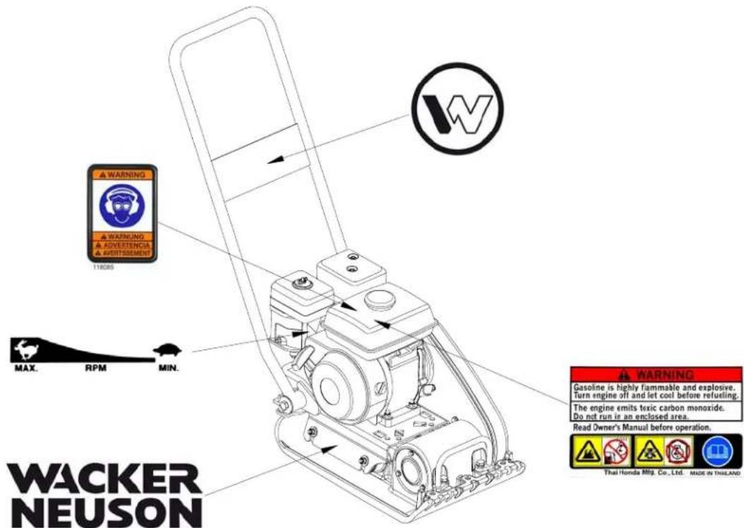
2.5 Label Locations

Safety Information AP 1135A
2.6 Warning and Informational Labels
Wacker Neuson machines use international pictorial labels where needed. These labels are described below.
| Label Meaning | |
 | WARNING!Hot surface! |
 | Guaranteed sound power level in dB(A). |
 | WARNING!Hand injury if caught in moving belt.Always replace beltguard. |
 | CAUTION!Read and understand the supplied Operator's Manual before operating this machine. Failure to do so increases the risk of injury to yourself and others. |
 118085 118085 | WARNING!Always wear hearing and eye protection when operating this machine. |
 | Throttle control lever:Turtle = Idle or SlowRabbit = Full or Fast |
AP 1135A Safety Information
| Label Meaning | |
 | DANGER! Engines emit carbon monoxide; operate only in well-ventilated area. Read the Operator's Manual. No sparks, flames, or burning objects near the machine. Shut off the engine before refueling. |
 | Company logo |
 | Company label |
 | A nameplate listing the model number, item number, revision number, and serial number is attached to each unit. Please record the information found on this nameplate so it will be available should the nameplate become lost or damaged. When ordering parts or requesting service information, you will always be asked to specify the model number, item number, revision number, and serial number of the unit. |
| U.S. PAT. Nos.: OTHER U.S. AND FOREIGN PATENTS PENDING | This machine may be covered by one or more patents. |
U.S. PAT. Nos.:
OTHER U.S. AND FOREIGN PATENTS PENDING
Technical Data AP 1135A
3. Technical Data
3.1 Engine Data
Engine Power Rating
Net power rating per SAE J1349. Actual power output may vary due to conditions of specific use.
| AP 1135A0009519 | ||
| Engine | ||
| Engine Make Honda | ||
| Engine Model GX 120 UT1 SWX2 | ||
| Max. rated power @ rated speed | kW (Hp) | 2.6 (3.5) @ 3600 rpm |
| Spark Plug BPR6ES (NGK) | W20EPR-V (DENSO) | |
| Electrode Gap | mm (in.) | 0.7-0.8 (0.028–0.031) |
| Operating speed | rpm | 3600 |
| Air Cleaner | type | Dual element |
| Engine Lubrication | oil grade | SAE 10W30SG or SF |
| Engine Oil Capacity | ml (oz.) | 560 (19) |
| Fuel | type | Regular unleaded gasoline |
| Fuel Tank Capacity | l (qts.) | 2.5 (2.6) |
AP 1135A Technical Data
3.2 Machine Data
| AP 1135A0009519 | ||
| Plate | ||
| Weight | kg (lbs.) | 60 (132) |
| Exciter Speed | rpm | 5800 ± 100 |
| Exciter Lubrication | ml (oz.) | 207 (7)Automatic transmission fluidDextron III/Mercon or equivalent |
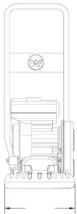
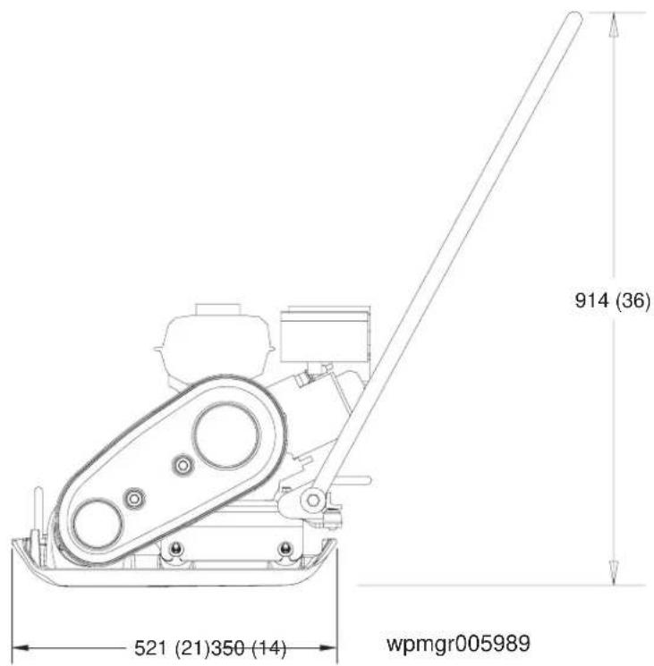
| Dimensions | mm (in.) | 521 (21) x 350 (14) x 914 (36) |
3.3 Sound and Vibration Measurements
The required sound specification, Paragraph 1.7.4.f of 89/392/EEC Machinery Directive, is:
- the guaranteed sound power level (L WA ) = 105 dB(A).
- the sound pressure level at operator's location (L pA ) = 93 dB(A).
These sound values were determined according to ISO 3744 for the sound power level ( LWA ) and ISO 6081 for the sound pressure level ( LpA ) at the operator's location.
The weighted effective acceleration value, determined according to EN ISO 5349, is approximately 4.5 m/s2 .
The sound and vibration measurements were obtained with the machine operating on crushed gravel at nominal engine speed.
Technical Data AP 1135A
3.4 Dimensions
mm (in.)
AP 1135A Operation
4. Operation
4.1 Recommended Fuel
The engine requires regular grade unleaded gasoline. Use only fresh, clean gasoline. Gasoline containing water or dirt will damage fuel system. Consult engine owner's manual for complete fuel specifications.
4.2 Application
This plate is designed for compacting loose, granular soils, gravel, and paving stones. It is intended to be used in confined areas and areas next to structures such as walls, curbs, and foundations. Plates equipped with water tanks can be used for compacting asphalt.
This plate is not recommended for compacting cohesive soils with a heavy clay content. For cohesive soil, use a vibratory rammer or sheepsfoot roller.
4.3 Before Starting
4.3.1 Read and understand the safety and operating instructions at the beginning of this manual.
4.3.2 Check:
- Oil level in the engine
- Fuel level
• Condition of the air cleaner - Tightness of the external fasteners
• Condition of the fuel lines
Operation AP 1135A
4.4 To Start
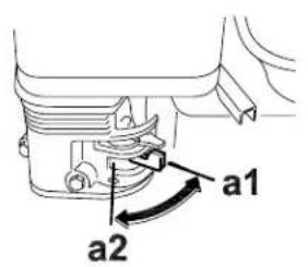
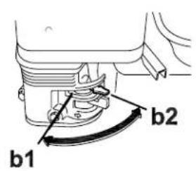
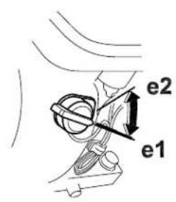
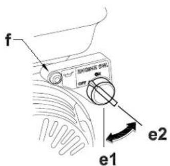
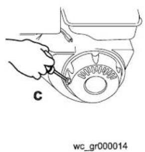
See Graphic: wc_gr000014
4.4.1 Open fuel valve by moving lever to the right (a1).
Note: If engine is cold, move choke lever to close position (b1). If engine is hot, set choke to open position (b2).
4.4.2 Turn engine switch to "ON" (e1).
4.4.3 Open throttle by moving it slightly to left (d1).
4.4.4 Pull starter rope (c).
Note: If the oil level in the engine is low, the engine will not start. If this happens, add oil to engine. Some engines are equipped with an oil alert light (f) that will come on while pulling the starter rope.
4.4.5 Open choke as engine warms (b2).
4.4.6 Open throttle fully to operate.

4.5 To Stop
See Graphic: wc_gr000014
4.5.1 Reduce engine RPM to idle by moving throttle completely to right (d2).
4.5.2 Turn engine switch to "OFF" (e2).
4.5.3 Close fuel valve by moving lever to the left (a2).
AP 1135A Operation
4.6 Operation
Run the engine at full throttle and allow the plate to pull itself along at its normal speed. When operating on an incline it may be necessary to assist the plate by pushing it forward slightly. When operating downhill hold the plate back slightly, if it begins to pick up speed. Depending on the material being compacted, three or four passes are recommended to achieve the best compaction.
While a certain amount of moisture in the soil is necessary, excessive moisture may cause soil particles to stick together and prevent good compaction. If soil is extremely wet, allow it to dry somewhat before compacting.
If soil is so dry as to create dust clouds while operating plate, some moisture should be added to the ground material to improve compaction. This will also reduce service to the air filter.
When using the plate on paving stones, attach a pad to the bottom of the plate to prevent chipping or grinding surface of stones. A special polyurethane pad designed for this purpose is available as an optional accessory.
NOTICE: DO NOT operate the plate on concrete or on extremely hard, dry, compacted surfaces. The plate will jump rather than vibrate and could damage both the plate and the engine.
Maintenance AP 1135A
5. Maintenance
5.1 Periodic Maintenance Schedule
5.1.1 Engine Maintenance
The chart below lists basic engine maintenance. Refer to the engine manufacturer's Operation Manual for additional information.
| Daily before starting | After first 20 hrs. | Every 2 weeks or 50 hrs. | Every month or 100 hrs. | Every year or 300 hrs. | |
| Check fuel level. | ■ | ||||
| Check engine oil level. | ■ | ||||
| Inspect fuel lines. | ■ | ||||
| Inspect air filter. Replace as needed. | ■ | ||||
| Clean air cleaner elements. | ■ | ||||
| Change engine oil. | ■ | ■ | |||
| Clean engine cooling fins. | ■ | ||||
| Clean sediment cup / fuel filter. | ■ | ||||
| Check and clean spark plug. | ■ | ||||
| Check and adjust valve clearance. | ■ | ||||
| Change exciter oil. | ■ |
AP 1135A Maintenance
Machine Maintenance
The chart below lists basic machine maintenance.
| Daily before starting | After first 20 hrs. | Every 2 weeks or 50 hrs. | Every month or 100 hrs. | Every year or 300 hrs. | |
| Check external hardware. | ■ | ||||
| Check and adjust drive belt. | ■ | ■ | |||
| Inspect shockmounts for damage. | ■ | ||||
| Replace shockmounts as needed. | ■ | ||||
| Change exciter oil. | ■ |

Note: When machine is being used in asphalt, it is highly recommended that shockmounts are replaced every year or after 300 hours of usage.
Maintenance AP 1135A
5.2 Spark Plug
See Graphic: wc_gr000028
Clean or replace the spark plug as needed to ensure proper operation. Refer to your engine operator's manual.

The muffler becomes very hot during operation and remains hot for a while after stopping the engine. Do not touch the muffler while it is hot.
Note: Refer to section "Technical Data" for the recommended spark plug type and the electrode gap setting.
5.2.1 Remove the spark plug and inspect it.
5.2.2 Replace the spark plug if the insulator is cracked or chipped.
5.2.3 Clean the spark plug electrodes with a wire brush.
5.2.4 Set the electrode gap (a).
5.2.5 Tighten the spark plug securely.
NOTICE: A loose spark plug can become very hot and may cause engine damage.

AP 1135A Maintenance
5.3 Air Cleaner
See Graphic: wc_gr000025
The engine is equipped with a dual element air cleaner. Service air cleaner frequently to prevent carburetor malfunction.
NOTICE: NEVER run engine without air cleaner. Severe engine damage will occur.

WARNING
NEVER use gasoline or other types of low flash point solvents for cleaning the air cleaner. A fire or explosion could result.
To service:
5.3.1 Remove air cleaner cover (a). Remove both elements and inspect them for holes or tears. Replace damaged elements.
5.3.2 Wash foam element (b) in solution of mild detergent and warm water. Rinse thoroughly in clean water. Allow element to dry thoroughly. Soak element in clean engine oil and squeeze out excess oil.
5.3.3 Tap paper element (c) lightly to remove excess dirt. Replace paper element if it appears heavily soiled.

5.4 Engine Oil
See Graphic: wc_gr000022
5.4.1 Drain the oil while the engine is still warm.
5.4.2 Remove the oil filler plug (a) and the drain plug (b) to drain the oil.
Note: In the interests of environmental protection, place a plastic sheet and a container under the machine to collect any liquid that drains off. Dispose of this liquid in accordance with environmental protection legislation.
5.4.3 Install the drain plug.
5.4.4 Fill the engine crankcase with the recommended oil up to the level of the plug opening (c). See section Technical Data for oil quantity and type.
5.4.5 Install the oil filler plug.

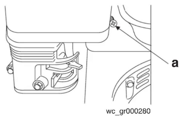
5.5 Adjusting Engine Speed
See Graphic: wc_gr000280
Adjust to a full load speed of 3600 ± 100 rpm.
To adjust engine speed:
5.5.1 Place machine on a rubber test mat to prevent it from moving.
5.5.2 Start engine and allow it to warm up for a minute.
5.5.3 Turn throttle stop screw (a) in to increase speed, out to decrease speed. Make sure throttle lever is touching stop screw before measuring RPM.
NOTICE: Running plate at a speed higher than that listed in Technical Data can damage both the plate and the engine.
AP 1135A Maintenance
5.6 Carburetor Adjustment
See Graphic: wc_gr000032
5.6.1 Start the engine and allow it to warm up to operating temperature.
5.6.2 Set the pilot screw (a) two turns out. See Note.
5.6.3 With the engine idling, turn the pilot screw (a) in or out to the setting that produces the highest rpm.
5.6.4 After the pilot screw is adjusted, turn the throttle stop screw (b) to obtain the standard idle speed. See Technical Data.
Note: On some engines the pilot screw is fitted with a limiter cap (c) to prevent excessive enrichment of the air-fuel mixture in order to comply with emission regulations. The mixture is set at the factory and no adjustment should be necessary. Do not attempt to remove the limiter cap. The limiter cap cannot be removed without breaking the pilot screw.
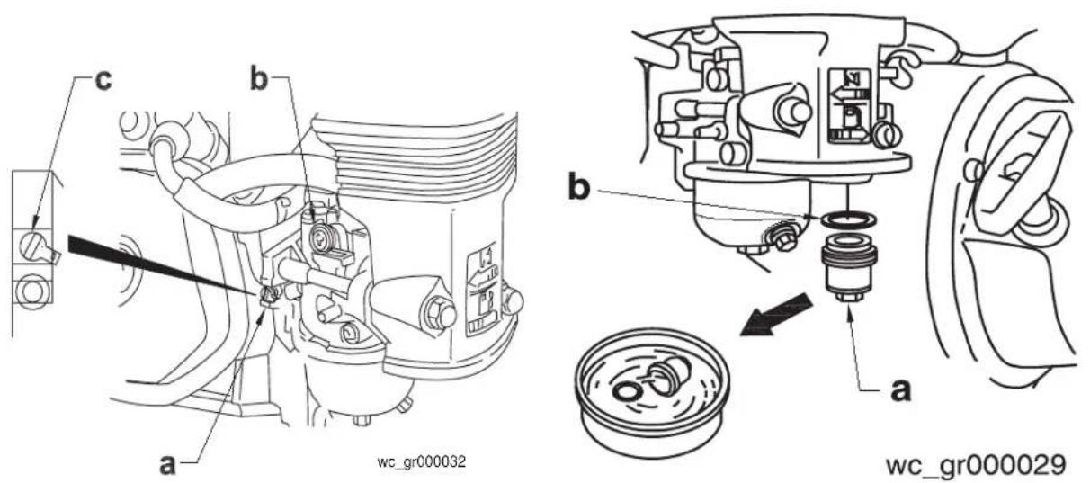
5.7 Cleaning Sediment Cup
See Graphic: wc_gr000029
5.7.1 Turn the fuel valve off.
5.7.2 Remove the sediment cup (a) and the O-ring (b).
5.7.3 Wash both thoroughly in a nonflammable solvent. Dry and reinstall them.
5.7.4 Turn the fuel valve on and check for leaks.
5.8 Drive Belt
See Graphic: wc_gr000290
On new machines or after installing a new belt, check the belt tension after first 20 hours of operation. Check and adjust the belt every 50 hours thereafter.
To adjust the belt:
5.8.1 Loosen the two screws (a) on the beltguard, then remove the beltguard, keeping the screw assemblies captured on the beltguard.
5.8.2 Loosen the four nuts (b) which hold the engine to the console, and the screw (c) which holds the beltguard back to the console.
5.8.3 Slide the engine backward (towards the handle) to tighten the belt, forward to loosen the belt.
5.8.4 Adjust the belt so that it deflects 10-13 mm (3/8in–1/2in) (d) when pressed midway between the belt pulleys.
5.8.5 Make sure that the clutch pulley (f) and the exciter pulley (e) are in alignment. Place a straight edge against the exciter pulley (e) and move the engine so that the two pulleys are parallel.
5.8.6 Torque all nuts and screws to 20.5 Nm (15 ft.lbs.) as you reassemble the machine.

AP 1135A Maintenance
5.9 Exciter Lubrication
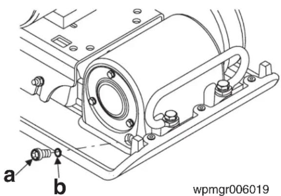
See Graphic: wpmgr006019
The bearings in the exciter assembly are splash lubricated and rotate at very high speed. It is important to maintain the exciter oil at the correct level and change it regularly.
Check oil level in exciter every 50 hours of operation.
To check oil level, place plate on a flat, level surface. Remove the drain plug (a) with seal ring (b). Oil level should be at drain plug threads. Add oil as required.
Change exciter oil every 300 hours of operation.
To drain oil: Remove plug (a) from end of exciter and tilt plate up.
Note: In the interests of environmental protection, place a plastic sheet and a container under the machine to collect any liquid which drains off. Dispose of this liquid in accordance with environmental protection legislation.
Place plate on a level surface and add approximately 210 ml of oil through plug opening until oil reaches the drain plug threads.
NOTICE: DO NOT overfill. Too much oil in exciter can reduce performance and damage drive belt.
5.10 Cleaning the Plate
Clean plate after use to remove dirt, stones, and mud caught under the engine console. If plate is being used in a dusty area, check engine cylinder cooling fins for heavy dirt accumulation. Keep engine cylinder fins clean to prevent engine from overheating.
Maintenance AP 1135A
5.11 Lifting Machine
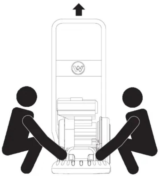
See Graphic: wpmgr006039
See Technical Data for weight of the machine.
To lift machine manually:
5.11.1 Stop the engine.
5.11.2 Obtain help from a partner and plan the lift.

To avoid burns or fire hazards, let the engine cool before transporting the machine or storing it indoors. Turn the fuel valve to the off position and keep the engine level to prevent fuel from spilling.
5.11.3 Grasp machine by the lifting handles (a) and (b).
5.11.4 Lift machine as shown.

To reduce risk of back injury while lifting, keep feet flat on ground and shoulder width apart. Keep head up and back straight.

AP 1135A Maintenance
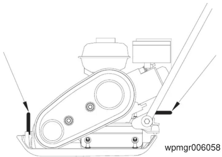
5.12 Transporting Machine
See Graphic: wpmgr006058

To avoid burns or fire hazards, let engine cool before transporting machine or storing indoors.
5.12.1 Turn fuel valve to the off position and keep the engine level to prevent fuel from spilling.
5.12.2 Tie down machine on vehicle to prevent machine from sliding or tipping over. Tie machine to vehicle at points shown on graphic.
5.13 Storage
If plate is being stored for more than 30 days:
5.13.1 Remove loose stones and dirt from plate.
5.13.2 Clean engine cylinder cooling fins.
5.13.3 Clean or replace air filter.
5.13.4 Change exciter oil.
5.13.5 Change engine oil and follow procedures described in engine manual for engine storage.
5.13.6 Cover plate and engine and store in a clean, dry area.
Maintenance AP 1135A
5.14 Troubleshooting
| Problem / Symptom Reason / | Remedy |
| Plate does not develop full speed. Poor compaction. | ·Engine throttle control not completely open.·Throttle control not adjusted correctly.·Ground too wet, plate sticking. Allow soil to dry before compacting.·Drive belt loose or worn, slipping on pulleys. Adjust or replace belt. Check that engine mounting bolts are tight.·Exciter bearings binding. Check condition and level of oil in exciter. Add or change oil.·Air filter clogged with dust, reducing engine performance. Clean or replace air filter.·Engine speed too low. Check engine speed with tachometer. Adjust or repair engine to run at correct speed. Refer to engine manual. |
| Engine running, no vibration · Engine throttle not open. | ·Drive belt loose or broken. Adjust or replace.·Clutch damaged. Inspect and replace clutch.·Engine speed too low. Check engine speed.·Too much oil in exciter. Adjust oil to correct level. |
| Plate jumps or compacts unevenly. | ·Ground surface too hard.·Shockmounts loose or damaged. |
- AP 1135A TABLE OF CONTENTS
- FOREWORD 3
- EMISSION SYSTEM CONTROL INFORMATION 4
- SAFETY INFORMATION 5
- TECHNICAL DATA 12
- OPERATION 15
- TABLE OF CONTENTS AP 1135A
- MAINTENANCE 18
- CALIFORNIA
- PROPOSITION 65 WARNING
- FOREWORD
- EMISSION CONTROL SYSTEM INFORMATION
- 1 EMISSION CONTROL SYSTEMS INFORMATION AND WARRANTY
- 1.1 EMISSION CONTROL SYSTEMS WARRANTY STATEMENT
- AP 1135A SAFETY INFORMATION
- SAFETY INFORMATION
- 2.1 LAWS PERTAINING TO SPARK ARRESTERS
- 2.2 OPERATING SAFETY
- SAFETY INFORMATION AP 1135A
- 2.3 OPERATOR SAFETY WHILE USING INTERNAL COMBUSTION ENGINES
- 2.4 SERVICE SAFETY
- 2.5 LABEL LOCATIONS
- 2.6 WARNING AND INFORMATIONAL LABELS
- TECHNICAL DATA AP 1135A
- TECHNICAL DATA
- 3.1 ENGINE DATA
- ENGINE POWER RATING
- AP 1135A TECHNICAL DATA
- 3.2 MACHINE DATA
- 3.3 SOUND AND VIBRATION MEASUREMENTS
- 3.4 DIMENSIONS
- AP 1135A OPERATION
- OPERATION
- 4.1 RECOMMENDED FUEL
- 4.2 APPLICATION
- 4.3 BEFORE STARTING
- OPERATION AP 1135A
- 4.4 TO START
- 4.5 TO STOP
- 4.6 OPERATION
- MAINTENANCE AP 1135A
- MAINTENANCE
- 5.1 PERIODIC MAINTENANCE SCHEDULE
- 5.1.1 ENGINE MAINTENANCE
- AP 1135A MAINTENANCE
- 5.2 SPARK PLUG
- 5.3 AIR CLEANER
- 5.4 ENGINE OIL
- 5.5 ADJUSTING ENGINE SPEED
- 5.6 CARBURETOR ADJUSTMENT
- 5.7 CLEANING SEDIMENT CUP
- 5.8 DRIVE BELT
- 5.9 EXCITER LUBRICATION
- 5.10 CLEANING THE PLATE
- 5.11 LIFTING MACHINE
- 5.12 TRANSPORTING MACHINE
- 5.13 STORAGE
- 5.14 TROUBLESHOOTING
Brand : Wacker Neuson
Model : VP 1135A
Category : Vibratory plate