USER MANUAL Thision S PLUS Elco
natural_image
3D rendered image of a hand pointing at a button (no text or symbols visible)
natural_image
Front view of a gray industrial control panel with a digital display and rotary knob (no visible text or symbols)
Grundlagen
Legende:
Programmierung
Ladevorrang Speicher
line
| t | Bx | On | Off |
| ---- | ---- | ---- | ---- |
| Peak | | | |
| Low | | | |
| High | | | |
| Low | | | |
| High | | | |
| High | | | |
| Low | | | |
| High | | | |
| High | | | |
| Low | | | |
| High | | | |
| High | | | |
| Low | | | |
| High | | | |
| High | | | |
| Low | | | |
| High | | | |
| High | | | |
| Low | | | |
|
| High | | | |
| High | | | |
| Low | | | |
| High | | | |
| High | | | |
| Low | | | |
| High | | | |
| High | | | |
| Low | | | |
| High | | | |
| High | | - 100% from T to T - 100% from T - 100% from T - 100% from T - 100% from T - 100% from T - 100% from T - 100% from T - 100% from T - 100% from T - 100% from T - 100% from T - 100% from T - 100% from T - 50% from T - 100% from T - 100% from T - 100% from T - 100% from T - 100% from T - 100% from T - 100% from T - 100% from T - 100% from T - 100% from T - 100% from T - 50% from T = 50% to T = 50% from T = 50% to T = 100% from T = 50% to T = 100% from T = 100% to T = 100% from T = 100% to T = 100% from T = 100% to T = 50% from T = 50% to T = 100% from T = 50% to T = 100% from T = 50% to T = 100% from T = 50% to T = 50% from T = 50% to T = 100% from T = 50% to T = 100% from T = 50% to T = 100% from T = 50% to T = 50%.
TKx Kesseltemperatur
Bx Vergleichs-Isttemperatur
On/Off Kesselpumpe
SDon Temperaturdifferenz EIN
SDoff Temperaturdifferenz
AUS
line
| Time Segment | Signal |
| ------------ | ---------- |
| Start | TBWw |
| Peak | TBWR |
| Mid | SDBW |
| Peak | TBWx |
| Mid | 2*SDBW |
| End | SDBW |
Anlagenhydraulik
2. Pumpenstufe Q21, Q22, Q23
natural_image
3D rendered image of a hand pointing at a button (no text or symbols visible)

natural_image
Front view of a control panel with digital display and rotary knob (no visible text or symbols)
Fondamenti
Tasto modo operativo ACS (M)
Programmazione
line
| t | TRx | TRw+SDR |
| ---- | ----- | ------- |
| ON | | |
| OFF | | |
Boiler pump on heat gen lock
Fan speed full charging max
Fan shutdown heating mode
Rilascio integr. seq. sorg.
Charging time relative prio
Waiting time relative prio
line
| t | Bx | On | Off |
| ---- | ---- | ---- | ---- |
| Low | Low | Low | Low |
| Peak | High | High | High |
| Mid | Low | Low | Low |
| High | High | High | High |
Stato Bus power supply
Contr. stop setpoint
natural_image
3D rendered image of a hand pointing at a button (no text or symbols visible)

natural_image
Front view of a control panel with digital display and rotary buttons (no visible text or symbols)
Table of Contents
Basics
Product description, Features, Functionality ....3
Controls....4
Display / Programming ....5
Overview of main functions 6
Parameters Enduser 7
Parameters professional installer....10
Info menu / Manual control / Chimney sweeper function / Controller stop.....33
Error messages / Maintenance ....34
Detailed settings
Menu time of day and date....37
Menu Operator section....38
Menu Time programs / Holiday 39
Menu Heating circuits....40
Menu DHW....51
Menu Consumer circuit ....55
Menu Swimming pool 56
Menu Primary controller / system pump 57
Menu Boiler 59
Menu Cascade 64
Menu Solar....66
Menu Solid fuel boiler....70
Menu Buffer storage tank....71
Menu Fault, Service/special operation 91
Menu Input/output test, State 94
Menu Diagnostics....95
Menu Burner control....96
Notes 97
Product description, Features, Functionality
Product description
The LMS controller is a weather compensated digital controller that can control two mixed heating zones, DHW preparation, do cascading and burner control.
Additional functions can be activated. The controller calculates the required temperatures for the boiler and the heating zones according to the outside temperature and controls DHW preparation. With additional optimizing functionality optimal energy savings can be achieved.
Features
Heating zone control with the following functions:
• Operation mode Heating, DHW
- Setpoint adjustment for Heating, DHW
- Info button
- Manual control
• Chimney sweeper function
- Reset button
Functionality
- Weather compensated heating zone controller for max. 2 mixed heating zones. DHW control with enable and setpoint adjustment.
- programmable time controlled circulation pump
- Illuminated display, multi lingual clear text for status and function indication
• Automatic summer/winter change over
- Preprogrammed time programmes for Heating and DHW
- Individual time program with periods according to controller system configuration
- Holiday program for each heating zone
- Emission control / Chimney sweeper with automatic return to normal operation
- Floor curing function
• Storage tank management
- Heat generation lock
• External setpoint via 0-10Vdc
• Solar DHW Heating functionality
- Programmable swimming pool control
- Integrated Cascade functionality for multiple boiler installation
• Room temperature control via accesory QAA 75 / 78
• QAA 75 via 2-wire Bus
• QAA 78 via wireless connection
- Adjustment of radiator or underfloor heating zones with adjustment of time programs
• Automatic heat slope adaption programmable
- Heat up optimization with quick start programmable
- Demand dependant cool down
- Adjustable minimum and maximum flow temperatures
- Pump post run
- Integrated hour counter
- anti-legionella function
- Boiler and system antifrost
- 2-wire bus connection for controller accessories
- LPB-Bus functionality via optional OCI 345
Operating instructions
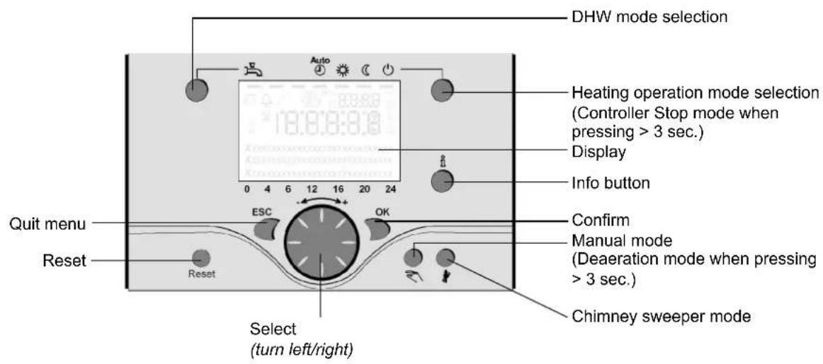
Controls
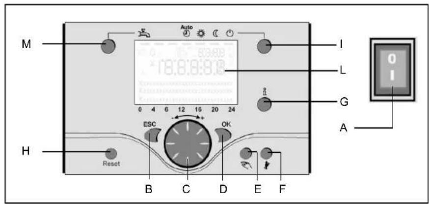
Legend:
A On/off switch
B Return (ESC)
C Room temperature control
D Confirmation (OK)
E Manual mode
F Chimney sweeper mode
G Info mode
H Reset button
I Operation mode heating zone(s)
L Display
Operation mode heating zone(s) (I)
For setting 4 different heating modes: Auto (clock): Automatic operation by time program
Comfort (sun): 24/7 heating in comfort mode
Reduction (moon): 24/7 heating in reduced mode
Standby: heating off, frost protection activated.
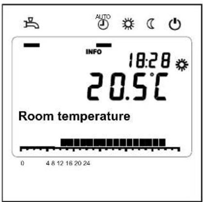
Display (L)
Info mode (G)
Display possibility of following info without influence on boiler control:
temperatures, operation mode
Room temperature control (C)
- for changing room comfort temperature
- for changing setting when programming.
Confirmation (OK) (D)
Return (ESC) (B)
These buttons are used for programming in combination with the rotary knob.
By pressing the ESC button it's possible to go back one level, changed values are not taken over by the controller.
By pressing the OK button it's possible to arrive in the next level or confirm changed values.
Manual mode (E)
This button is used for switching the boiler into manual mode. In manual mode all pumps will run and the mixing valves are no longer controlled, the burner setpoint is 60°C (indicated by spanner symbol).
On/off switch (A)
Position 0:
Boiler and connected electrical components are no powered. Frost protection is not secured.
Position I
The boiler and connected electrical components are powered and standby for operation.
Deaeration mode (E)
By pressing the manual mode button longer than 3 seconds, the automatic hydraulic deaeration is activated. During deaeration the system is put in standby mode
The pumps are switched on and off for several times.
After deaeration, the boiler automatically returns to normal operation.
Chimney sweeper mode (F)
Used for combustion analysis. By pressing the button once again, or automatically after 15 minutes, the chimney sweeper mode will be deactivated (indicated by spanner symbol).
By shortly pressing the reset button a burner lockout can be cancelled.
Operating instructions
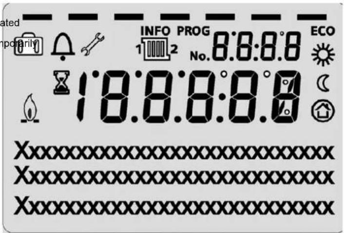
Display / Programming

Heating to comfort setpoint Info level activated

Heating to reduced setpoint Programming activated

Heating for frost protection setpoint Heating tem switched off

Process running – please wait

Burner operating (only oil / gas boiler)

Error messages
INFO
Info level active
PROG
Programming active
ECO
Heating temporarily switched off ECO function

Holiday function active

Reference to heating circuit

Maintenance / special operation
No.
Parameter number
Programming
Default mode (buttons)
Press OK (1x)
Press INFO (4 sec.)
Enduser
- choose menu
- confirm with OK button
- choose parameter
- confirm with OK button
- change value + - with rotary knob
- confirm with OK button
- return to main menu with ESC button
Commissioning Expert
choose user level
- confirm with OK button
- choose menu
- confirm with OK button
- choose parameter
- confirm with OK button
- change value + - with rotary knob
- confirm with OK button
- return to main menu with ESC button
Overview of main functions
| Button | Action | Procedure | Display / Function |
 | Set room temperature | Zone 1 and zone 2Actuate rotary knob left/rightTurn rotary knobConfirm with OK buttonor wait 5 sec.or press [IMAGE] | Comfort setpoint with blinking temperatureBlinking temperature in 0,5 °C steps from 10 to 30 °CComfort setpoint savedComfort setpoint cancelled- after 3 sec. Main menu appears |
 | Set room temperature for zone 1 or zone 2 | Zone 2 independent from zone 1Actuate rotary knob left/rightConfirm with OK buttonActuate rotary knob left/rightConfirm with OK buttonor wait 5 sec.or press [IMAGE] | Choose heating zoneHeating zone is chosenBlinking temperature in 0,5 °C steps from 10 to 30 °CComfort setpoint savedComfort setpoint cancelled- after 3 sec. Main menu appears |
 | Switch on /off DHW operation | Press button | DHW mode on / off(see indication below DHW symbol)- On: DHW mode by time programm- Off: no DHW operation- Safety functions activated |
 | Change heating operation mode | Factory settingPress button 1xPress button 1x againPress button 1x again | Automatic mode on, with:- Heating by time programmtemperature setpoint by heating programmt-Safety functions activated- Summer/Winter automatic switching activated- ECO-functions activated(see indication below operation symbol)Continuous COMFORT heating on, with:- Heating without time programmt by comfort setpoint- Safety functions activatedContinuous REDUCED heating on, with:- Heating without time programmt by reduced setpoint- Safety functions activated- Summer/Winter automatic switching activated- ECO-functions activatedSafety mode on, with:- Heating off- Temperature by frost protection- Safety functions activated |
| Controller Stop mode Press | Press button > 3 sec.Press button > 3 sec. again | 304: Controller Stopp mode insert setpointafter 3 sec. Main menu appears |
| [W644] | Info display | Press button 1xPress button 1x againPress button 1x again......Press button 1x | INFO Segment displayed- Status Boiler - room temperature- room temperature minimum- Status DHW - room temperature maximum- Status zone 1 - outside temperature- Status zone 2 - outside temperature minimum- outside temperature maximum- Time / Date - DHW temperature 1- Error indication - Boiler temperature- Maintenance indication - Flow temperature(Info display depends on configuration)Back to main menu; INFO Segment disappears |
 | Operation by manual setpointChange factory setting boiler temperature | Press button 1xPress button [IMAGE]Turn rotary knob -/+Press button [IMAGE]Press button [IMAGE] | Manual mode on (spanner symbol appears)- Haeting by fixed setpoint(factory setting = 60 °C)301: Manual mode insert setpoint?blinking temperatureset valueStatus boilerManual mode off (spanner symbol disappears) |
| Deaeration | Press button > 3 sec.Press button > 3 sec. again | 312: Deaeration onDeaeration off |
| Activate chimney sweeper mode | Press button (< 3 sec.)Press button again (< 3 sec.) | Chimney sweeper mode onChimney sweeper mode off |
| Temporary reduction of reduced temperature on QAA75 | Press buttonPress button again | Heating by reduced setpointHeating by comfort setpoint |
| RESET | Reset button Press button | (< 3 sec.)Press button again > 3 sec. | Boiler manually blocked, no releaseBoiler released, Alarm symbol disappears |
- Main display "Boiler temperature"
- Press OK Button 1x
- Turn the rotary knob to select for example menu "DHW"
- Press OK Button 1x
- Turn the rotary knob to select for example parameter 1612 "DHW temperature reduced setpoint" in menu "DHW"
- Press OK Button 1x
- Turn the rotary knob to change the setting
- Press OK Button 1x > new setting has been stored
- Press ESC Button 2x to go back to main display "Boiler temperature"
| Menu | Line no. | Operating line | Unit | Min. | Max | Factory setting* |
| Time of day and date | 1 | Hours / Minutes | hh:mm | 00:00 | 23.59 | |
| 2 | Day / Month | tt:MM | 01.01 | 31.12. | |
| 3 | Year | jjjj | 2004 | 2099 | |
| Operator section | 20 | Language | - | English, Deutsch, Francais, Italiano, Dansk, Nederlands, Español, Česky, Slovenský, Türksçe | |
| Time program HC 1 | 500 | Preselection | - | Mo-Su, Mo-Fr, Sa-Su, Mo,Tu,We,Th,Fr,Sa,Su | |
| 501 | Mo-Su: 1. Phase On | hh:mm | 00:00 | 24:00 | |
| 502 | Mo-Su: 1. Phase Off | hh:mm | 00:00 | 24:00 | |
| 503 | Mo-Su: 2. Phase On | hh:mm | 00:00 | 24:00 | |
| 504 | Mo-Su: 2. Phase Off | hh:mm | 00:00 | 24:00 | |
| 505 | Mo-Su: 3. Phase On | hh:mm | 00:00 | 24:00 | |
| 506 | Mo-Su: 3. Phase Off | hh:mm | 00:00 | 24:00 | |
| 516 | Default values | - | Yes, No | |
| Time program HC 2(When activated) | 520 | Preselection | - | Mo-Su, Mo-Fr, Sa-Su, Mo,Tu,We,Th,Fr,Sa,Su | |
| 521 | Mo-Su: 1. Phase On | hh:mm | 00:00 | 24:00 | |
| 522 | Mo-Su: 1. Phase Off | hh:mm | 00:00 | 24:00 | |
| 523 | Mo-Su: 2. Phase On | hh:mm | 00:00 | 24:00 | |
| 524 | Mo-Su: 2. Phase Off | hh:mm | 00:00 | 24:00 | |
| 525 | Mo-Su: 3. Phase On | hh:mm | 00:00 | 24:00 | |
| 526 | Mo-Su: 3. Phase Off | hh:mm | 00:00 | 24:00 | |
| 536 | Default values | - | Yes, No | |
| Time program 3/HC3(When activated) | 540 | Preselection | - | Mo-Su, Mo-Fr, Sa-Su, Mo,Tu,We,Th,Fr,Sa,Su | |
| 541 | Mo-Su: 1. Phase On | hh:mm | 00:00 | 24:00 | |
| 542 | Mo-Su: 1. Phase Off | hh:mm | 00:00 | 24:00 | |
| 543 | Mo-Su: 2. Phase On | hh:mm | 00:00 | 24:00 | |
| 544 | Mo-Su: 2. Phase Off | hh:mm | 00:00 | 24:00 | |
| 545 | Mo-Su: 3. Phase On | hh:mm | 00:00 | 24:00 | |
| 546 | Mo-Su: 3. Phase Off | hh:mm | 00:00 | 24:00 | |
| 556 | Default values | - | Yes, No | |
*See manual boiler
| Menu | Line no. | Operating line | Unit | Min. | Max | Factory setting* |
| Time program 4/DHW | 560 | Preselection | - | Mo-Su, Mo-Fr, Sa-Su, Mo,Tu,We,Th,Fr,Sa,Su | |
| 561 | Mo-Su: 1. Phase On | hh:mm | 00:00 | 24:00 | |
| 562 | Mo-Su: 1. Phase Off | hh:mm | 00:00 | 24:00 | |
| 563 | Mo-Su: 2. Phase On | hh:mm | 00:00 | 24:00 | |
| 564 | Mo-Su: 2. Phase Off | hh:mm | 00:00 | 24:00 | |
| 565 | Mo-Su: 3. Phase On | hh:mm | 00:00 | 24:00 | |
| 566 | Mo-Su: 3. Phase Off | hh:mm | 00:00 | 24:00 | |
| 576 | Default values | - | Yes | No | |
| Time program 5 | 600 | Preselection | - | Mo-Su, Mo-Fr, Sa-Su, Mo,Tu,We,Th,Fr,Sa,Su | |
| 601 | Mo-Su: 1. Phase On | hh:mm | 00:00 | 24:00 | |
| 602 | Mo-Su: 1. Phase Off | hh:mm | 00:00 | 24:00 | |
| 603 | Mo-Su: 2. Phase On | hh:mm | 00:00 | 24:00 | |
| 604 | Mo-Su: 2. Phase Off | hh:mm | 00:00 | 24:00 | |
| 605 | Mo-Su: 3. Phase On | hh:mm | 00:00 | 24:00 | |
| 606 | Mo-Su: 3. Phase Off | hh:mm | 00:00 | 24:00 | |
| 616 | Default values | - | Yes | No | |
| Holidays HC1 | 641 | Preselection | - | Period 1, 2, 3, 4, 5, 6, 7, 8 | |
| 642 | Period Start Day / Month | tt.MM | 01.01 | 31.12 | |
| 643 | Periode End Day / Month | tt.MM | 01.01 | 31.12 | |
| 648 | Operating level | - | Frost protection, Reduced | |
| Holidays HC2 (When activated) | 651 | Preselection | - | Period 1, 2, 3, 4, 5, 6, 7, 8 | |
| 652 | Period Start Day / Month | tt.MM | 01.01 | 31.12 | |
| 653 | Periode End Day / Month | tt.MM | 01.01 | 31.12 | |
| 658 | Operating level | - | Frost protection, Reduced | |
| HC1 | 710 | Comfort setpoint | °C | Value from Line no. 712 | 35 | |
| 712 | Reduced setpoint | °C | 4 | Value from Line no. 710 | |
| 714 | Frost protection setpoint | °C | 4 | Value from Line no. 712 | |
| 720 | Heating curve slope | - | 0.10 | 4.00 | |
| 730 | Summer/winter heating limit | °C | ---/8 | 30 | |
| HC2 (When activated) | 1010 | Comfort setpoint | °C | Value from Line no. 1012 | 35 | |
| 1012 | Reduced setpoint | °C | 4 | Value from Line no. 1010 | |
| 1014 | Frost protection setpoint | °C | 4 | Value from Line no. 1012 | |
| 1020 | Heating curve slope | - | 0.10 | 4.00 | |
| 1030 | Summer/winter heating limit | °C | ---/8 | 30 | |
| DHW | 1610 | Nominal setpoint | °C | Value from Line no. 1612 | 80 | |
| 1612 | Reduced setpoint | °C | 8 | Value from Line no. 1610 | |
*See manual boiler
Parameters Enduser
| Menu | Line no. | Operating line | Unit | Min. | Max | Factory setting* |
| Swimming pool | 2055 | Pool setpoint solar heating | °C | 8 | 80 | |
| 2056 | Pool sepoint boiler heating | °C | 8 | 80 | |
| Boiler | 2214 | Setpoint manual control | °C | 10 | 90 | |
| Fault | 6705 | SW Diagnose Code | - | - | - | Indication only |
| 6706 | Burner ctrl phase lockout pos | - | - | - | Indication only |
*See manual boiler
- Main display "Boiler temperature"
- Press OK Button 1x
- Press Info Button > 3s
- Turn the rotary knob to select level "Commissioning" or "Engineer"
- Press OK Button 1x
- Turn the rotary knob to select for example menu "DHW"
- Press OK Button 1x
- Turn the rotary knob to select for example parameter 1612 "DHW temperature reduced setpoint" in menu "DHW"
- Press OK Button 1x
- Turn the rotary knob to change the setting
- Press OK Button 1x > new setting has been stored
- Press ESC Button 2x to go back to main display "Boiler temperature"
Access via "Commissioning" level will only show the parameters in grey.
Access via "Engineer" level will show all parameters.
*See manual boiler
| Menu | Line no. | Operating line | Unit | Min. | Max | Factory setting* |
| Time of day and date | 1 | Hours / Minutes | hh:mm | 00:00 | 23.59 | |
| 2 | Day / Month | tt:MM | 01.01 | 31.12. | |
| 3 | Year | jjjj | 2004 | 2099 | |
| 5 | Start of summertime Day / Month | tt:MM | 01.01 | 31.12. | |
| 6 | End of summertime Day / Month | tt.MM | 01.01 | 31.12. | |
| Operator section | 20 | Language | - | English, Deutsch Francais, Italiano, Nederlands Polski | |
| 22 | Info | - | Temporarily, Permanently | |
| 26 | Operation lock | - | Off, On | |
| 27 | Programming lock | - | Off, On | |
| 28 | Direct adjustment | - | Automatic storage, Storage with confirmation | |
| 44 | Operation HC2 | - | Jointly with HC1, Independently | |
| 46 | Operation HC3/P | - | Jointly with HC1, Independently | |
| 70 | Software Version | - | 0 | 99.0 | |
| Time program HC 1 | 500 | Preselection | - | Mo-Su, Mo-Fr, Sa-Su, Mo,Tu,We,Th,Fr,Sa,Su | |
| 501 | Mo-Su: 1. Phase On | hh:mm | 00:00 | 24:00 | |
| 502 | Mo-Su: 1. Phase Off | hh:mm | 00:00 | 24:00 | |
| 503 | Mo-Su: 2. Phase On | hh:mm | 00:00 | 24:00 | |
| 504 | Mo-Su: 2. Phase Off | hh:mm | 00:00 | 24:00 | |
| 505 | Mo-Su: 3. Phase On | hh:mm | 00:00 | 24:00 | |
| 506 | Mo-Su: 3. Phase Off | hh:mm | 00:00 | 24:00 | |
| 516 | Default values | - | Yes, No | |
| Time program HC 2 (when activated) | 520 | Preselection | - | Mo-Su, Mo-Fr, Sa-Su, Mo,Tu,We,Th,Fr,Sa,Su | |
| 521 | Mo-Su: 1. Phase On | hh:mm | 00:00 | 24:00 | |
| 522 | Mo-Su: 1. Phase Off | hh:mm | 00:00 | 24:00 | |
| 523 | Mo-Su: 2. Phase On | hh:mm | 00:00 | 24:00 | |
| 524 | Mo-Su: 2. Phase Off | hh:mm | 00:00 | 24:00 | |
| 525 | Mo-Su: 3. Phase On | hh:mm | 00:00 | 24:00 | |
| 526 | Mo-Su: 3. Phase Off | hh:mm | 00:00 | 24:00 | |
| 536 | Default values | - | Yes, No | |
| Time program HC3/P | 540 | Preselection | - | Mo-Su, Mo-Fr, Sa-Su, Mo,Tu,We,Th,Fr,Sa,Su | |
| 541 | Mo-Su: 1. Phase On | hh:mm | 00:00 | 24:00 | |
| 542 | Mo-Su: 1. Phase Off | hh:mm | 00:00 | 24:00 | |
| 543 | Mo-Su: 2. Phase On | hh:mm | 00:00 | 24:00 | |
| 544 | Mo-Su: 2. Phase Off | hh:mm | 00:00 | 24:00 | |
| 545 | Mo-Su: 3. Phase On | hh:mm | 00:00 | 24:00 | |
| 546 | Mo-Su: 3. Phase Off | hh:mm | 00:00 | 24:00 | |
| 556 | Default values | - | Yes, No | |
| Time program 4 DHW | 560 | Preselection | - | Mo-Su, Mo-Fr, Sa-Su, Mo,Tu,We,Th,Fr,Sa,Su | |
| 561 | Mo-Su: 1. Phase On | hh:mm | 00:00 | 24:00 | |
| 562 | Mo-Su: 1. Phase Off | hh:mm | 00:00 | 24:00 | |
| 563 | Mo-Su: 2. Phase On | hh:mm | 00:00 | 24:00 | |
| 564 | Mo-Su: 2. Phase Off | hh:mm | 00:00 | 24:00 | |
| 565 | Mo-Su: 3. Phase On | hh:mm | 00:00 | 24:00 | |
| 566 | Mo-Su: 3. Phase Off | hh:mm | 00:00 | 24:00 | |
| 576 | Default values | - | Yes, No | |
| Time program 5 | 600 | Preselection - | | Mo-Su, Mo-Fr, Sa-Su, Mo,Tu,We,Th,Fr,Sa,Su | |
| 601 | Mo-Su: 1. Phase On | hh:mm | 00:00 | 24:00 | |
| 602 | Mo-Su: 1. Phase Off | hh:mm | 00:00 | 24:00 | |
| 603 | Mo-Su: 2. Phase On | hh:mm | 00:00 | 24:00 | |
| 604 | Mo-Su: 2. Phase Off | hh:mm | 00:00 | 24:00 | |
| 605 | Mo-Su: 3. Phase On | hh:mm | 00:00 | 24:00 | |
| 606 | Mo-Su: 3. Phase Off | hh:mm | 00:00 | 24:00 | |
| 616 | Default values | - | Yes, No | |
| Holidays HC1 | 641 | Preselection | - | Period 1, 2, 3, 4, 5, 6, 7, 8 | |
| 642 | Period Start Day / Month | tt.MM | 01.01 | 31.12 | |
| 643 | Periode End Day / Month | tt.MM | 01.01 | 31.12 | |
| 648 | Operating level | - | Frost protection | |
| Holidays HC2(When activated) | 651 | Preselection | - | Period 1, 2, 3, 4, 5, 6, 7, 8 | |
| 652 | Period Start Day / Month | tt.MM | 01.01 | 31.12 | |
| 653 | Periode End Day / Month | tt.MM | 01.01 | 31.12 | |
| 658 | Operating level | - | Frost protection | |
| HC 1 | 700 | Operating mode HC1 | - | Protection, Automatic mode,Continuously comfort, Continuously reduced | |
| 710 | Comfort setpoint | °C | Value from Line no. 712 | 35 | |
| 712 | Reduced setpoint | °C | Value from Line no. 714 | Value from Line no. 710 | |
| 714 | Frost protection setpoint | °C | 4 | Value from Line no. 712 | |
| 720 | Heating curve slope | - | 0.10 | 4.00 | |
| 721 | Heating curve parallel displacement | °C | -4.5 | 4.5 | |
| 726 | Heating curve adaption | °C | Off, On | |
| 730 | Summer/winter heating limit | °C | ---/8 30 | | |
| 732 | 24-hour heating limit | °C | ---/-10 10 | | |
| 733 | Ext'n 24-hour heating limit | - | No, Yes | |
| 740 | Flow temp setpoint min | °C | 8 | Value from Line no. 741 | |
| 741 | Flow temp setpoint max | °C | Value from Line no. 740 | 80 | |
| 742 | Flow temp setpoint room stat | °C | Value from Line no. 740 | Value from Line no. 741 | |
| 746 | Delay heat request | s | 0 | 600 | |
| 750 | Room influence | % | ---/0 | 100 | |
| 760 | Room temp limitation | °C | ---/0.5 4 | | |
| 770 | Boost heating | °C | ---/0 20 | | |
| 780 Quick setback - | | Off, Down to Reduced setpoint,Down to Frost protection setpoint | |
| 790 | Optimum start control max | min | 0 | 360 | |
| 791 | Optimum Stop control max | min | 0 | 360 | |
| 800 | Reduced setp increase start | °C | ---/30 | 10 | |
| 801 | Reduced setp increase end | °C | -30 | Value from Line no. 800 | |
| 820 | Overtemp prot pump circuit | - | Off, On | |
| 830 | Mixing valve boost | °C | 0 | 50 | |
| 832 | Actuator type | - | 2-position, 3-position | |
| 833 | Switching differential 2-pos | °C | 0 | 20 | |
| 834 | Actuator running time | s | 30 | 873 | |
| 835 | P-Band (Xp) HC1 | °C | 1 | 100 | |
| 836 | Integral action time (Tn) HC1 | s | 10 | 873 | |
| Menu | Line no. | Operating line | Unit | Min. | Max | Factory setting* |
| HC 1 | 850 Floor curing function - | | Off, Functional heating, Curing heating, Functional/Curing heating, Manually | |
| 851 | Floor curing setp manually | °C | 0 | 95 | |
| 855 | Floor curing setp current | °C | - | Indication only |
| 856 | Floor curing day current | - | - | Indication only |
| 861 | Excess heat draw | - | Off, Heating mode, Always | |
| 870 | With buffer | - | No, Yes | |
| 872 | With prim contr/system pump | - | No, Yes | |
| 890 | Flow setp readj speed ctrl | - | No, Yes | |
| 898 | Operating level change over | - | Frost protection, Reduced, Comfort | |
| 900 | Optg mode changeover | - | None, Protection, Reduced, Comfort, Automatic | |
| HC 2 (when activated) | 1000 | Operating mode HC2 | - | Protection, Automatic mode, Continuously comfort, Continuously reduced | |
| 1010 | Comfort setpoint | °C | Value from Line no. 1012 | 35 | |
| 1012 | Reduced setpoint | °C | Value from Line no. 1014 | Value from Line no. 1010 | |
| 1014 | Frost protection setpoint | °C | 4 | Value from Line no. 1012 | |
| 1020 | Heating curve slope | - | 0.10 | 4.00 | |
| 1021 | Heating curve parallel displacement | °C | -4.5 | 4.5 | |
| 1026 | Heating curve adaption | °C | Off, On | |
| 1030 | Summer/winter heating limit | °C | ---/8 | 30 | |
| 1032 | 24-hour heating limit | °C | ---/-10 10 | | |
| 1033 | Ext'n 24-hour heating limit | - | No, Yes | No, Yes | |
| 1040 | Flow temp setpoint min | °C | 8 | Value from Line no. 1041 | |
| 1041 | Flow temp setpoint max | °C | Value from Line no. 1040 | 80 | |
| 1042 | Flow temp setpoint room stat | °C | Value from Line no. 1040 | Value from Line no. 1041 | |
| 1050 | Room influence | % | ---/0 | 100 | |
| 1060 | Room temp limitation | °C | ---/0.5 | 4 | |
| 1070 | Boost heating | °C | ---/0 | 20 | |
| 1080 | Quick setback | - | Off, Down to Reduced setpoint, Down to Frost protection setpoint | |
| 1090 | Optimum start control max | min | 0 | 360 | |
| 1091 | Optimum Stop control max | min | 0 | 360 | |
| 1100 | Reduced setp increase start | °C | ---/30 | 10 | |
| 1101 | Reduced setp increase end | °C | -30 | Value from Line no. 1100 | |
| 1120 | Overtemp prot pump circuit | - | Off, On | |
| 1130 | Mixing valve boost | °C | 0 | 50 | |
| 1132 | Actuator type | - | 2-position, 3-position | |
| 1133 | Switching differential 2-pos | °C | 0 | 20 | |
| 1134 | Actuator running time | s | 30 | 873 | |
| 1135 | P-Band (Xp) HC1 | °C | 1 | 100 | |
| 1136 | Integral action time (Tn) HC1 | s | 10 | 873 | |
| 1150 | Floor curing function | - | Off, Functional heating, Curing heating, Functional/Curing heating, Manually | |
| 1151 | Floor curing setp manually | °C | 0 | 95 | |
| 1155 | Floor curing setp current | °C | - | - | Indication only |
| 1156 | Floor curing day current | - | - | - | Indication only |
| 1161 | Excess heat draw | - | Off, Heating mode, Always | |
| 1170 | With buffer | - | No, Yes | |
| 1172 | With prim contr/system pump | - | No, Yes | |
| 1190 | Flow setp readj speed ctrl | - | No, Yes | |
| 1198 | Operating level change over | - | Frost protection, Reduced, Comfort | |
| 1200 | Optg mode changeover | - | None, Protection, Reduced, Comfort, Automatic | |
| Domestic hot water | 1600 | Operating mode | - | Off, On, Eco | |
| 1610 | Nominal setpoint | °C | 8 | 80 | |
| 1612 | Reduced setpoint | °C | 8 | 80 | |
| 1620 Release | - | 24h/Day, Time programs HCs, Time program 4/DHW | |
| 1630 | Charging priority | - | Absolute, Shifting, None, MC shifting PC absolute | |
| 1640 | Legionella function | - | Off, Periodically, Fixed weekday | |
| 1641 | Legionella function periodically | - | 1 | 7 | |
| 1642 | Legionella funct Day | - | Mo,Tu,We,Th,Fr,Sa,Su | |
| 1644 | Legionella funct time | h:m | 00:00 | 23:50 | |
| 1645 | Legionella funct setpoint | °C | 55 | 95 | |
| 1646 | Legionella funct duration | min | 10 | 360 | |
| 1647 | Legionella funct circ pump | - | Off, On | |
| 1660 | Circulating pump release | - | Time program 3/HCP, DHW release, Time program 4/DHW, Time program 5 | |
| 1661 | Circulating pump cycling | - | Off, On | |
| 1663 | Circulation setpoint | °C | 8 | 80 | |
| 1680 | Optg mode changeover | - | None, Off, On | |
| Consumer circuit 1 | 1859 | Flow temp setp cons request | °C | 8 | 120 | |
| 1874 | DHW charging priority | - | No, Yes | |
| 1875 | Excess heat draw | - | Off, On | |
| 1878 | With buffer | - | No, Yes | |
| 1880 | With prim contr/system pump | - | No, Yes | |
| Consumer circuit 2 | 1909 | Flow temp setp cons request | °C | 8 | 120 | |
| 1924 | DHW charging priority | - | No, Yes | |
| 1925 | Excess heat draw | - | Off, On | |
| 1928 | With buffer | - | No, Yes | |
| 1930 | With prim contr/system pump | - | No, Yes | |
| Swimming pool circuit | 1959 | Flow temp setpoint | °C | 8 | |
| 1974 | DHW charging priority | - | No, Yes | |
| 1975 | Excess heat draw | - | Off, On | |
| 1978 | With buffer | - | No, Yes | |
| 1980 | With prim contr/system pump | - | No, Yes | |
| Swimming pool | 2055 | Pool setpoint solar heating | °C | 8 | 80 | |
| 2056 | Pool setpoint producer heating | °C | 8 | 80 | |
| 2065 | Pool charging priority solar | - | Priority 1, Priority 2, Priority 3 | |
| 2070 | Pool temperature maximum | °C | 8 | 95 | |
| 2080 | Pool with solar | - | No, Yes | |
Parameters professional installer
| Menu | Line no. | Operating line | Unit | Min. | Max | Factory setting* |
| Primary control/System pump | 2110 | Flow temp min limitation | °C | 8 | 95 | |
| 2111 | Flow temp max limitation | °C | 8 | 95 | |
| 2121 | Syst pump on heat gen lock | - | Off, On | |
| 2130 | Mixing valve boost | °C | 0 | 50 | |
| 2132 | Actuator type | - | 2-position, 3-position | |
| 2133 | Switching differential 2-pos | °C | 0 | 20 | |
| 2134 | Actuator running time | s | 30 | 873 | |
| 2135 | P-Band (Xp) | °C | 1 | 100 | |
| 2136 | Integral action time (Tn) HC1 | s | 10 | 873 | |
| 2150 | Primary control/System pump | - | Upstream of buffer, Downstream of buffer | |
| Boiler | 2210 | Setpoint min | °C | 8 | 95 | |
| 2212 | Setpoint max | °C | 8 | 120 | |
| 2214 | Setpoint manual control | °C | 8 | 120 | |
| 2233 | P-Band Xp HCs | °C | 1 | 200 | |
| 2234 | Int action time Tn HCs | s | 4 | 873 | |
| 2235 | Der action time Tv HCs | s | 0 | 30 | |
| 2236 | P-Band Xp DHW | °C | 1 | 200 | |
| 2237 | Int action time Tn DHW | s | 4 | 873 | |
| 2238 | Der action time Tv DHW | s | 0 | 30 | |
| 2241 | Burner running time min | min | 0 | 20 | |
| 2243 | Burner off time min | min | 0 | 60 | |
| 2245 | SD burner off time | °C | 0 | 80 | |
| 2250 | Pump overrun time | min | 0 | 240 | |
| 2253 | Pump overr time after DHW | min | 0 | 20 | |
| 2270 | Return setpoint min | °C | 8 | 95 | |
| 2301 | Boiler pump on heat gen lock | - | Off, On | |
| 2305 | Impact heat generation lock | - | Heating mode only, Heating and DHW mode | |
| 2316 | Temp differential max | °C | 0 | 80 | |
| 2317 | Temp differential nominal | °C | 0 | 80 | |
| 2320 Pump modulation | - | None, Demand, Boiler setpoint, Temp differential nominal, Burner output | |
| 2321 | Starting speed | % | 0 | 100 | |
| 2322 | Pump speed min | % | 0 | 100 | |
| 2323 | Pump speed max | % | 0 | 100 | |
| 2324 | Speed Xp | °C | 1 | 200 | |
| 2325 | Speed Tn | s | 10 | 873 | |
*See manual boiler
Parameters professional installer
| Menu | Line no. | Operating line | Unit | Min. | Max | Factory setting* |
|
| Boiler | 2326 | Speed Tv | s | 0 | 30 | |
| 2329 | Pump setpoint reduction | °C | 0 | 20 | |
| 2330 | Output nominal | kW | 0 | 2000 | |
| 2331 | Output basic stage | kW | 0 | 2000 | |
| 2334 | Output at pump speed min | % | 0 | 100 | |
| 2335 | Output at pump speed max | % | 0 | 100 | |
| 2441 | Fan speed heating max | U/min | 0 | 10000 | |
| 2442 | Fan speed full charging max | U/min | 0 | 10000 | |
| 2444 | Fan speed DHW max | U/min | 0 | 10000 | |
| 2445 | Fan shutdown heating mode | - | Off, On | |
| 2446 | Fan shutdown delay | s | 0 | 200 | |
| 2450 | Controller delay | - | Off, Heating mode only, DHW mode only, Heating and DHW mode | |
| 2452 | Controller delay speed | U/min | 0 | 10000 | |
| 2453 | Controller delay duration | s | 0 | 255 | |
| 2470 | Delay heat req special op | s | 0 | 600 | |
| 2630 | Auto deaeration procedure | - | Off, On | |
| 2655 | ON time deaeration | s | 0 | 240 | |
| 2656 | OFF time deaeration | s | 0 | 240 | |
| 2657 | Number of repetitions | - | 0 | 100 | |
| 2662 | Deaeration time heat circuit | min | 0 | 255 | |
| 2663 | Deaeration time DHW | min | 0 | 255 | |
| Cascade (when activated) | 3510 | Lead strategy | - | Late on early off, Late on late off, Early on late off | |
| 3511 | Output band min | % | 0 | 100 | |
| 3512 | Output band max | % | 0 | 100 | |
| 3530 | Release integral source seq | °C*min | 0 | 500 | |
| 3531 | Reset integral source seq | °C*min | 0 | 500 | |
| 3532 | Restart lock | s | 0 | 1800 | |
| 3533 | Switch on delay | min | 0 | 120 | |
| 3534 | Forced time basic stage | s | 0 | 1200 | |
| 3540 | Auto source seq ch'over | h | 10 | 990 | |
| 3541 | Auto source seq exclusion | - | None, First, Last, First and Last | |
| 3544 | Leading source | - | 1 | 16 | |
| 3560 | Return setpoint min | °C | 8 | 95 | |
*See manual boiler
Parameters professional installer
| Menu | Line no. | Operating line | Unit | Min. | Max | Factory setting* |
| Solar | 3810 | Temp diff on | °C | 0 | 40 | |
| 3811 | Temp diff off | °C | 0 | 40 | |
| 3812 | Charge temp min DHW | °C | 8 | 95 | |
| 3813 | Temp diff on buffer | °C | 0 | 40 | |
| 3814 | Temp diff off buffer | °C | 0 | 40 | |
| 3815 | Charging temp min buffer | °C | 8 | 95 | |
| 3816 | Temp diff on pool | °C | 0 | 40 | |
| 3817 | Temp diff off pool | °C | 0 | 40 | |
| 3818 | Charging temp min pool | °C | 8 | 95 | |
| 3822 | DHW storage tank | - | None, DHW storage tank, Buffer | |
| 3825 | Charging time relative priority | min | 2 | 60 | |
| 3826 | Waiting time relative priority | min | 1 | 40 | |
| 3827 | Waiting time parallel operation | min | 0 | 40 | |
| 3828 | Delay secondary pump | s | 0 | 600 | |
| 3830 | Collector start function | min | 5 | 60 | |
| 3831 | Min run time collector pump | s | 5 | 120 | |
| 3834 | Collector start funct grad | min/°C | 1 | 20 | |
| 3840 | Collector frost protection | °C | -20 | 5 | |
| 3850 | Collector overtemp protection | °C | 30 | 350 | |
| 3860 | Evaporation heat carrier | °C | 60 | 350 | |
| 3870 | Pump speed min | % | 0 | 100 | |
| 3871 | Pump speed max | % | 0 | 100 | |
| 3880 Antifreeze | - | None, Ethylene glycol, Propylene glycol, Ethyl and propyl glycol | |
| 3881 | Antifreeze concentration | % | 1 | 100 | |
| 3884 | Pump capacity | l/h | 10 | 1500 | |
| 3887 | Pulse count yield | l | 0 | 100 | |
| Solid fuel boiler | 4102 | Lock other heat sources | - | Off, On | |
| 4110 | Setpoint min | °C | 8 | 120 | |
| 4130 | Temp diff on | °C | 1 | 40 | |
| 4131 | Temp diff off | °C | 0 | 40 | |
| 4133 | Comparative temp | - | DHW sensor B3, DHW sensor B31, Buffer sensor B4, Buffer sensor B41, Flow temp setpoint, Setpoint min | |
| 4141 | Excess heat discharge | °C | 60 | 140 | |
| 4170 | Frost prot plant boiler pump | - | Off, On | |
*See manual boiler
Parameters professional installer
| Menu | Line no. | Operating line | Unit | Min. | Max | Factory setting* |
| Buffer | 4720 | Auto heat gen lock | - | None, With B4, With B4 and B42/B41 | |
| 4721 | Auto heat gen lock SD | °C | 0 | 20 | |
| 4722 | Temp diff buffer/HC | °C | -20 | 20 | |
| 4724 | Min st tank temp heat mode | °C | 8 | 95 | |
| 4750 | Charging temp max | °C | 8 | 95 | |
| 4755 | Recooling temp | °C | 8 | 95 | |
| 4756 | Recooling DHW/HCs | - | Off, On | |
| 4757 | Recooling collector | - | Off, Summer, Always | |
| 4783 | With solar integration | - | No, Yes | |
| 4790 | Temp diff on return div | °C | 0 | 40 | |
| 4791 | Temp diff off return div | °C | 0 | 40 | |
| 4795 | Compar temp return div | - | With B4, With B41, With B42 | |
| 4796 | Optg action return diversion | - | Temperature decrease, Temp increase | |
| 4800 | Partial charging setpoint | °C | 8 | 95 | |
| 4810 | Full charging | - | Off, Heating mode, Always | |
| 4811 | Full charging temp min | °C | 8 | 80 | |
| 4813 | Full charging sensor | - | With B4, With B42/B41 | |
| DHW Storage tank | 5010 | Charging | - | Once/day, Several times/day | |
| 5020 | Flow setpoint boost | °C | 0 | 30 | |
| 5021 | Transfer boost | °C | 0 | 30 | |
| 5022 Type of charging | - | Recharging, Full charging, Full charging legio, Full charg 1st time day, Full charg 1st time day legio | |
| 5024 | Switching diff | °C | 0 | 20 | |
| 5030 | Charging time limitation | min | 10 | 600 | |
| 5040 | Discharging protection | - | Off, Always, Automatic | |
| 5050 | Charging temp max | °C | 8 | 95 | |
| 5055 | Recooling temp | °C | 8 | 95 | |
| 5056 | Recooling heat gen/HCs | - | Off, On | |
| 5057 | Recooling collector | - | Off, Summer, Always | |
| 5060 | El imm heater optg mode | - | Substitute, Summer, Always | |
| 5061 | El immersion heater release | - | 24h/day, DHW release, Time program 4/DHW | |
| 5062 | El immersion heater control | - | External thermostat, DHW sensor | |
| 5070 | Automatic push | - | Off, On | |
| 5085 | Excess heat draw | - | Off, On | |
*See manual boiler
Parameters professional installer
| Menu | Line no. | Operating line | Unit | Min. | Max | Factory setting* |
| DHW storage tank | 5090 With buffer - No, Yes | | | |
| 5092 | With prim contr/system pump | - | No, Yes | |
| 5093 | With solar integration | - | No, Yes | |
| 5101 | Pump speed min | % | 0 | 100 | |
| 5102 | Pump speed max | % | 0 | 100 | |
| 5130 | Transfer strategy | - | Off, Always, DHW release | |
| 5131 | Comparison temp transfer | - | DHW sensor B3, DHW sensor B31 | |
| DHW flow heater | 5420 | Flow setpoint boost | °C | 0 | 30 | |
| 5444 | Threshold flow detection | l/min | 0,1 | 25,5 | |
| 5445 | Switching diff flow detection | l/min | 0,1 | 25,5 | |
| 5450 | Gradient end cons | K/s | -2 | 1,984375 | |
| 5451 | Grad start cons keep hot | K/s | -2 | 0 | |
| 5452 | Gradient start cons heat | K/s | -2 | 0 | |
| 5455 | Setp readj cons 40°C | °C | -20 | 20 | |
| 5456 | 'Setp readj cons 60°C | °C | -20 | 20 | |
| 5460 | Setpoint keep hot | °C | 10 | 60 | |
| 5461 | Readj setp keep hot 40°C | °C | -20 | 20 | |
| 5462 | Readj setp keep hot 60°C | °C | -20 | 20 | |
| 5464 | Keep hot release | - | None, 24h/day, DJW release, Time program 3/HC3, Time program 4/DHW, Time program 5 | |
| 5468 | Min cons time for keep hot | s | 0 | 60 | |
| 5470 | Keep hot time wo heating | min | 0 | 1440 | |
| 5471 | Keep hot time with heating | min | 0 | 30 | |
| 5472 | Pump overrun time keep hot | min | 0 | 255 | |
| 5473 | Pump overrun time keep hot | s | 0 | 59 | |
| 5475 | Control sensor keep hot | - | Boiler sensor B2, Return sensor B7, DHW outlet sensor B38 | |
| 5482 | Flow switch time cons | s | 0 | 10 | |
| 5489 | Overrun via inst WH | - | Off, On | |
| 5530 | Pump speed min | % | 0 | 100 | |
| 5531 | Pump speed max | % | 0 | 100 | |
| 5550 | Aqua booster | - | No, Yes, Wo grandient detection | |
*See manual boiler
Parameters professional installer
| Menu | Line no. | Operating line | Unit | Min. Max | | Factory setting* | | |
| Configuration | 5700 | Presetting | - | 1 | 4 | | | |
| 5710 Heating circuit 1 - Off, On | | | | | |
| 5715 Heating circuit 2 - Off, On | | | | | |
| 5730 DHW sensor - | | DHW sensor B3, Thermostat, DHW outlet sensor B38 | | | |
| 5731 DHW controlling element - | | No charging request, Charging pump, Diverting valve | | | |
| 5734 | Basic pos DHW div valve | - | Last request, Heating circuit, DHW | | | |
| 5736 | DHW separate circuit | - | Off, On | | | |
| 5737 | Optg action DHW div valve | - | Position On DHW, Position On HC | | | |
| 5738 | Midposition DHW div valve | - | Off, On | | | |
| 5774 | Ctrl boiler pump/DHW valve | - | All requests, Request HC1/DHW only | | | |
| 5840 | Solar controlling element | - | Charging pump, Diverting valve | | | |
| 5841 External solar exchanger - | | Jointly, DHW storage tank, Buffer storage tank | | | |
| 5870 | Combi storage tank | - | No, Yes | | | |
| 5890 | Relay output QX1 | | 0: None | | | |
| 5891 | Relay output QX2 | | 1: Circulating pump Q42: El imm heater DHW K63: Collector pump Q54: Cons circuit pump VK1 Q155: Boiler pump Q16: Bypass pump Q127: Alarm output K108: 2nd pump speed HC1 Q219: 2nd pump speed HC2 Q2210: 2nd pump speed HC3 Q2311: Heat circuit pump HC3 Q2012: Cons circuit pump VK2 Q1813: System pump Q1414: Heat gen shutoff valve Y415: Solid fuel boiler pump Q1016: Time program 5 K1317: Buffer return valve Y1518: Solar pump ext exch K919: Solar ctrl elem buffer K820: Solar ctrl elem swi pool K1822: Swimming pool pump Q1925: Cascade pump Q2526: St tank transfer pump Q1127: DHW mixing pump Q3528: DHW interm circ pump Q3329: Heat request K2730: Refrigeration request K2833: Heat circuit pump HC1 Q234: Heat circuit pump HC2 Q635: DHW ctrl elem Q336: Instant heater ctrl elem Q3438: Water filling K3439: 2nd boiler pump speed Q2740: Status output K3541: Status information K3642: Flue gas damper K3743: Fan shutdown K38 |
| 5892 DHW ctrl elem Q3 | - | | | |
| 5930 Sensor input BX1 | | 0: None | | | |
| 5931 Sensor input BX2 | | 1: DHW sensor B312: Collector sensor B64: DHW circulating sensor B395: Buffer sensor B46: Buffer sensor B417: Flue gas temp sensor B88: Segment flow sensor B109: Solid fuel boiler sensor B2210: DHW charging sensor B3611: Buffer sensor B4212: Segment return sensor B7313: Cascade return sensor B7014: Pool sensor B1316: Solar flow sensor B6317: Solar return sensor B6419: Primary exch sensor B26 | | | |
| 5932 Sensor input BX3 | - | | | |
Parameters professional installer
| Menu | Line no. | Operating line | Unit | Min. Max | | Factory setting* |
| Configuration | 5931 | Sensor input BX2 | - | See Line no. 5930 | |
| 5950 Function input H1 - | | 0: None1: Optg mode change HCs+DHW2: Optg mode changeover DHW3: Optg mode changeover HCs4: Optg mode changeover HC15: Optg mode changeover HC26: Optg mode changeover HC37: Heat generation lock8: Error/alarm message9: Consumer request VK110: Consumer request VK211: Release swi pool source heat12: Excess heat discharge13: Release swi pool solar14: Operating level DHW15: Operating level HC116: Operating level HC217: Operating level HC318: Room thermostat HC119: Room thermostat HC220: Room thermostat HC321: DHW flow switch22: DHW thermostat24: Pulse count28: Checkb sign flue gas damper29: Start prevention31: Boiler flow switch32: Boiler pressure switch51: Consumer request VK1 10V52: Consumer request VK2 10V54: Pressure measurement 10V58: Preselected output 10V | |
| 5951 | Contact type H1 | - | NC, NO | |
| 5953 | Voltage value 1 H1 | V | 0 | 10 | |
| 5954 | Function value 1 H1 | - | -1000 | 5000 | |
| 5955 | Voltage value 2 H1 | V | 0 | 10 | |
| 5956 | Function value 2 H1 | - | -1000 | 5000 | |
| 5970 Function input H4 - | | 0: None1: Optg mode change HCs+DHW2: Optg mode changeover DHW3: Optg mode changeover HCs4: Optg mode changeover HC15: Optg mode changeover HC26: Optg mode changeover HC37: Heat generation lock8: Error/alarm message9: Consumer request VK110: Consumer request VK211: Release swi pool source heat12:Excess heat discharge13: Release swi pool solar14: Operating level DHW15: Operating level HC116: Operating level HC217: Operating level HC318: Room thermostat HC119: Room thermostat HC220: Room thermostat HC321: DHW flow switch22: DHW thermostat24: Pulse count28: Checkb sign flue gas damper29: Start prevention31: Boiler flow switches32: Boiler pressure switch50: Flow measurement Hz | |
*See manual boiler
Parameters professional installer
| Menu | Line no. | Operating line | Unit | Min. Max | | Factory setting* | |
| Configuration | 5971 | Contact type H4 | - | NC, NO | | |
| 5973 | Frequency value 1 H4 | - | 0 | 1000 | | |
| 5974 | Function value 1 H4 | - | -1000 | 5000 | | |
| 5975 | Frequency 2 H4 | - | 0 | 1000 | | |
| 5976 | Function value 2 H4 | - | -1000 | | |
| 5977 | Function input H5 | - | 0: None1: Optg mode change HCs+DHW2: Optg mode changeover DHW3: Optg mode changeover HCs4: Optg mode changeover HC15: Optg mode changeover HC26: Optg mode changeover HC37: Heat generation lock8: Error/alarm message9: Consumer request VK110: Consumer request VK211: Release swi pool source heat12: Excess heat discharge13: Release swi pool solar14: Operating level DHW15: Operating level HC116: Operating level HC217: Operating level HC318: Room thermostat HC119: Room thermostat HC220: Room thermostat HC321: DHW flow switch22: DHW thermostat24: Pulse count28: Checkb sign flue gas damper29: Start prevention31: Boiler flow switch32: Boiler pressure switch | |
| 5978 | Contact type H5 | - | NC, NO | | |
| 6020 | Function extension module 1 | - | 0: None1: Multifunctional2: Heating circuit 13: Heating circuit 24: Heating circuit 35: Return temp controller6: Solar DHW | | |
| 6021 | Function extension module 2 | - | | |
| 6022 | Function extension module 3 | - | | |
| 6024 | Funct input EX21 module 1 | - | 0: None25: Limit thermostat HC | | |
| 6026 | Funct input EX21 module 2 | - | | |
| 6028 | Funct input EX21 module 3 | - | | |
| 6030 | Relay output QX21 module 1 | - | 0: None1: Circulating pump Q42: El imm heater DHW K63: Collector pump Q54: Cons circuit pump VK1 Q155: Boiler pump Q16: Bypass pump Q127: Alarm output K108: 2nd pump speed HC1 Q219: 2nd pump speed HC2 Q2210: 2nd pump speed HC3 Q2311: Heat circuit pump HC3 Q2012: Cons circuit pump VK2 Q1813: System pump Q1414: Heat gen shutoff valve Y415: Solid fuel boiler pump Q1016: Time program 5 K1317: Buffer return valve Y1518: Solar pump ext exch K919: Solar ctrl elem buffer K8 | | |
| 6031 | Relay output QX22 module 1 | - | | |
| 6032 | Relay output QX23 module 1 | - | | |
| 6033 | Relay output QX21 module 2 | - | | |
| 6034 | Relay output QX22 module 2 | - | | |
| 6035 | Relay output QX23 module 2 | - | | |
| 6036 | Relay output QX21 module 3 | - | | |
| 6037 | Relay output QX22 module 3 | - | | |
| 6038 | Relay output QX23 module 3 | - | See next page for more functions | | |
*See manual boiler
| Menu | Line no. | Operating line | Unit | Min. Max | | Factory setting* |
| Configuration | 6030 Relay output QX21 module 1 - | | See previous page for more functions | |
| 6031 Relay output QX22 module 1 - | | 20: Solar ctrl elem swi pool K1822: Swimming pool pump Q1925: Cascade pump Q2526: St tank transfer pump Q1127: DHW mixing pump Q3528: DHW interm circ pump Q3329: Heat request K2730: Refrigeration request K2833: Heat circuit pump HC1 Q234: Heat circuit pump HC2 Q635: DHW ctrl elem Q336: Instant heater ctrl elem Q3438: Water filling K3439: 2nd boiler pump speed Q2740: Status output K3541: Status information K3643: Fan shutdown K38 | |
| 6032 Relay output QX23 module 1 - | | |
| 6033 Relay output QX21 module 2 - | | |
| 6034 Relay output QX22 module 2 - | | |
| 6035 Relay output QX23 module 2 - | | |
| 6036 Relay output QX21 module 3 - | | |
| 6037 Relay output QX22 module 3 - | | |
| 6038 Relay output QX23 module 3 - | | |
| 6040 Sensor input BX21 module 1 - | | 0: None1: DHW sensor B312: Collector sensor B64: DHW circulating sensor B395: Buffer sensor B46: Buffer sensor B417: Flue gas temp sensor B88: Segment flow sensor B109: Solid fuel boiler sensor B2210: DHW charging sensor B3611: Buffer sensor B4212: Segment return sensor B7313: Cascade return sensor B70 | |
| 6041 Sensor input BX22 module 1 - | | |
| 6042 Sensor input BX21 module 2 - | | |
| 6043 Sensor input BX22 module 2 - | | |
| 6044 Sensor input BX21 module 3 - | | |
| 6045 Sensor input BX22 module 3 - | | |
| 6046 Function input H2 module 1 - | | 0: None1: DHW sensor B312: Collector sensor B64: DHW circulating sensor B395: Buffer sensor B46: Buffer sensor B417: Flue gas temp sensor B88: Segment flow sensor B109: Solid fuel boiler sensor B2210: DHW charging sensor B3611: Buffer sensor B4212: Segment return sensor B73B3: Cascade return sensor B7014: Pool sensor B1316: Solar flow sensor B6317: Solar return sensor B6419: Primary exch sensor B26 | |
| 6054 Function input H2 module 2 - | | |
| 6062 Function input H2 module 3 - | | |
| 6047 Contact type H2 module 1 - | | NC, NO | |
| 6055 Contact type H2 module 2 - | | |
| 6063 Contact type H2 module 3 - | | |
| 6049 Voltage value 1 H2 module 1 | V | 0 10 | | |
| 6057 Voltage value 1 H2 module 2 | V | |
| 6065 Voltage value 1 H2 module 3 | V | |
| 6050 Function value 1 H2 module 1 | - | -1000 | 5000 | |
| 6058 Function value 1 H2 module 2 | - | |
| 6066 Function value 1 H2 module 3 | - | |
*See manual boiler
Parameters professional installer
| Menu | Line no. | Operating line | Unit | Min. | Max | Factory setting* |
| Configuration | 6051 | Voltage value 2 H2 module 1 | V | 0 10 | | |
| 6059 | Voltage value 2 H2 module 2 | V | |
| 6067 | Voltage value 2 H2 module 3 | V | |
| 6052 | Function value 2 H2 module 1 | - | -1000 5000 | | |
| 6060 | Function value 2 H2 module 2 | - | |
| 6068 | Function value 2 H2 module 3 | - | |
| 6097 | Sensor type collector | - | NTC, PT 1000 | |
| 6098 | Readjustm collector sensor | °C | -20 | 20 | |
| 6100 | Readjustm outside sensor | °C | -3 | 3 | |
| 6110 | Time constant building | h | 0 | 50 | |
| 6117 | Central setpoint shift | °C | 1 | 100 | |
| 6118 | Setpoint reduction delay | K/min | 1 | 200 | |
| 6120 | Frost protection plant | - | Off, On | |
| 6200 | Save sensors | - | No, Yes | |
| 6205 | Reset to default parameters | - | No, Yes | |
| 6212 | Check nr heat source 1 | - | 0 | 199999 | |
| 6213 | Check nr heat source 2 | - | 0 | 199999 | |
| 6215 | Check nr storage tank | - | 0 | 199999 | |
| 6217 | Check nr heating circuits | - | 0 | 199999 | |
| 6220 | Software version | - | 0 | 99 | |
| LPB | 6600 | Device address | - | 0 | 239 | |
| 6601 | Segment address | - | 0 | 16 | |
| 6604 | Bus power supply function | - | Off, Automatically | |
| 6605 | Bus power supply state | - | Off, On | |
| 6610 | Display system messages | - | No, Yes | |
| 6620 | Action changeover functions | - | Segment, System | |
| 6621 | Summer changeover | - | Locally, Centrally | |
| 6623 | Optg mode changeover | - | Locally, Centrally | |
| 6624 | Manual source lock | - | Locally, Segment | |
| 6625 | DHW assignment | - | Local HCs, All HCs in segment, All HCs in system | |
| 6632 | Note OT limit ext source | - | No, Yes | |
| 6640 | Clock mode | - | Autonomously, Slave without remote setting, Slave with remote setting, Master | |
| 6650 | Outside temp source | - | 0 | 239 | |
*See manual boiler
Parameters professional installer
| Menu | Line no. | Operating line | Unit | Min. | Max | Factory setting* |
| Fault | 6700 | Message | - | 0 | 65535 | |
| 6705 | SW diagnostic code | - | 0 | 65535 | |
| 6706 | Burn ctrl phase lockout pos | - | 0 | 255 | |
| 6710 | Reset alarm relay | - | 0 | 1 | |
| 6740 | Flow temp 1 alarm | min | 10 240 | | |
| 6741 | Flow temp 2 alarm | min | |
| 6742 | Flow temp 3 alarm | min | |
| 6743 | Boiler temp alarm | min | 10 | 240 | |
| 6745 | DHW charging alarm | h | 1 | 48 | |
| 680068106820 | History 1History 2... | h:m | 00:00 | 23:59 | |
| 680368136823 | Error code 1Error code 2... | - | 0 | 9999 | |
| 680568156825 | SW diagnostic code 1SW diagnostic code 2... | - | 0 | 9999 | |
| 680668166826 | Burner control phase 1Burner control phase 2... | -0 | 255 | | |
*See manual boiler
| Menu | Line no. | Operating line | Unit | Min. Max | | Factory setting* |
| Fault | 6960 | History 17 | h:m | 00:00 | 23:59 | |
| 6963 | Error code 17 | - | 0 | 9999 | |
| 6965 | SW diagnostic code 17 | - | 0 | 9999 | |
| 6966 | Burner control phase 17 | - | 0 | 255 | |
| 6970 | History 18 | h:m | 00:00 | 23:59 | |
| 6973 | Error code 18 | - | 0 | 9999 | |
| 6975 | SW diagnostic code 18 | - | 0 | 9999 | |
| 6976 | Burner control phase 18 | - | 0 | 255 | |
| 6980 | History 19 | h:m | 00:00 | 23:59 | |
| 6983 | Error code 19 | - | 0 | 9999 | |
| 6985 | SW diagnostic code 19 | - | 0 | 9999 | |
| 6986 | Burner control phase 19 | - | 0 | 255 | |
| 6990 | History 20 | h:m | 00:00 | 23:59 | |
| 6993 | Error code 20 | - | 0 | 9999 | |
| 6995 | SW diagnostic code 20 | - | 0 | 9999 | |
| 6996 | Burner control phase 20 | - | 0 | 255 | |
| Service/Special operation | 7040 | Burner hours interval | h | 100 | 10000 | |
| 7041 | Burn hrs since maintenance | h | 0 | 10000 | |
| 7042 | Burner start interval | - | 100 | 65500 | |
| 7043 | Burn starts since maint | - | 0 | 65535 | |
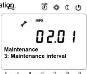
| 7044 | Maintenance interval | Months | 1 | 240 | |
| 7045 | Time since maintenance | Months | 0 | 240 | |
| 7050 | Fan speed ionization current | rpm | 0 | 10000 | |
| 7051 | Message ionization current | - | No, Yes | |
| 7130 | Chimney sweep function | - | Off, On | |
| 7131 | Burner output | - | Partial load, Full load, Max heating load | |
| 7140 | Manual control | - | Off, On | |
| 7143 | Controller stop function | - | Off, On | |
| 7145 | Controller stop setpoint | % | 0 | 100 | |
| 7146 | Deaeration function | - | Off, On | |
| 7147 Type of venting | - | None, Heating circuit continuous, Heating circuit cycled, DHW continuous, DHW cycled | |
| 7170 | Telephone customer service | - | 0 | 9 | |
| 7250 | PStick storage pos | - | 0 | 250 | |
| 7251 | PStick data description | - | 0 | 255 | |
| 7252 | PStick command | - | No operation, Reading from stick, Writing on stick | |
| 7253 | PStick progress | % | 0 | 100 | |
Parameters professional installer
| Menu | Line no. | Operating line | Unit | Min. Max | | Factory setting* |
| Service/Special operation | 7254 PStick status - | | No stickNo operationWriting on stickReading from stickEMC test activeWriting errorReading errorIncompatible data setWrong stick typeStick format errorCheck data setData set disabledReading disabled | |
| Input/Output Test | 7700 Relay test - | | No testEverything offRelay output QX1Relay output QX2Relay output QX3Relay output QX4Relay output QX21 module 1Relay output QX22 module 1Relay output QX23 module 1Relay output QX21 module 2Relay output QX22 module 2Relay output QX23 module 2Relay output QX21 module 3Relay output QX22 module 3Relay output QX23 module 3 | |
| 7713 | Output test P1 | % | 0 | 100 | |
| 7714 | PWM output P1 | % | 0 | 100 | |
| 7730 | Outside temp B9 | °C | -50 | 50 | |
| 7750 | DHW temp B3/B38 | °C | 0 | 140 | |
| 7760 | Boiler temp B2 | °C | 0 | 140 | |
| 7820 | Sensor temp BX1 | °C | -28 | 350 | |
| 7821 | Sensor temp BX2 | °C | -28 | 350 | |
| 7822 | Sensor temp BX3 | °C | -28 | 350 | |
| 7823 | Sensor temp BX4 | °C | -28 | 350 | |
| 7830 | Sensor temp BX21 module 1 | °C | -28 | 350 | |
| 7831 | Sensor temp BX22 module 1 | °C | -28 | 350 | |
| 7832 | Sensor temp BX21 module 2 | °C | -28 | 350 | |
| 7833 | Sensor temp BX22 module 2 | °C | -28 | 350 | |
| 7834 | Sensor temp BX21 module 3 | °C | -28 | 350 | |
| 7835 | Sensor temp BX22 module 3 | °C | -28 | 350 | |
| 7840 | Voltage signal H1 | V | 0 | 10 | |
| 7841 | Contact state H1 | - | Open, Closed | |
| 7845 | Voltage signal H2 module 1 | V | 0 | 10 | |
| 7846 | Contact state H2 module 1 | - | Open, Closed | |
| 7848 | Voltage signal H2 module 2 | V | 0 | 10 | |
| 7849 | Contact state H2 module 2 | - | Open, Closed | |
| 7851 | Voltage signal H2 module 3 | V | 0 | 10 | |
| 7852 | Contact state H2 module 3 | - | Open, Closed | |
| 7854 | Voltage signal H3 | V | 0 | 10 | |
| 7855 | Contact state H3 | - | Open, Closed | |
*See manual boiler
Parameters professional installer
| Menu | Line no. | Operating line | Unit | Min. | Max | Factory setting* |
| Input/Output Test | 7862 | Frequency H4 | - | 0 | 2000 | |
| 7860 | Contact state H4 | - | Open, Closed | |
| 7865 | Contact state H5 | - | Open, Closed | |
| 7872 | Contact state H6 | - | Open, Closed | |
| 7874 | Contact state H7 | - | Open, Closed | |
| 7950 | Input EX21 module 1 | - | 0V, 230V | |
| 7951 | Input EX21 module 2 | - | 0V, 230V | |
| 7952 | Input EX21 module 3 | - | 0V, 230V | |
| State | 8000 | State heating circuit 1 | - | 0: ---1: SLT tripped254: Value 550; 254255: Value 550; 255 | |
| 8001 | State heating circuit 2 | - | |
| 8002 | State heating circuit 3 | - | |
| 8003 | State DHW | - | |
| 8005 | State boiler | - | |
| 8007 | State solar | - | |
| 8008 | State solid fuel boiler | - | |
| 8009 | State burner | - | |
| 8010 | State buffer | - | |
| 8011 | State swimming pool | - | |
| Diagnostics cascade (when activated) | 8100 | Priority source 1 | - | 0 | 16 | Indication only |
| 8101 State source 1 - | | MissingFaultyManual control activeHeat generation lock activeChimney sweep funct activeTemporarily unavailableOutside temp limit activeNot releasedReleased |
| 8102 | Priority source 2 | - | 0 | 16 |
| 8103 | State source 2 | - | See Line no. 8101 |
| 8104 | Priority source 3 | - | 0 | 16 |
| 8105 | State source 3 | - | See Line no. 8101 |
| 8106 | Priority source 4 | - | 0 | 16 |
| 8107 | State source 4 | - | See Line no. 8101 |
| 8108 | Priority source 5 | - | 0 | 16 |
| 8109 | State source 5 | - | See Line no. 8101 |
| 8110 | Priority source 6 | - | 0 | 16 |
| 8111 | State source 6 | - | See Line no. 8101 |
| 8112 | Priority source 7 | - | 0 | 16 |
| 8113 | State source 7 | - | See Line no. 8101 |
| 8114 | Priority source 8 | - | 0 | 16 |
| 8115 | State source 8 | - | See Line no. 8101 |
| 8116 | Priority source 9 | - | 0 | 16 |
| 8117 | State source 9 | - | See Line no. 8101 |
| 8118 | Priority source 10 | - | 0 | 16 |
| 8119 | State source 10 | - | See Line no. 8101 |
| 8120 | Priority source 11 | - | 0 | 16 |
| 8121 | State source 11 | - | See Line no. 8101 |
| 8122 | Priority source 12 | - | 0 | 16 |
| 8123 | State source 12 | - | See Line no. 8101 |
| 8124 | Priority source 13 | - | 0 | 16 |
| 8125 | State source 13 | - | See Line no. 8101 |
*See manual boiler
| Menu | Line no. | Operating line | Unit | Min. Max | | Factory setting |
| Diagnostics Cascade | 8126 | Priority source 14 | - | 0 | 16 | Indication only |
| 8127 | State source 14 | - | See Line no. 8101 |
| 8128 | Priority source 15 | - | 0 | 16 |
| 8129 | State source 15 | - | See Line no. 8101 |
| 8130 | Priority source 16 | - | 0 | 16 |
| 8131 | State source 16 | - | See Line no. 8101 |
| 8138 | Cascade flow temp | °C | 0 | 140 |
| 8139 | Cascade flow temp setpoint | °C | 0 | 140 |
| 8140 | Cascade return temp | °C | 0 | 140 |
| 8141 | Cascade return temp | °C | 0 | 140 |
| 8150 | Source seq ch'over current | h | 0 | 990 |
| Diagnostics heat generation | 8304 | Boiler pump Q1 | - | Off, On | Indication only |
| 8308 | Boiler pump speed | % | 0 | 100 |
| 8310 | Boiler temp | °C | 0 | 140 |
| 8311 | Boiler setpoint | °C | 0 | 140 |
| 8312 | Boiler switching point | °C | 0 | 140 |
| 8313 | Inst heater switching point | °C | 0 | 140 |
| 8314 | Boiler return temp | °C | 0 | 140 |
| 8316 | Flue gas temp | °C | 0 | 350 |
| 8318 | Flue gas temp max | °C | 0 | 350 |
| 8321 | Primary exchanger temp | °C | 0 | 140 |
| 8323 | Fan speed | rpm | 0 | 8000 |
| 8324 | Setpoint fan | rpm | 0 | 8000 |
| 8325 | Current fan control | % | 0 | 100 |
| 8326 | Burner modulation | % | 0 | 100 |
| 8327 | Water pressure | - | 0 | 10 |
| 8329 | Ionization current | μA | 0 | 100 |
| 8330 | Hours run 1st stage | h | 00:00:00 | 2730:15:00 |
| 8331 | Start counter 1st stage | - | 0 | 2147483647 |
| 8338 | Hours run heating mode | h | 00:00:00 | 8333:07:00 |
| 8339 | Hours run DHW | h | 00:00:00 | 8333:07:00 |
| 8390 | Current phase number | - | 0: Value 777; 01: TNB254: Wert 777; 254255: Wert 777; 255 |
| 8499 | Collector pump 1 | - | Off, On |
| 8501 | Solar ctrl element buffer | - | Off, On |
| 8502 | Solar ctrl elem swimming | - | Off, On |
| 8505 | Speed collector pump 1 | % | 0 | 100 |
| 8506 | Speed solar pump ext exch | % | 0 | 100 |
Parameters professional installer
| Menu | Line no. | Operating line | Unit | Min. | Max | Factory setting |
| Diagnostics heat generation | 8507 | Speed solar pump buffer | % | 0 | 100 | Indication only |
| 8508 | Speed solar pump swi pool | % | 0 | 100 |
| 8510 | Collector temp 1 | °C | -28 | 350 |
| 8511 | Collector temp 1 max | °C | -28 | 350 |
| 8512 | Collector temp 1 min | °C | -28 | 350 |
| 8513 | dT collector 1/DHW | °C | -168 | 350 |
| 8514 | dT collector 1/buffer | °C | -168 | 350 |
| 8515 | dT collector 1/swimming pool | °C | -168 | 350 |
| 8519 | Solar flow temp | °C | -28 | 350 |
| 8520 | Solar return temp | °C | -28 | 350 |
| 8526 | 24-hour yield solar energy | kWh | 0 | 999,9 |
| 8527 | Total yield solar energy | kWh | 0 | 9999999,9 |
| 8530 | Hours run solar yield | h | 00:00:00 | 8333:07:00 |
| 8531 | Hours run collect overtemp | h | 00:00:00 | 8333:07:00 |
| 8532 | Hours run collector pump | h | 00:00:00 | 8333:07:00 |
| 8560 | Solid fuel boiler temp | °C | 0 | 140 |
| 8570 | Hours run solid fuel boiler | h | 00:00:00 | 8333:07:00 |
| Diagnostics consumers | 8700 | Outside temp | °C | -50 | 50 | Indication only |
| 8701 | Outside temp min | °C | -50 | 50 |
| 8702 | Outside temp max | °C | -50 | 50 |
| 8703 | Outside temp attenuated | °C | -50 | 50 |
| 8704 | Outside temp composite | °C | -50 | 50 |
| 8730 | Heating circuit pump 1 | - | Off, On |
| 8731 | Heat circ mix valve 1 open | - | Off, On |
| 8732 | Heat circ mix valve 1 close | - | Off, On |
| 8735 | Speed heating circuit pump 1 | % | 0 | 100 |
| 8740 | Room temp 1 | °C | 0 | 50 |
| 8741 | Room setpoint 1 | °C | 4 | 35 |
| 8743 | Flow temp 1 | °C | 0 | 140 |
| 8744 | Flow temp setpoint 1 | °C | 0 | 140 |
| 8749 | Room thermostat 1 | - | No demand, demand |
| 8760 | Heating circuit pump 2 | - | Off, On |
| 8761 | Heat circ mix valve 2 open | - | Off, On |
| 8762 | Heat circ mix valve 2 close | - | Off, On |
| 8765 | Speed heating circuit pump 2 | % | 0 | 100 |
| 8770 | Room temp 2 | °C | 0 | 50 |
| Diagnostics consumers | 8771 | Room setpoint 2 | °C | 4 | 35 | Indication only |
| 8773 | Flow temp 2 | °C | 0 | 140 |
| 8774 | Flow temp setpoint 2 | °C | 0 | 140 |
| 8779 | Room thermostat 2 | - | No demand, demand |
| 8790 | Heating circuit pump 3 | - | Off, On |
| 8791 | Heat circ mix valve 3 open | - | Off, On |
| 8792 | Heat circ mix valve 3 close | - | Off, On |
| 8795 | Speed heating circuit pump 3 | % | 0 | 100 |
| 8800 | Room temp 3 | °C | 0 | 50 |
| 8801 | Room setpoint 3 | °C | 4 | 35 |
| 8803 | Flow temp 3 | °C | 0 | 140 |
| 8804 | Flow temp setpoint 3 | °C | 0 | 140 |
| 8809 | Room thermostat 3 | - | No demand, demand |
| 8820 | DHW pump | - | Off, On |
| 8825 | Speed DHW pump | % | 0 | 100 |
| 8826 | Speed DHW interm circ pump | % | 0 100 | |
| 8827 | Speed inst DHW heater pump | % | 0 100 | |
| 8830 | DHW temp 1 | °C | 0 | 140 |
| 8831 | DHW temp setpoint | °C | 8 | 80 |
| 8832 | DHW temp 2 | °C | 0 | 140 |
| 8835 | DHW circulation temp | °C | 0 | 140 |
| 8836 | DHW charging temp | °C | 0 | 140 |
| 8852 | DHW consumption temp | °C | 0 | 140 |
| 8853 | Instant WH setpoint | °C | 0 | 140 |
| 8860 | DHW flow | l/min | 0 | 30 |
| 8875 | Flow temp setpoint VK1 | °C | 5 | 130 |
| 8885 | Flow temp setpoint VK2 | °C | 5 | 130 |
| 8895 | Flow temp setpoint VK3 | °C | 5 | 130 |
| 8900 | Swimming pool temp | °C | 0 | 140 |
| 8901 | Swimming pool setpoint | °C | 8 | 80 |
| 8930 | Primary controller temp | °C | 0 | 140 |
| 8931 | Primary controller setpoint | °C | 0 | 140 |
| 8950 | Common flow temp | °C | 0 | 140 |
| 8951 | Common flow temp setpoint | °C | 0 | 140 |
| 8952 | Common return temp | °C | 0 | 140 |
| Diagnostics consumers | 8962 | Common output setpoint | % | 0 | 100 | Indication only |
| 8980 | Buffer temp 1 | °C | 0 | 140 |
| 8981 | Buffer setpoint | °C | 0 | 140 |
| 8982 | Buffer temp 2 | °C | 0 | 140 |
| 8983 | Buffer temp 3 | °C | 0 | 140 |
| 9005 | Water pressure H1 | bar | 0 | 10 |
| 9006 | Water pressure H2 | bar | 0 | 10 |
| 9009 | Water pressure H3 | bar | 0 | 10 |
| 9031 | Relay output QX1 | - | Off, On |
| 9032 | Relay output QX2 | - | Off, On |
| 9033 | Relay output QX3 | - | Off, On |
| 9034 | Relay output QX4 | - | Off, On |
| 9050 | Relay output QX21 module 1 | - | Off, On |
| 9051 | Relay output QX22 module 1 | - | Off, On |
| 9052 | Relay output QX23 module 1 | - | Off, On |
| 9053 | Relay output QX21 module 2 | - | Off, On |
| 9054 | Relay output QX22 module 2 | - | Off, On |
| 9055 | Relay output QX23 module 2 | - | Off, On |
| 9056 | Relay output QX21 module 3 | - | Off, On |
| 9057 | Relay output QX22 module 3 | - | Off, On |
| 9058 | Relay output QX23 module 3 | - | Off, On |
| - | 2nd speed HC1 pump Q21 | - | Off, On | Indication only |
| - | Optg mode changeover HC1 | - | Inactive, Active |
| - | 2nd speed HC2 pump Q22 | - | Off, On |
| - | Optg mode changeover HC2 | - | Inactive, Active |
| - | 2nd speed HC2 pump Q23 | - | Off, On |
| - | Optg mode changeover HC3 | - | Inactive, Active |
| - | EI imm heater K6 | - | Off, On |
| - | Circulating pump Q4 | - | Off, On |
| - | Optg mode changeover DHW | - | Inactive, Active |
| - | H1 pump Q15 | - | Off, On |
| - | H2 pump Q18 | - | Off, On |
| - | H3 pump Q19 | - | Off, On |
| - | Prim contr/system pump Q14 | - | Off, On |
Parameters professional installer
| Menu | Line no. | Operating line | Unit | Min. | Max | Factory setting* |
|
| Diagnostics consumers | - | Precontroller mixing valve opens Y19 | - Off, On | Indication only |
| - | Precontroller mixing valve closes Y20 | - Off, On |
| - Heat generation lock Y4 - Off, On | |
| - | Time switch program 5 relais K13 | - Off, On |
| - Return temp valve Y15 - Off, On | |
| - Heat demand K27 - Off, On | |
| - | Instantaneous heater pump Q34 | - Off, On |
| - | Storage transfer pump Q11 | - Off, On |
| - DHW stirring pump Q35 - Off, On | |
| - | DHW intermediate circuit pump Q33 | - Off, On |
| - Flowswitch - Off, On | |
| Burner control | 9500 | Prepurge time | s | 0 | 51 | |
| 9512 | Required speed ignition | rpm | | 10000 | |
| 9524 | Required speed LF | rpm | 0 | 10000 | |
| 9529 | Required speed HF | rpm | 0 | 10000 | |
| 9540 | Postpurge time | s | 0 | 51 | |
| 9615 | Forced prepurging on error | - Off, On | |
| 9650 | Chimney drying | - | Off, Temporarily, Permanently | |
*See manual boiler
Manual control
Chimney sweeper function
Controller stop function
Various data can be displayed by pressing the info button.
Possible info
Depending on the type of unit, the configuration and operating state, some of the info lines listed below may not appear.
Manual control
When manual control is activated, the relays are no longer energized and deenergized according to the control status but are set to a predefined manual control status in accordance with their functions.
Boiler, Heating circuit, Transport and DHW pump are switched ON, Buffer pump is OFF.
The heating circuit mixer on the AVS75 controls to half of average value.
Setpoint adjustment in manual operation
After manual operation has been activated, a change to the basic display must be made where the service / special mode symbol appears:
The setpoint for manual control can be adjusted in the Boiler menu on parameter 2214.
Chimney sweep function
To start the chimney sweep function, press the button for a moment (<3 seconds). This function produces the operating state required to make emission measurements (flue gas).
Controller stop function
To start the chimney sweep function, hold the operation mode button for >3 seconds).
The controller stop function sets the burner to a fixed modulation. This function can be used to make emission measurements (flue gas).
To deactivate the function hold the operation mode button for >3 seconds.
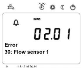
Error / Maintenance messages
In exceptional cases, the basic display shows one of the following symbols.

Error messages
If this symbol appears, an error in the plant occurred. Press the info button and read further information.

Maintenance/special operation
If this symbol appears, a maintenance alarm is delivered or the plant has changed to special mode. Press the info button and read further information.
List of display
Error codes
| Error code | Error description |
| 0 | No error |
| 10 | Outside temperature sensor error |
| 20 | Boiler temperature 1 sensor error |
| 26 | Common flow temperature sensor error |
| 28 | Flue gas temperature sensor error |
| 30 | Flow temperature 1 sensor error |
| 32 | Flow temperature 2 sensor error |
| 38 | Flow temperature primary controller sensor error |
| 40 | Return temperature 1 sensor error |
| 46 | Return temperature cascade sensor error |
| 47 | Common return temperature sensor error |
| 50 | DHW temperature 1 sensor error |
| 52 | DHW temperature 2 sensor error |
| 54 | DHW primary controller sensor error |
| 57 | DHW circulation temperature sensor error |
| 60 | Room temperature 1 sensor error |
| 65 | Room temperature 2 sensor error |
| 70 | Buffer storage tank temperature 1 sensor error |
| 71 | Buffer storage tank temperature 2 sensor error |
| 72 | Buffer storage tank temperature 3 sensor error |
| 73 | Collector temperature 1 sensor error |
| 74 | Collector temperature 2 sensor error |
| 82 | LPB address collision |
| 83 | BSB wire short-circuit |
| 84 | BSB address collision |
| 85 | BSB RF communication error |
| 91 | EEPROM error lockout information |
| 98 | Extension module 1 error (collective error) |
| 99 | Extension module 2 error (collective error) |
| 100 | 2 clocktime masters (LPB) |
List of display
Error codes
| Error code | Error description |
| 102 | Clocktime master without reserve (LPB) |
| 103 | Communication error |
| 105 | Maintenance message |
| 109 | Boiler temperature supervision |
| 110 | STB lockout |
| 111 | TW cutout |
| 121 | Flow temperature 1 (HC1) supervision |
| 122 | Flow temperature 2 (HC2) supervision |
| 125 | Pump supervision error |
| 126 | DHW charging supervision |
| 127 | Legionella temperature not reached |
| 128 | Loss of flame during operation |
| 129 | Fan error or LP error |
| 130 | Flue gas temperature limit exceeded |
| 131 | Burner fault |
| 132 | GP or LP error |
| 133 | No flame during safety time |
| 146 | Configuration error collective message |
| 151 | Internal error |
| 152 | Parameterization error |
| 153 | Unit manually locked |
| 160 | Fan error |
| 162 | LP error, does not close |
| 164 | Error heating circuit flow switch |
| 166 | LP error, does not open |
| 171 | Alarm contact H1 or H4 active |
| 172 | Alarm contact H2 (EM1, EM2 or EM3) or H5 active |
| 173 | Alarm contact H6 active |
| 174 | Alarm contact H3 or H7 active |
| 178 | Limit thermostat heating circuit 1 |
| 179 | Limit thermostat heating circuit 2 |
| 183 | Unit in parameterization mode |
| 193 | Pump supervision error after flame on |
| 216 | Fault boiler |
| 217 | Fault sensor |
| 241 | Flow sensor solar sensor error |
| 242 | Return sensor solar sensor error |
| 243 | Swimming pool temperature sensor error |
| 270 | Limit function |
| 317 | Mains frequency outside permissible range |
| 320 | DHW charging temperature sensor error |
| 324 | BX same sensors |
| 325 | BX / extension module same sensors |
| 326 | BX / mixing group same sensors |
| 327 | Extension module same function |
| 328 | Mixing group same finction |
| 329 | Extension module / mixing group same function |
List of display
Error codes
| Error code | Error description |
| 330 | Sensor BX1 no function |
| 331 | Sensor BX2 no function |
| 332 | Sensor BX3 no function |
| 333 | Sensor BX4 no function |
| 334 | Sensor BX5 no function |
| 335 | Sensor BX21 no function (EM1, EM2 or EM3) |
| 336 | Sensor BX22 no function (EM1, EM2 or EM3) |
| 337 | Sensor BX1 no function |
| 338 | Sensor BX12 no function |
| 339 | Collector pump Q5 not available |
| 340 | Collector pump Q16 not available |
| 341 | Solar Collector sensor B6 not available |
| 342 | DHW sensor B31 not available |
| 343 | Solar integration not available |
| 344 | Solar controlling element buffer K8 not available |
| 345 | Solar ctrl element swimming pool K18 not available |
| 346 | Solid fuel boiler pump Q10 not available |
| 347 | Solid fuel boiler comparison sensor not available |
| 348 | Solid fuel boiler address error |
| 349 | Buffer return valve Y15 not available |
| 350 | Puffer address sensor |
| 351 | Primary controller / system pump address error |
| 352 | Pressureless header address error |
| 353 | Common flow sensor B10 not available |
| 371 | Flow temperature 3 (heating circuit 3) supervision |
| 372 | Limit thermostat heating circuit 3 |
| 373 | Extension module 3 error (collective error) |
| 349 | Buffer return valve Y15 not available |
| 350 | Puffer address sensor |
| 351 | Primary controller / system pump address error |
| 352 | Pressureless header address error |
| 353 | Common flow sensor B10 not available |
| 371 | Flow temperature 3 (heating circuit 3) supervision |
| 372 | Limit thermostat heating circuit 3. |
| 373 | Extension module 3 error (collective error) |
| 386 | Fan speed has lost valid range |
| 388 | DHW error no function |
| 426 | Feedback flue gas damper |
| 427 | Configuration flue gas damper |
| 431 | Sensor primary heat exchanger |
| 432 | Functional earth not connected |
| 433 | Temperature primary heat exchanger to high |
Maintenance codes
| Maintenance code | Maintenance description |
| 1 | Burner hours run exceeded |
| 2 | Burner starts exceeded |
| 3 | Maintenance interval exceeded |
Detailed settings
Menu: time of day and date
Time of day and date
The controller has a yearly clock with time of day, weekday and date. To ensure the controller's functionality, both the time of day and the date must be correctly set.
Summer- / wintertime changeover
The dates set for the changeover from wintertime to summertime, and vice versa, ensure that on the first Sunday after the set date the time of day will change from 02:00 (wintertime) to 03:00 (summertime), and from 03:00 (summertime) to 02:00 (wintertime).
Line no. Operating line Factory setting
1 Hours / minutes
2 Day / month
3 Year
5 Start of summer time
6 End of summer time
See manual boiler
Operation and display
Language
Available languages vary depending on country and version.
Info
Temporarily:
After pressing the Info-button the Info display will appear. After 8 min. the basic display will reappear.
Permanently:
After activation the Info display will be shown permanently.
Operation lock
When operation lock is activated, the following operating elements can no longer be adjusted:
- Heating circuit operating mode
- DHW operating mode
- Room comfort setpoint (setting knob)
- Presence button
Programming lock
When programming lock is activated, parameter values can still be displayed, but can no longer be changed.
- Temporary deactivation of the programming lock
Within the programming level, the programming lock can temporarily be overridden. To do this, press the OK and ESC buttons simultaneously for 3 seconds. Temporary deactivation of the programming lock is maintained until programming is quit.
- Constant deactivation of programming lock
First, make the temporary deactivation, then go to operating line 27 Programming lock and deactivate the programming lock.
Direct adjustment
Automatic storage:
Altered values are stored without confirming with the OK-button.
| Line no. | Operating line Factory setting | |
| 20 | Language | See manual boiler |
| 22 | Info |
| Temporarily Permanently |
| 26 | Operation lock |
| 27 | Programming lock |
| 28 | Direct adjustment |
| 44 | Operation HC2 Jointly with HC1 Independently |
| 46 | Operation HC3/P Jointly with HC1 Independently |
| 70 | Software Version Indication only | |
Storage with confirmation:
Altered values are only stored after confirmation with the OK-button.
Operation HC2
Depending on operation line 40, the action of operation (operating mode button or rotary knob) on room unit 1, on the operator unit or service unit can be defined for HC2.
Jointly with HC1:
Operation acts commonly on HC1 and 2.
Independently:
The action of operation is queried on the display as soon as the operating mode button is pressed or the rotary knob is operated.
Operation HC3/P
Depending on operation line 40, the action of operation (operating mode button or rotary knob) on room unit 1, on the operator unit or service unit can be defined for HC3/P.
Jointly with HC1:
Operation acts commonly on HC1 and 2.
Independently:
The action of operation is queried on the display as soon as the operating mode button is pressed or the rotary knob is operated
Software version
The display shows the current version of the operator/room unit.
For the heating circuits and for DHW heating, a number of switching programs are available. They are activated in Automatic operation and control the change of the temperature levels (and the associated setpoints) via the selected switching times.
Entering the switching times
The switching times can be set in a combined way, that is, either jointly for several days or in the form of separate times for individual days. When preselecting groups of days like for instance Mo...Fr and Sa...Su that use the same switching times, the setting of switching programs is simplified.
Switching points
| Line no. | Operating line | Factory setting |
| HC1 | HC2 | 3/HC3 | 4/DHW | 5 |
| 500 | 520 | 540 | 560 | 600 | PreselectionMo - SuMo - FrSa - SuMo - Su | See manual boiler |
| 501 | 521 | 541 | 561 | 601 | 1. phase on |
| 502 | 522 | 542 | 562 | 602 | 1. phase off |
| 503 | 523 | 543 | 563 | 603 | 2. phase on |
| 504 | 524 | 544 | 564 | 604 | 2. phase off |
| 505 | 525 | 545 | 565 | 605 | 3. phase on |
| 506 | 526 | 546 | 566 | 606 | 3. phase off |
Standard program
All time programs can be reset to their default setting. Each time program hat its own operating line to make this reset.
| Line no. | Operating line | Factory setting |
| HC1 | HC2 | 3/HC3 | 4/DHW | 5 |
| 516 | 536 | 556 | 576 | 616 | Default values | See manual boiler |
Note: In that case, individual setting will be lost!
Holiday
The holiday program allows switching the operating level of the HCs according to date. On the last day heating is still deactivated. On the following day heating to comfort setpoint will commence according to the time program.
| Line no. Operating line Factory setting | |
| HC1 | HC2 | |
| 641 | 651 | PreselectionPeriod 1, 2, 3, 4, 5, 6, 7, 8 | See manual boiler |
| 642 | 652 | start |
| 643 | 653 | end |
| 648 | 658 | Operating levelFrost protectionReduced |
The holiday program can only be used in automatic mode.
For heating circuits, there are various functions available which can be individually set for each heating circuit.
Operating mode HCs
The operating modes of heating circuits are selected directly with the operating mode button. This setting is used to switch between different operating modes. Functionality corresponds to the operating mode selection via the operating mode button.
Protection
Continuous operation (24 hours) at the frost protection level. Switching program, occupancy button, holiday program, optimum start / stop control and ECO program have no impact. Control to room temperature frost protection can be deactivated. This may become necessary if a room thermostat is used for activating the boiler pump. In that case, it is only the room thermostat that prevents the room temperature from dropping. It should be considered however that when the flow temperature drops, the limit thermostat might cut out. The limit thermostat's cut-out temperature is 0 °C. This means that cutout must be prevented by appropriate setting of the room thermostat.
Automatic
Automatic operation at the Comfort, reduced or frost protection level in accordance with the switching program, the occupancy button, the holiday program, optimum start / stop control and the ECO function.
| Line no. Operating line Factory setting | |
| HC1 | HC2 | HC3 | |
| 700 | 1000 | Operating Mode HC Protection Automatic Reduced Comfort | See manual boiler |
Reduced
Continuous operation (24 hours) at the reduced level. Switching program, occupancy button, holiday program, optimum start / stop control and ECO program have no impact. The protective functions will remain active.
Comfort
Continuous operation (24 hours) at the Comfort level. Switching program, occupancy button, holiday program, optimum start / stop control and ECO program have no impact. The protective functions will remain active.
For heating circuits, there are various functions available which can be individually set for each heating circuit.
Room setpoint
Room temperature
The room temperature can be shifted according to different setpoints. These setpoints become active depending on the selected operating mode, thus producing different temperature levels in the rooms. The ranges of adjustable setpoints result from the interdependencies, as this is shown in the following diagram.
Frost protection
In protection mode, the room temperature is prevented from falling below a certain level. This means that the frost protection setpoint of the room temperature will be maintained.
| Line no. Operating line Factory setting | |
| HC1 HC2 | HC3 | |
| 710 1010 Comfortpoint | See manual boiler |
| 712 | 1012 | 1312 | Reduced setpoint |
| 714 | 1014 | 1314 | Frost protection |
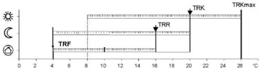
TRKmax Comfort setpoint maximum
TRK Comfort setpoint
TRR Reduced setpoint
TRF Frost protection setpoints
Heating curve
The heating curve is used to generate the flow temperature setpoint, which is used to maintain a certain flow temperature level depending on the prevailing weather conditions.
The heating curve can be adjusted with a number of setting, thus matching heat output and room temperature to individual needs.
Heating curve slope
As the heating curve slope is raised, the flow temperature increases quicker at lower outside temperature. In other words, if the room temperature is not correct at low outside temperatures but correct at higher outside temperatures, the heating curve slope requires readjustment.
Increase adjustment:
Raises the flow temperature, especially when outside temperatures are low.
Decrease adjustment:
Lowers the flow temperature, especially when outside temperatures are low.
| Line no. Operating line Factory setting | |
| HC1 HC2 HC3 | | |
| 720 - - Heating curve slope | See manual boiler |
| - 1020 - Heating curve slope |
| - | - | 1320 | Heating curve slope |
| 721 | 1021 | 1321 | Heating curve displacement |
| 726 | 1026 | 1326 | Heating curve adaption |
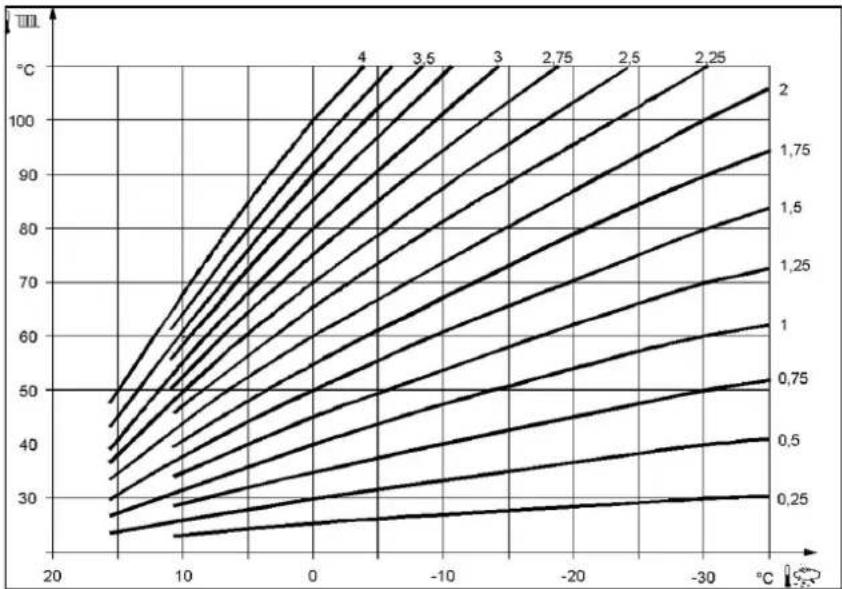
line
| Temperature (°C) | Value 1 | Value 2 | Value 3 | Value 4 |
| ---------------- | ------- | ------- | ------- | ------- |
| 20 | 25 | 30 | 35 | 40 |
| 10 | 30 | 35 | 40 | 45 |
| 0 | 35 | 40 | 45 | 50 |
| -10 | 40 | 45 | 50 | 55 |
| -20 | 45 | 50 | 55 | 60 |
| -30 | 50 | 55 | 60 | 65 |
| -40 | 55 | 60 | 65 | 70 |
| -50 | 60 | 65 | 70 | 75 |
| -60 | 65 | 70 | 75 | 80 |
| -70 | 70 | 75 | 80 | 85 |
| -80 | 75 | 80 | 85 | 90 |
| -90 | 80 | 85 | 90 | 95 |
| -100 | 85 | 90 | 95 | 100 |
| -110 | 90 | 95 | 100 | 105 |
| -120 | 95 | 100 | 105 | 110 |
| -130 | 100 | 105 | 110 | 115 |
| -140 | 105 | 110 | 115 | 120 |
| -150 | 110 | 115 | 120 | 125 |
| -160 | 115 | 120 | 125 | 130 |
| -170 | 120 | 125 | 130 | 135 |
| -180 | 125 | 130 | 135 | 140 |
| -190 | 130 | 135 | 140 | 145 |
| -200 | 135 | 140 | 145 | 150 |
| -210 | 140 | 145 | 150 | 155 |
| -220 | 145 | 150 | 155 | 160 |
| -230 | 150 | 155 | 160 | 165 |
| -240 | 155 | 160 | 165 | 170 |
| -250 | 160 | 165 | 170 | 175 |
| -260 | 165 | 170 | 175 | 180 |
| -270 | 170 | 175 | 180 | 185 |
| -280 | 175 | 180 | 185 | 190 |
| -290 | 180 | 185 | 190 | 195 |
| -300 | 185 | 190 | 195 | 200 |
| -310 | 190 | 195 | 200 | 205 |
| -320 | 195 | 200 | 205 | 210 |
| -330 | 200 | 205 | 210 | 215 |
| -340 | 205 | 210 | 215 | 220 |
| -350 | 210 | 215 | 220 | 225 |
| -360 | 215 | 220 | 225 | 230 |
| -370 | 220 | 225 | 230 | 235 |
| -380 | 225 | 230 | 235 | 240 |
| -390 | 230 | 235 | 240 | 245 |
| -400 | 235 | 240 | 245 | 250 |
| -410 | 240 | 245 | 250 | 255 |
| -420 | 245 | 250 | 255 | 260 |
| -430 | 250 | 255 | 260 | 265 |
| -440 | 255 | 260 | 265 | 270 |
| -450 | 260 | 265 | 270 | 275 |
| -460 | 265 | 270 | 275 | 280 |
| -470 | 270 | 275 | 280 | 285 |
| -480 | 275 | 280 | 285 | 290 |
| -490 | 280 | 285 | 290 | 295 |
| -500 | 285 | 290 | 295 | 300 |
| -510 | 290 | 295 | 300 | 305 |
| -520 | 295 | 300 | 305 | 310 |
| -530 | 300 | 305 | 310 | 315 |
| -540 | 305 | 310 | 315 | 320 |
| -550 | 310 | 315 | 320 | 325 |
| -560 | 315 | 320 | 325 | 330 |
| -570 | 320 | 325 | 330 | 335 |
| -580 | 325 | 330 | 335 | 340 |
| -590 | 330 | 335 | 340 | 345 |
| -600 | 335 | 340 | 345 | 350 |
| -610 | 340 | 345 | 350 | 355 |
| -620 | 345 | 350 | 355 | 360 |
| -630 | 350 | 355 | 360 | 365 |
| -640 | 355 | 360 | 365 | 370 |
| -650 | 360 | 365 | 370 | 375 |
| -660 | 365 | 370 | 375 | 380 |
| -670 | 370 | 375 | 380 | 385 |
| -680 | 375 | 380 | 385 | 390 |
| -690 | 380 | 385 | 390 | 395 |
| -700 | 385 | 390 | 395 | >4. The chart displays a line graph with x-axis labeled 'Temperature (°C)' and y-axis labeled 'Value' (in °C). The legend indicates 'Value' for each curve. The data series are labeled numerically from '4' to 'N'. The chart is saved as a PNG file named 'chart.png'.
Heating curve displacement
Parallel displacement of the heating curve is used to change the flow temperature evenly across the entire outside temperature range. In other words, if the room temperature is always too high or too low, a readjustment must be made with the help of the parallel displacement.
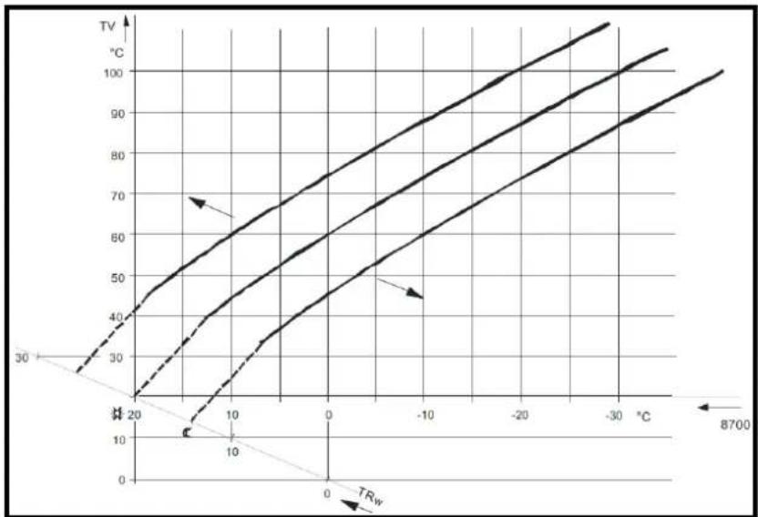
line
| Temperature (°C) | TV (°C) - Curve 1 | TV (°C) - Curve 2 | TV (°C) - Curve 3 |
| ---------------- | ----------------- | ----------------- | ----------------- |
| 0 | 30 | 40 | 50 |
| 10 | 40 | 60 | 70 |
| 20 | 50 | 70 | 80 |
| 30 | 60 | 80 | 90 |
| 40 | 70 | 90 | 100 |
| 50 | 80 | 100 | 110 |
| 60 | 90 | 110 | 120 |
| 70 | 100 | 120 | 130 |
| 8700 | - | - | - |
| Line no. Meaning | |
| 8700 TA Readjustm outside |
| TRw Room temp setpoint |
| TV Flow temp | |
Heating curve adaption
Adaption of the heating curve is used by the controller to automatically adapt the heating curve to the prevailing conditions. In that case, a readjustment of heating curve slope and parallel displacement is not required. It can only be switched on or off.
To assure this function, following must be observed:
• A room sensor must be connected
• The Room influence setting must be selected between 1 and 99
- There should be no thermostatic radiator valves in the reference room (mounting location of room sensor) (if such valves are present, they must be set to their fully open position).
ECO-Function
Summer/winter heating limit
The summer / winter heating limit is used to switch the heating on and off in the course of the year, depending on temperature conditions. In automatic mode, switching on / off takes place automatically, so there is not need for the user to do this manually. By changing the setting, the respective periods of time will be shortened or extended.
Increase:
Winter operation will start earlier. Summer operation will start later.
Decrease:
Winter operation will start later.
Summer operation will start earlier.
- The function is not active in operating mode Comfort
• The display shows ECO
- To incorporate the building's thermal dynamics, the outside temperature is attenuated
| Line no. Operating line Factory setting | |
| HC1 HC2 HC3 | |
| 730 | 1030 | 1330 | Summer/winter heating limit | See manual boiler |
| 732 | 1032 | 1332 | 24-hour heating limit |
| 733 | 1033 | 1333 | Ext'n 24-hour heating limit |
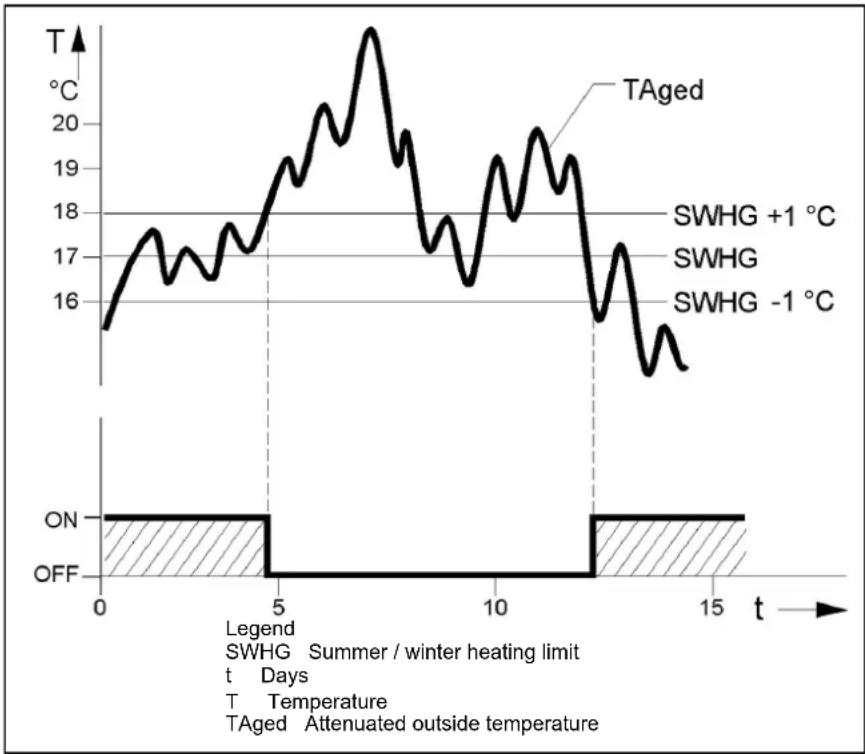
line
| Time (t) | Temperature (°C) |
| -------- | ---------------- |
| 0 | 16 |
| 5 | 18 |
| 10 | 19 |
| 15 | 15 |
24-hour heating limit
The 24-hour heating limit is used to switch the heating on and off in the course of the day, depending on the outside temperature. This function is used primarily during spring and autumn to respond to short-term temperature variations.
By changing the value entered, the respective heating periods will be shortened or extended.
Increase: Heating mode will start earlier. Changeover to ECO later.
Decrease: Heating mode will start later.
Changeover to ECO earlier.
- The function is not active in operating mode Continuously comfort temperature.
• The display shows ECO
- To give consideration to the building's thermal dynamics, the outside temperature will be attenuated.
Example
| Setting line E.g. | |
| Comfort setpoint (TRw) | 22°C |
| 24-hour heating limit (THG) | -3°C |
| Changeover temperature (TRw-THG) heating OFF | = 19°C |
| Switching differential (fixed) | -1°C |
| Changeover temperature heating ON | = 18°C |
Ext'n 24-hour heating limit
The 24-hour heating limit is extended by giving consideration to the composite outside temperature when the heating is switched on. Alternatively, the heating can be switched on again only dependent on the current outside temperature.
No
The 24-hour heating limit applies only dependent on the current outside temperature.
Yes
The 24-hour heating limit applies as described under 24-hour heating limit, depending on both the current and the composite outside temperature.
Flow temp setpoint min/ max
Using this limitation, a temperature range for the flow temperature setpoint can be defined. If the flow temperature setpoint demanded by the heating circuit reaches the relevant limit and the heat request increases or decreases, the flow temperature setpoint will be maintained at the maximum or minimum limit.
| Line no. Operating line Factory setting | |
| HC1 HC2 HC3 |
| 740 | 1040 | 1340 | Flow temp setpoint min | See manual boiler |
| 741 - | - Flow temp setpoint max HC1 |
| - 1041 - Flow temp setpoint max HC2 |
| - - 1341 Flow temp setpoint max HC3 |
| 742 - | - Flow temp setpoint room stat HC1 |
| - 1042 - Flow temp setpoint room stat HC2 |
| - - 1342 Flow temp setpoint room stat HC3 |
| 746 | 1046 | 1346 | Delay heat request |
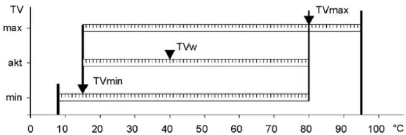
line
| Temperature (°C) | Voltage Level | Label |
|---|---|---|
| 10 | min | |
| 15 | max | |
| 80 | max | TVmax |
| 80 | akt | |
| 40 | max | |
| 40 | akt | TVw |
| 95 | max | |
Legend
TVw Current flow temperature setpoint
TVmax Flow temperature setpoint maximum
TVmin Flow temperature setpoint minimum
Room influence
Type of compensation
When a room temperature sensor is used, there is a choice of 3 different types of compensation.
| Line no. | Operating line | Factory setting |
| HC1 | HC2 | HC3 |
| 750 | 1050 | 1350 | Room influence | See manual boiler |
| Setting | Type of compensation |
| - - - % | Pure weather compensation * |
| 1...99 % | Weather compensation with room influence * |
| 100 % | Pure room compensation |
Pure weather compensation
The flow temperature is calculated via the heating curve, depending on the composite outside temperature. This type of compensation calls for a correct adjustment of the heating curve since in this case the control gives no consideration to the room temperature.
Weather compensation with room influence
Deviations of the actual room temperature from the setpoint are acquired and taken into account when controlling the temperature. Heat gains can thus be considered, facilitating more accurate room temperature control. The authority of deviation is set as a percentage figure. The better the reference room (correct room temperature, correct mounting location, etc.) the higher the value can be set.
* Outside sensor required.
To activate the function, following must be considered:
- A room sensor must be connected
• Room influence must be set to a value between 1 and 99 %
- There should be no thermostatic radiator valves in the reference room (mounting location of the room sensor) (if such valves are present, they must be set to their fully open position).
Example:
Approx. 60 % Good reference room conditions
Approx. 20 % Unfavorable reference room
Pure room compensation
The flow temperature is controlled depending on the room temperature setpoint, the current room temperature and the progression of the room temperature. For example, a slight increase of the room temperature causes an immediate drop of the following temperature.
To activate the function, following must be considered:
• A room sensor must be connected
• Room influence must be set to 100 %
- There should be no thermostatic radiator valves in the reference room (mounting location of the room sensor) (if such valves are present, they must be set to their fully open position)
Room temperature control and limitation
With the room temperature limitation function, the heating circuit pump can be disabled if the room temperature exceeds the current room temperature setpoint by more than the preset differential.
The room temperature limitation does not work in the case of pure weather compensation.
| Line no. Operating line Factory setting | |
| HC1 | HC2 | HC3 | | |
| 760 | 1 | 060 | Room 1860 limitation | See manual boiler |
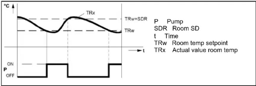
line
| Time | TRx | TRw | TRw+SDR |
|------|-----|-----|---------|
| t | ON | OFF | ON |
| t | OFF | OFF | OFF |
Boost heating
Boost heating is used to reach the new setpoint more quickly when switching from the reduced setpoint to the comfort setpoint, thus reducing the heat-up time. During boost heating, the room temperature setpoint is raised by the value set here. A higher setting leads to shorter heat-up times, a lower setting to longer heat-times.
Boost heating is possible with or without room sensor.
| Line no. Operating line Factory setting | |
| HC1 | HC2 | HC3 | |
| 770 | 1070 | 1370 | Boost heating | See manual boiler |
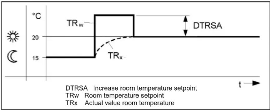
line
| Time | Temperature (°C) |
|------|------------------|
| 0 | 15 |
| 20 | 20 |
| 30 | 15 |
| 40 | 15 |
| 50 | 15 |
| 60 | 15 |
| 70 | 15 |
| 80 | 15 |
| 90 | 15 |
| 100 | 15 |
| 110 | 15 |
| 120 | 15 |
| 130 | 15 |
| 140 | 15 |
| 150 | 15 |
| 160 | 15 |
| 170 | 15 |
| 180 | 15 |
| 190 | 15 |
| 200 | 15 |
| 210 | 15 |
| 220 | 15 |
| 230 | 15 |
| 240 | 15 |
| 250 | 15 |
| 260 | 15 |
| 270 | 15 |
| 280 | 15 |
| 290 | 15 |
| 300 | 15 |
| 310 | 15 |
| 320 | 15 |
| 330 | 15 |
| 340 | 15 |
| 350 | 15 |
| 360 | 15 |
| 370 | 15 |
| 380 | 15 |
| 390 | 15 |
| 400 | 15 |
| 410 | 15 |
| 420 | 15 |
| 430 | 15 |
| 440 | 15 |
| 450 | 15 |
| 460 | 15 |
| 470 | 15 |
| 480 | 15 |
| 490 | 15 |
| 500 | 15 |
| 510 | 15 |
| 520 | 15 |
| 530 | 15 |
| 540 | 15 |
| 550 | 15 |
| 560 | 15 |
| 570 | 15 |
| 580 | 15 |
| 590 | 15 |
| 600 | 15 |
| 610 | 15 |
| 620 | 15 |
| 630 | 15 |
| 640 | 15 |
| 650 | 15 |
| 660 | 15 |
| 670 | 15 |
| 680 | 15 |
| 690 | 15 |
| 700 | 15 |
| 710 | 15 |
| 720 | 15 |
| 730 | 15 |
| 740 | 15 |
| 750 | 15 |
| 760 | 15 |
| 770 | 15 |
| 780 | 15 |
| 790 | 15 |
| 800 | - |
| TDRSA Increase Room Temperature Setpoint; TRw Room temperature Setpoint; TRx Actual value Room temperature; DTRSA Increase Room Temperature Setpoint; DTRSA Room temperature Setpoint; DTRx Actual value Room temperature; t → End of curve; t → Start of curve; t → End of curve.
Quick setback
During quick setback, the heating circuit pump is deactivated and, in the case of mixing valve circuits, the mixing valve is fully closed.
Function with room sensor:
- When using the room sensor, the function keeps the heating switched off until the room temperature has dropped to the level of the reduced setpoint or the frost level. When the room temperature has fallen to the reduced level or the frost level, the heating circuit pump will be activated and the mixing valve will be released.
- Function without room sensor: Quick setback switches the heating off for a certain period of time, depending on the outside temperature and the building time constant.
- Quick setback is possible with or without a room sensor.
| Line no. | Operating line | Factory setting |
| HC1 HC2 HC3 | |
| 780 | 1080 | 1380 | Quick setbackOffDown to reduced setpointDown to frost prot setpoint | See manual boiler |
Example:
Duration of quick setback when comfort setpoint minus reduced setpoint = 2 °C (e.g. comfort setpoint = 20 °C and reduced setpoint = 18 °C)
| Outside temp composite | Time constant building (Line no. 6110) |
| 0 | 2 | 5 | 10 | 15 | 20 | 50 |
| 15 °C | 0 | 3.1 | 7.7 | 15.3 | 23 | 30.6 | 76.6 |
| 10 °C | 0 | 1.3 | 3.3 | 6.7 | 10 | 13.4 | 33.5 |
| 5 °C | 0 | 0.9 | 2.1 | 4.3 | 6.4 | 8.6 | 21.5 |
| 0 °C | Frost protection |
| Duration of quick setback in hours |
When differential between Comfort setpoint and reduced setpoint is f.e. 4^ C, the default values in the table will be doubled.
Optimum start / stop control
Optimum start control max
The change from one temperature level to the other is optimized in a way that the comfort setpoint is reached at the relevant switching time.
Optimum stop control max
The change from one temperature level to the other is optimized in a way that the comfort setpoint minus 14 °C is reached at the relevant switching time.
- Optimum start / stop control is possible with or without room sensor.
| Line no. Operating line Factory setting | |
| HC1 H | C2 HC3 | | |
| 790 | 1090 | 1390 | Optimum start control max | See manual boiler |
| 791 | 1091 | 1391 | Optimum stop control max |
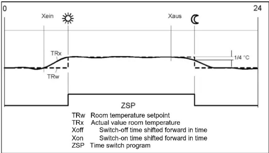
Raising the reduced setpoint
The function is used primarily in connection with heating systems with only little spare capacity (e.g. low-energy houses).
In such cases, the heating up time would be too long at low outside temperatures. When the reduced setpoint is raised, the rooms are prevented from cooling down to too low levels, thus shortening the heating up time when changing to the comfort setpoint.
| Line no. Operating line Factory setting | |
| HC1 HC2 HC3 | | |
| 800 | 1100 | 1400 | Reduced setp increase start | See manual boiler |
| 801 | 1101 | 1401 | Reduced setp increase end |
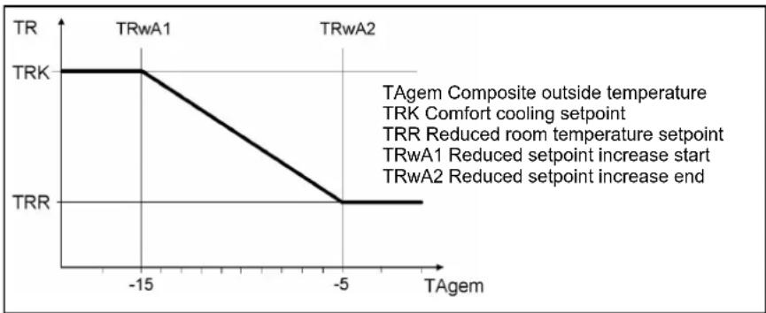
line
| Temperature | Phase |
| :--- | :--- |
| -15 | TRW1 |
| -5 | TRW2 |
| -15 | TRK |
| -5 | TRR |
TAgem Composite outside temperature
TRK Comfort cooling setpoint
TRR Reduced room temperature setpoint
TRwA1 Reduced setpoint increase start
TRwA2 Reduced setpoint increase end
Overtemperature protection
Overtemperature protection for pump heating circuit
In the case of heating plant with pump heating circuits, the flow temperature of the heating circuit can be higher than the flow temperature demanded by the heating curve, due to requests from other heat consumers (mixing heating circuit, DHW charging, external heat demand), or a parameterized minimum boiler temperature.
| Line no. | Operating line | Factory setting |
| HC1 | HC2 | HC3 |
| 820 | 1120 | 1420 | Overtemperature protection forPump heating circuitOffOn | See manual boiler |
As a result of this too high flow temperature, the pump heating circuit would assume excessive temperatures. The function overtemperature protection for pump heating circuits ensures that the energy supply for pump heating circuits corresponds to the demand from the heating curve by activating / deactivating the pump.
The cycling period is fixed at 10 min. This period of time is broken down according to a time ration. The pump's running time is set to a minimum of 3 minutes. The pump's off time is set to a minimum of 2 minutes.
Mixing valve control
Mixing valve boost
To ensure proper mixing valve flow temperature control, the flow temperature must be higher than the demanded setpoint of the mixing valve flow temperature. The value set here is added to the request.
The selection of the type of actuator determines the control behavior for the type of mixing valve actuator used.
| Line no. Operating line Factory setting | |
| HC1 H | C2 HC3 | | |
| 830 | 1130 | 1430 | Mixing valve boost | See manual boiler |
| 832 | 1132 | 1432 | Actuator typ Position-2 Position-3 |
| 833 | 1133 | 1433 | Switching differential 2-pos |
| 834 | 1134 | 1434 | Actuator running time |
| 835 | 1135 | 1435 | Mixing valve Xp |
| 836 | 1136 | 1436 | Mixing valve Tn |
2-position
The controller drives the actuator with only one relay output. When the output delivers a signal, the valve opens. If the signal is missing, the valve will automatically close (thermally or mechanically).
If the flow temperature lies more than half the switching differential below the setpoint, relay "Mixing valve opening" will be energized and remains energized until the flow temperature exceeds the setpoint by half the switching differential.
3-position
The controller drives the actuator with 2 relay outputs. One of the outputs is used for opening the valve and one for closing the valve. If none of the relays is energized, the actuator maintains its position.
Control is accomplished with a PID controller, whereby XP and TN can be parameterized. The actuator running time can also be set. The controller's neutral zone is +/- 1K. In the case of difficult controlled systems, the control parameters can be matched to the system.
Switching differential 2-pos
For the 2-position actuator, the 2-position switching differential must also be adapted. This is not required when using a 3-position actuator.
Actuator running time
Setting the running time of the actuator used with the mixing valve.
Mixing valve Xp
The mixing valve's P-band can be adjusted, thereby matching the control behavior of the vale's actuator to that of the plant (controlled system). Xp influences the controller's P-behavior.
Mixing valve Tn
The mixing valve's integral action time can be adjusted, thereby matching the control behavior of the vale's actuator to that of the plant (controlled system). Tn influences the controller's l-behavior.
Floor curing function
The floor curing function ensures controlled drying of the floor. It controls the flow temperature according to a temperature profile. Drying of the floor is ensured via the floor heating system and the mixing or pump heating circuit.
Floor curing function
Off
Function is deactivated.
Functional heating
The first part of the temperature profile is automatically completed.
Curing heating
The second part of the temperature profile is traversed automatically.
Functional/curing heating
The entire temperature profile (first and second part) is passed automatically.
Manually
It is not a temperature profile that is completed, but the floor setpoint is controlled manually.
Floor curing setp manually
The flow temperature setpoint for the manual floor-curing function can be set separately for each heating circuit.
Floor curing setp current
Shows the current flow temperature setpoint while the floor-curing function is in progress.
Floor curing day current
Shows the current weekday of the floor-curing function in progress.
| Line no. Operating line Factory setting | |
| HC1 HC2 HC3 | | |
| 850 | 1150 | 1450 | Floor curing functionOffFunctional heatingCuring heatingFunctional/curing heatingManually | See manual boiler |
| 851 | 1151 | 1451 | Floor curing setp manually |
| 855 | 1155 | 1455 | Floor curing setp current |
| 856 | 1156 | 1456 | Floor curing day current |
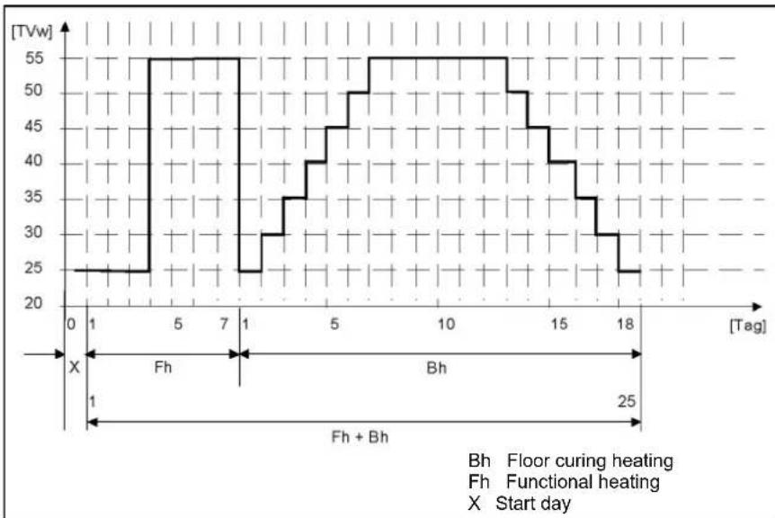
line
| [Tag] | Temperature (TVw) |
|-------|-------------------|
| 0 | 25 |
| 1 | 25 |
| 5 | 55 |
| 7 | 55 |
| 1 | 25 |
| 1 | 30 |
| 5 | 40 |
| 7 | 50 |
| 10 | 55 |
| 12 | 55 |
| 15 | 45 |
| 17 | 35 |
| 18 | 25 |
- Observe the relevant standards and regulations of the floor manufacturer
- Proper functioning is ensured only when the plant is correctly installed (hydraulic
system, electrical installation, setting)! If not observed, the floor might get damaged
- The function can be aborted by choosing Off
• Maximum limitation of the flow temperature remains active
Excess heat draw
Excess heat draw can be triggered by the following functions:
- Inputs Hx
- Storage tank recooling
- Solit fuel boiler excess heat draw
When dissipation of excess heat is activated, it can be draw by space heating. This can be adjusted separately for each heating circuit.
Off
Excess heat draw is deactivated.
Heating mode
Excess heat is drawn only when the controller operates in heating mode.
Always
Excess heat is drawn in all operating modes.
| Line no. Operating line Factory setting | |
| HC1 | HC2 | HC3 | | |
| 861 | 1 | 161 | Excess46at | drawOffHeating modealways | See manual boiler |
With buffer
If there is a buffer storage tank, specify whether the heating circuit can draw heat from it. When using alternative heat sources, the buffer storage tak temperature is used as a control criteria for the release of additional heat sources.
| Line no. Operating line | Factory setting |
| HC1 | HC2 | HC3 | |
| 870 | 1170 | 1470 | With bufferNoYes | See manual boiler |
| 872 | 1172 | 1472 | With prim/contr system pumpNoYes |
With prim/contr system pump
Specify whether the heating circuit receives its heat via the primary controller or with the help of the system pump (depending on the type of plant).
Flow setp readj speed ctrl
Here, it can be determined whether or not the calculated readjustment of the flow temperature setpoint shall be included in the temperature request.
| Line no. Operating line Factory setting | |
| HC1 HC2 HC3 | | |
| 890 | 1190 | 1490 | Flow setp readj speed ctrlNoYes | See manual boiler |
Remote control
Operating level changeover
The operating level to which the heating circuits shall be switched can be selected via an external time switch and inputs Hx.
Optg mode changeover
The heating circuit can be forced to adopt a selected mode via the H input by operating a contact. The operating mode required when the changeover is made can be defined in the “Operating mode changeover” parameters for each heating circuit. In that case, selection of the operating modes on the controller is locked.
| Line no. Operating line Factory setting | |
| HC1 | HC2 | HC3 | |
| 898 | 1198 | 1498 | Operating level changeoverFrost protectionReducedcomfort | See manual boiler |
| 900 | 1200 | 1500 | Optg mode changeoverNoneProtectionReducedComfortAutomatic |
Operating mode
The DHW operating mode is operated directly via operating button.
Off
Continuous operation, the setpoint being the DHW frost protection setpoint (5 °C).
On
DHW charging takes place automatically, the setpoint being the nominal DHW setpoint or the reduced DHW setpoint based on the selected kind of DHW release.
| Line no. | Operating line Factory setting | |
| 1600 | Operating modeOffOn | See manual boiler |
Setpoints
The DHW setpoint acting on the control is selected based on the current operating level which includes impact of the operating mode, the release (possibly the switching program), the DHW push and the0 legionella function.
Nominal setpoint
Backup temperature inside the release.
Reduced setpoint
Backup temperature outside the release.
| Line no. Operating line Factory setting | |
| 1610 Nominal setpoint | See manual boiler |
| 1612 Reduced setpoint |
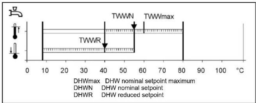
| Line no. | Operating line | Factory setting |
| 1620 Release24h/dayTime programs HCsTime program 4/D HW | See manual boiler |
24h/Day
When this setting is used, DHW heating is continuously released as long as it is switched on. The DHW setpoint is always the nominal setpoint, unless the legionella function has been activated.
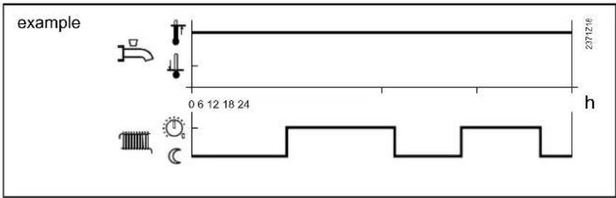
Time programs HCs
When this setting is used, DHW heating is released during the occupancy times of the connected heating circuits. If at least one of the heating circuits is at the Comfort level, DHW heating will also be released. If all heating circuits are at the reduced level or in protective mode, the DHW level will also be set to reduced.
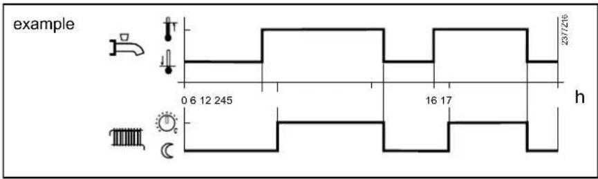
Time program 4/DHW
When using this setting, a specific time program is available for DHW heating. For every weekday, a time program with a maximum of three on phases can be set. During the release time, the nominal DHW setpoint applies, outside the release time, the reduced DHW setpoint. If the legionella function is pending, it will be performed when DHW heating is released for the first time in the morning. Setting "Once / several times per day" has no impact. If DHW heating is switched off, the frost protection setpoint will apply.
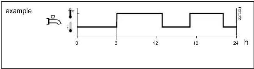
line
| h | value |
| --- | ----- |
| 0 | 23/3224 |
| 6 | 23/3224 |
| 18 | 23/3224 |
| 24 | 23/3224 |
Charging priority
When both space heating and DHW heating call for heat, the DHW priority function ensures that while DHW charging is in progress, the boiler's capacity is used primarily for DHW heating.
| Line no. | Operating line | Factory setting |
| 1630 | Charging priorityAbsoluteShiftingNoneMC shifting, PC absolute | See manual boiler |
With diverting valves, the function is automatically deactivated.
Absolute
The mixing and pump heating circuits stay locked until DHW heating is completed.
Shifting
If the capacity of the heat source is not sufficient, the mixing and pump heating circuits will be restricted until DHW is heated up.
None
DHW heating and space heating take place at the same time. In the case of tightly sized boilers and mixing heating circuits,
the DHW setpoint may not be reached if space heating demands considerable amounts of heat.
MC shifting, PC absolute
The pump heating circuits stay locked until the DHW storage tank is heated up. If the capacity of the heat source is not sufficient, the mixing heating circuits will be restricted also.
Legionella function
Off
The function is deactivated.
Periodically
The legionella function is repeated according to the interval set (operating line 1641). The legionella setpoint is attained via a solar plant, independent of the period of time set, the period of time will be newly started. This means that the heat source is switched on only if the solar plant could not deliver the required “Legionella function setpoint” within the adjusted period of time.
Fixed weekday
The legionella function can be activated on a fixed weekday (operating line 1642). When using this setting, heating up to the legionella setpoint takes place on the selected weekday, independent of previous storage tank temperatures. This setting is intended primarily for plant with no solar integration.
Legionella funct periodically
Setting “Legionella funct periodically” is used to select after how many weekdays the function shall be activated again. (This setting is active only if parameter “Legionella function” is set to “Periodically”).
Legionella funct weekday
Parameter “Legionella funct weekday” is used to select on which weekday the function shall be performed. The function is carried out on the selected weekday, independent of the availability of alternative energy.
Legionella function time
The legionella function is started at the time set. The DHW setpoint is raised to the adjusted legionella setpoint and DHW charging is started.
If no time is parameterized, the legionella function is started on the respective day together with the first normal release of DHW heating. If no release of DHW heating is scheduled for that day (continuously reduced), the legionella function will be performed at 24:00.
| Line no. Operating line Factory setting | |
| 1640 Legionella functionOffPeriodicallyFixed weekday | See manual boiler |
| 1641 Legionella funct periodically |
| 1642 Legionella funct weekdayMo - Su |
| 1644 Legionella function time |
| 1645 Legionella funct setpoint |
| 1646 Legionella funct duration |
| 1647 Legionella funct. circ. pumpOffOn |
If DHW heating is switched off (DHW operating mode button = off or holidays), the legionella function will be made up for as soon as DHW heating is switched on again (DHW operating mode button = on or end of holiday period).
Legionella funct setpoint
The higher the temperature level of the storage tank, the shorter the required dwelling time at that level.
Legionella funct duration
The demanded “Legionella function setpoint” must be continuously maintained during the dwelling time set. If the storage tank temperature (in the case of 2 sensors, the temperature acquired by the “colder” sensor) exceeds the “Legionella function setpoint” minus 1 K, the “Legionella function setpoint” is considered fulfilled and the “Dwelling time” timer elapses. If the storage tank temperature drops below the demanded “Legionella function setpoint” by more than the switching differential plus 2 K before the dwelling time has elapsed, the dwelling time must be fulfilled again. If no dwelling time is set, the “Legionella” function is performed the moment the “Legionella function setpoint” is reached.
If the "Legionella" function cannot be performed within a 48-hour period, an error message will be delivered.
Legionella funct circ pump
When the function is activated, the circulating pump is switched on while the "Legionella" function is performed as soon as the storage tank temperature (in the case of 2 sensors the temperature acquired by the "colder" sensor) lies above the "Legionella function setpoint" minus 1 K. The pump runs during the dwelling time set. If the storage tank temperature falls below the demanded "Legionella function setpoint" by more than the DHW switching differential plus 2 K, the circulating pump will prematurely be deactivated.
During the time the legionella function is performed, the DHW circulating pump can be activated.
Circulating pump
A multifunctional relay is used for controlling the circulating pump. It must be appropriately parameterized.
Circulating pump release
The circulating pump is switched on during the release time (see below), provided DHW heating is switched on and at least one of the connected heating circuits is not in holiday mode. If the DHW operating mode is "Off", or if all connected heating circuits are in holiday mode, the circulating pump remains deactivated, independent of the parameterized release. Release of the circulating pump can take place in different ways:
Time program 3/HCP
The circulating pump is released according to time program 3 / HCP.
DHW release
With this parameterization, the circulating pump is released when DHW heating is released also.
The circulating pump is released according to time program 4 / DHW.
Time program 5
The circulating pump is released according to time program 5.
| Line no. | Operating line Factory setting | |
| 1660 | Circulating pump releaseTime program 3/HCPDHW releaseTime program 4/DHWTime program 5 | See manual boiler |
| 1661 | Circulating pump cyclingOffOn |
| 1663 | Circulating setpoint |
Circulating pump cycling
When the function is activated, the circulating pump is switched on for 10 minutes within the release time and then switched off again for 20 minutes.
Circulating setpoint
If a sensor is installed in the DHW distribution pipe, the controller will monitor its actual value during the time the legionella function is performed. The adjusted setpoint must be maintained at the sensor during the adjusted Dwelling time. The circulating setpoint is limited at the top at the nominal setpoint.
Remote control
Optg mode changeover
In the case of external changeover via inputs Hx, the operating mode where changeover is to take place can be selected.
None
Function deactivated. No changeover of operating mode.
Off
Operating mode is changed to Off.
| Line no. Operating line Factory setting | |
| 1680 Optg mode changeoverNoneOffOn | See manual boiler |
On
Operating mode is changed to On.
Consumer circuit
Flow temp setp cons request
Adjustment of the flow temperature setpoint that becomes active when there is a heat request from the consumer circuit.
With this setting, the connected consumer circuit pump can be excluded from or included in the impact resulting from DWH charging priority. This means that in the caseof ventilation applications, for instance, constant delivery of heat can be ensured without any impact from DHW charging priority.
Excess heat draw
If excess heat draw is activated, it can be delivered to the consumer circuits. This can be selected separately for each consumer circuit.
Off
Function is deactivated.
On
Function is activated.
| Line no. Operating line Factory setting | |
| HC1 | HC2 | HC3 | |
| 1859 | 1909 | 1959 | Flow temp setp cons request | See manual boiler |
| 1874 | 1924 | 1974 | DHW charging priorityNoYes |
| 1875 | 1925 | 1975 | Excess heat drawNoYes |
| 1878 | 1928 | 1978 | With bufferNoYes |
| 1880 | 1930 | 1980 | With prim contr/systemNoYes |
With prim contr/system pump
The setting made here defines whether the consumer circuit shall receive heat via the primary controller or the system pump (depending on the type of plant).
Off
Function is deactivated.
On
Function is activated.
With buffer
If a buffer storage tank is used, it is to be entered whether the consumer circuit is allowed to draw heat from the pump storage tank. When employing alternative heat sources, the buffer storage tank temperature is used as a control criterion for the release of additional heat sources.
Off
Function is deactivated.
On
Function is activated.
When swimming pool control is activated, the setpoints for solar heating or for conventional heating can be adjusted.
Setpoint solar heating
When making use of solar energy, the swimming pool is heated to this setpoint.
The collector overtemperature protection function can put the collector pump back into operation until the maximum swimming pool temperature is reached.
Setpoint source heating
When using other heat sources, the swimming pool is heated to this set-point.
| Line no. | Operating line | Factory setting |
| 2055 Setpoint solar heating | See manual boiler |
| 2056 | Setpoint source heating |
Charging priority solar
Priority 1
Swimming pool charging has the first priority.
Priority 2
Swimming pool charging has the second priority (after the buffer storage tank and the DHW storage tank).
Priority 3
Swimming pool charging is effected without priority (after the buffer storage tank, the
DHW storage tank, the heating circuits, and the consumer circuits).
| Line no. | Operating line | Factory setting |
| 2065 Charging priority solarPriority 1Priority 2Priority 3 | See manual boiler |
| 2080 With solar integrationNoYes |
Swimming pool temp max
When the swimming pool temperature reaches the temperature limit set here, the collector pump will be deactivated. It is released again only when the swimming pool temperature drops 1 °C below the maximum limit.
| Line no. Operating line Factory setting | |
| 2070 Swimming pool temp | See manual boiler |
| 2080 With solar integrationNoYes |
With solar integration
The setting made here decides whether the swimming pool can be heated by solar energy.
Primary controller / system pump
Limitations of the flow temperature setpoint
Flow temp setpoint min/ max
These limitations can be used to define a range for the flow temperature setpoint during heating mode.
| Line no. | Operating line | Factory setting |
| 2110 Flow temp setpoint min | See manual boiler |
| 2111 Flow temp setpoint max |
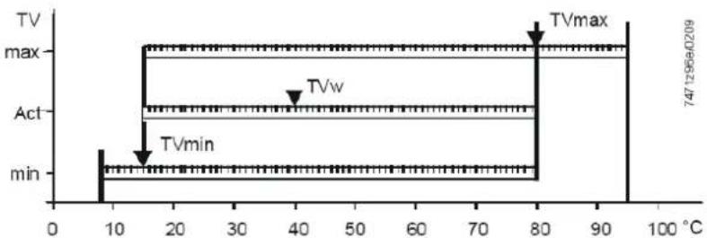
line
| Time (°C) | Value |
|-----------|-----------|
| 0 | 747.7296e-0209 |
| 10 | 747.7296e-0209 |
| 20 | 747.7296e-0209 |
| 30 | 747.7296e-0209 |
| 40 | 747.7296e-0209 |
| 50 | 747.7296e-0209 |
| 60 | 747.7296e-0209 |
| 70 | 747.7296e-0209 |
| 80 | 747.7296e-0209 |
| 90 | 747.7296e-0209 |
| 100 | 747.7296e-0209 |
TVmax Flow temperature setpoint, maximum
TVmin Flow temperature setpoint, minimum
TVw Current flow temperature setpoint
Syst pump on heat gen lock
This parameter can be used to select whether or not the system pump shall be locked when heat generation lock is active.
| Line no. | Operating line | Factory setting |
| 2121 Syst pump on heat gen lockOffOn | See manual boiler |
Off
System pump not locked.
On
System pump locked when heat generation lock is active.
Primary controller / system pump
Mixing valve control
Mixing valve boost
To ensure accurate control, the flow temperature delivered by the boiler must be higher than the demanded flow temperature setpoint after the mixing valve. The controller therefore generates the boiler temperature setpoint based on the mixing valve boost set here and the current flow temperature setpoint.
Actuator type
The selection of the type of actuator determines the control behavior for the type of mixing valve actuator used.
2-position
The controller drives the actuator via one relay output only. When a control signal is delivered, the valve opens. When no control signal is present, the valve closes automatically (thermal action or mechanically).
The control employs a 2-position controller with an adjustable switching differential. If the flow temperature lies more than half the switching differential below the setpoint, relay Mixing valve OPEN is energized to remain energized until the flow temperature reaches a level half the switching differential above the setpoint.
3-position
The controller drives the actuator via 2 relay outputs. One of the outputs is used for opening the valve, one for closing the valve. If none of the relays is energized, the actuator maintains its present position.
| Line no. | Operating line | Factory setting |
| 2130 Mixing valve boost | See manual boiler |
| 2132 Actuator type2-position3-position |
| 2133 Switching differential 2-pos |
| 2134 Actuator running time |
| 2135 Mixing valve Xp |
| 2136 Mixing valve Tn |
The control employs a PID controller whose proportional band (Xp) and integral action time (Tn) can be parameterized. The actuator running time can also be adjusted. The controller's neutral zone is +/- 1 K. The control parameters can be matched to the requirements of difficult controlled systems.
Switching differential 2-pos
For a 2-position actuator, the 2-position switching differential must also be dapted. This is not required when using a 3-position actuator.
Actuator running time
Setting the running time of the actuator used with the mixing valve.
Mixing valve Xp
By setting the right proportional band, the control action of the mixing valve's actuator is matched to the behavior of the plant (controlled system). Xp influences the controller's P-control action.
Mixing valve Tn
By setting the right integral action time, the control action of the mixing valve's actuator is matched to the behavior of the plant (controlled system). Tn influences the controller's I-control action.
Primary contr/system pump
If the plant is equipped with a buffer storage tan, it must be stated here whether – hydraulically speaking – the primary controller or the system pump is located before or after the buffer storage tank.
| Line no. | Operating line Factory setting | |
| 2150 | Primary contr/system pumpBefore the bufferAfter the buffer | See manual boiler |
Setpoints
The controlled boiler temperature set-point can be limited with Setpoint min und -max. These limitations can be considered to be a protective function for the boiler. In normal operation, minimum limitation of the boiler temperature is the lower limit value for the controlled boiler temperature setpoint, depending on the boiler's operating mode. In normal operation, maximum limitation of the boiler temperature is the upper limit value for the controlled boiler temperature setpoint and setpoint for the electronic limit thermostat (TR).
Line no. Operating line
2210 Setpoint min
2212 Setpoint max
2214 Setpoint manual control
Setpoint manual control
In manual control, the common flow temperature setpoint can be set to a fixed value.
Factory setting
See manual boiler
PID boiler management unit
P-band Xp defines the controller's gain. A small Xp leads to higher control of the burner fan without changing the control difference T = (Tsoll minus Tist) .
The integral action time Tn determines the controller's rate of response when correcting proportional offsets. A shorter Tn leads to faster correcting actions.
Line no. Operating line
2233 P-band Xp HCs
2234 Int action time Tn HCs
2235 Der action time Tv HCs
2236 P-band Xp DHW
The derivative action time Tv determines the extent of after-effect of a spontaneous change of control difference. A short Tv only has a short-time impact on the manipulated variable.
Factory setting
See manual boiler
Boiler / burner control
Burner running time min
Here, a period of time after burner startup is defined during which the off time differential is increased by 50%. This means that with similar heating up processes, the 2-position controller switches off later. But this parameter setting does not guarantee that the burner remains in operation for the parameterized period of time.
Line no. Operating line
2241 Burner running time min
2243 Burner off time min
2245 SD burner off time
SD burner off time
If SD burner off time is exceeded, the minimum off time will be aborted.
Factory setting
See manual boiler
Burner off time min
The minimum boiler off time takes effect exclusively between successive heat requests. It locks the boiler for an adjustable period of time and is started after regular shutdown or if the temperature limiter cuts out in response to heat requests. New startups initiated by the 2-position controller due to heat requests are made only when this period of time has elapsed.
Overtemperature protection
Pump overrun time
Pump overrun time after heating mode and external requests.
| Line no. Operating line | Factory setting |
| 2250 Pump overrun time | See manual boiler |
| 2253 Pump overr time after DHW |
Pump overr time after DHW
Pump overrun time after DHW heating.
Return setpoint min
The required minimum return temperature setpoint can be parameterized. If the boiler return temperature falls below the return temperature setpoint, maintained boiler return temperature becomes active.
In connection with the return temperature, the following functions can be provided:
- Locking signal acting on the consumers
| Line no. Operating line | Factory setting |
| 2270 Return setpoint min | See manual boiler |
- Control of the bypass pump
- Control of a modulating valve
Boiler pump
Boiler pump on heat gen lock
This parameter is used to determine whether heat generation lock shall also act on the boiler pump.
| Line no. | Operating line | Factory setting |
| 2301 | Boiler pump on heat gen lock | See manual boiler |
| 2305 | Impact heat generation lockHeating mode onlyHeating and DHW mode |
Off
Boiler pump locked when heat generation lock is active.
All space heating and DHW heating requests are locked.
On
Boiler pump not locked when heat generation lock is active.
Impact heat generation lock
This parameter is used to select whether heat generation lock shall only be active in the case of heat requests from the heating circuit, or in the case of DHW heating requests also.
Heating mode only
Only space heating requests are locked. DHW heating requests continue to be met.
Temp differential nominal
Temp differential max
The "Maximum boiler differential" function is used to monitor the speed control of the boiler pump. When the boiler flow/return differential reaches the preset value, the boiler pump speed is not increased further. If the actual differential exceeds the preset value, the speed is reduced.
The function can be deactivated with setting ---.
| Line no. | Operating line | Factory setting |
| 2316 | Temp differential max | See manual boiler |
| 2317 | Temp differential nominal |
Temp differential nominal
In connection with a modulating heating circuit pump, the boiler maintains a nominal temperature differential as long as the pump is not operated at the maximum permissible speed.
Speed control
Pump modulation
A number of functions are available for the modulating boiler pump.
None
Function is switched-off.
Demand
Do not use this function.
Boiler setpoint
Do not use this function.
Temp differential nominal
The LMS... continues to control the boiler's output such that the boiler temperature setpoint is maintained. Pump speed control controls the boiler pump's speed in a way that the parameterized nominal temperature differential of boiler return and boiler flow is maintained. If the effective differential is greater than the nominal differential, the pump's speed is increased, otherwise it is decreased.
The pump's speed is limited by the parameterized minimum and maximum speed.
Burner output
This function can be used with both single-boiler plants and cascades, with or without pressureless header.
If the burner operates at low output, the boiler pump shall also be operated at low speed. In the case of high outputs, the boiler pump shall run at high speed.
| Line no. | Operating line | Factory setting |
| 2320 | Pump modulationNoneDemandBoiler setpointTemp differential nominalBurner output | See manual boiler |
| 2321 | Starting speed |
| 2322 | Pump speed min |
| 2323 | Pump speed max |
| 2324 | Speed Xp |
| 2325 | Speed Tn |
| 2326 | Speed Tv |
| 2329 | Pump setpoint reduction |
| 2334 | Output at pump speed min |
| 2335 | Output at pump speed max |
The speed of the boiler pump is calculated based on the current boiler output. Up to a selectable boiler output (operating line 2334) the boiler pump operates at minimum speed. And above a selectable boiler output (operating line 2335), the boiler pump operates at maximum speed. Between minimum output (Ynmin) and maximum output (Ynmax), the pump speed is continuously increased.
Starting speed
At start up the pump will start with the programmed starting speed. After modulation release the pump will be controlled according to the chosen function.
Pump speed min
Minimum speed for the pump.
Pump speed max
Maximum speed for the pump.
Speed Xp
Speed Tn
Speed Tv
PID settings for function Boiler setpoint at parameter 2320.
Pump setpoint reduction
This parameter is used to set the setpoint reduction for the boiler pump's speed control. This setpoint reduction is only active in connection with Pump modulation and Boiler setpoint (operating line 2320).
Output at pump speed min Output at pump speed max
If option Burner output is selected on operating line number 2320, the boiler pump is operated at minimum speed until the burner output set on operating line number 2334 is reached, and at maximum speed from the burner output set on operating line number 2335. If the burner's output lies between these 2 values, the boiler pump's speed is calculated through linear conversion.
Output data
Output nominal
Output basic stage
These setting are required when several boilers with different outputs are operated in a cascade.
| Line no. Operating line | Factory setting |
| 2330 Output nominal | See manual boiler |
| 2331 Output basic stage |
Fan
Fan speed heating max
This parameter can be used to limit the maximum output in heating mode.
Fan speed full charging max
This parameter can be used to limit the maximum output during full charging.
Fan speed DHW max
This parameter is used to limit the maximum fan speed for DHW heating. The parameter is OSV-compatible. With OSV, the maximum fan speed applies to DHW heating.
Fan shutdown heating mode
This function is used to switch off the fan's power supply. Power supply to the fan is released as soon as the fan's PWM control is active or whenever there is a request for DHW. Fan shutdown is delayed and takes place after PWM control is switched off, or after there is no more demand for DHW. The delay time can be set via parameter Fan shutdown delay. During the period of time a request for DHW is active, the fan's power supply remains released also when PWM control is inactive. Parameter Fan shutdown with heat request (fan release configuration) can be used to select whether the fan's power supply shall be released also when there is a request for DHW, independent of PWM control.
Off
Function is deactivated.
On
Function is activated.
| Line no. | Operating line | Factory setting |
| 2441 | Fan speed heating max | See manual boiler |
| 2442 | Fan speed full charging max |
| 2444 | Fan speed DHW max |
| 2445 | Fan shutdown heating modeOffOn |
| 2446 | Fan shutdown delay |
| 2450 | Controller delayOffHeating mode onlyDHW mode onlyHeating and DHW mode |
| 2452 | Controller delay speed |
| 2453 | Controller delay duration |
| 2470 | Delay heat req special op |
Fan shutdown delay
Setting of the delay time for the fan shutdown function.
Controller delay
Here, it can be selected in which operating mode the controller delay shall become active.
Controller delay speed
Speed delivered during the controller delay time.
Controller delay duration
Duration of controller delay. This delay time is started the moment a flame is definitively detected after ignition.
Delay heat req special op
Parameter Delay heat req special op (2470) can be used to delay burner startup, thus allowing the actuating element to release the heating circuit before the heat source reaches its operating position.
Deaeration function
Using the automatic deaerator installed in the boiler, the function is intended to remove any air from the space heating / DHW system. For that purpose, the pumps in the system are activated and deactivated according to a certain sequence. The Deaeration function is performed in up to 4 preselectable phases. The phases are distinguished in terms of heating circuit deaeration, DHW circuit deaeration, cycled pump control, and static pump control for the entire phase. During these phases, a 3-port valve is driven to a certain position. When the preselected phases of the Deaeration function have elapsed, the function is automatically ended.
When this function is started, the burner control changes to standby, which means that it is off during the whole time the Deaeration function is performed.
Auto deaeration procedure
The deaeration ends automatically.
Off
Function deactivated.
On
Function activated.
| Line no. Operating line | Factory setting |
| 2630 Auto deaeration procedureOffOn | See manual boiler |
| 2655 ON time deaeration |
| 2656 OFF time deaeration |
| 2657 Number of repetitions |
| 2662 Venting time heating circuit |
| 2663 Venting time DHW |
ON time deaeration
On time of the boiler / heating circuit pumps in phases 2 and 4 of the deaeration procedure.
OFF time deaeration
Off time of the boiler / heating circuit pumps in phases 2 and 4 of the deaeration procedure.
Number of repetitions
Number of repetitions of pump switching cycles in phases 2 and 4 of the deaeration procedure.
Venting time heating circuit
Duration of deaeration with continuous control of the boiler / heating circuit pumps in phase 1 of the deaeration procedure.
Venting time DHW
Duration of deaeration with continuous control of the boiler / DHW pumps in phase 3 of the deaeration procedure.
General:
The cascade function and menu are only active when: the LBS Device address (Line no. 6600) is set to 1 and another LMS controller is connected to the LBS bus.
Lead strategy
The sources are switched on and off according to the selected lead strategy while giving consideration to the preset output band. To deactivate the impact of the output band, the limit values must be set to 0% and 100%, and the lead strategy to be selected is Late on, late off.
Late on, early off
Additional boilers are switched on as late as possible (output band max) and switched off again as early as possible (output band max). This means that the smallest possible number of boilers are in operation, or additional boilers operate with short on times.
| Line no. | Operating line | Factory setting |
| 3510 | Lead strategyLate on, early offLate on, late offEarly on, late off | See manual boiler |
| 3511 | Output band min |
| 3512 | Output band max |
Late on, late off
Additional boilers are switched on as late as possible (output band max) and switched off again as late as possible (output band min). This leads to the smallest possible number of switch-on/off actions for the boilers.
Early on, late off
Additional boilers are switched on as early as possible (output band min) and switched off again as late as possible (output band min). This means that the largest possible number of boilers are in operation, or additional boilers operate with the longest possible on times.
Release integral source seq
When, with the heat source currently in operation, the demand for heat cannot be met, the difference being the release integral set here, another boiler is switched on. When the value is increased, additional heat sources are switched on at a slower rate. When the value is decreased, additional heat sources are switched on at a faster rate.
Reset integral source seq
When, with the heat source currently in operation, the demand for heat is exceeded by the reset integral set here, the heat source with the highest priority is shut down. When the value is increased, heat sources operate for longer periods of time (in the case of surplus heat). When the value is decreased, heat sources are switched off at a faster rate.
| Line no. Operating line | Factory setting |
| 3530 Release integral source seq | See manual boiler |
| 3531 Reset integral source seq |
| 3532 Restart lock |
| 3533 Switch on delay |
| 3534 Forced time basic stage |
Restart lock
The restart lock prevents a deactivated heat source from being switched on again. It is released again only after the set time has elapsed. This prevents too frequent switching actions of the heat sources and ensures stable plant operating states.
Switch on delay
Correct adjustment of the switch-on delay ensures that plant operating conditions will be stable. This prevents too frequent switching actions of the boilers (cycling).
In the case of a DHW request, the delay time is fixed at 1 minute.
Forced time basic stage
When switched on, every boiler operates with its basic stage for the period of time set here. The next stage is released only when this period of time has elapsed.
Boiler sequence
Auto source seq ch'over
With automatic source sequence changeover, the boiler loads in a cascade can be influenced by defining the order of lead and lag boiler.
Fixed order
Setting - - - defines a fixed order. In that case, the lead boiler can be selected on operating line 3544; the other boilers are then switched on and off in the same order as the LPB device addresses.
Order according to the number of operating hours
On completion of the number of hours set, the boiler sequence in the cascade changes. It is always the boiler with the next higher device address which assumes the role of the lead boiler.
Auto source seq excluding
Setting automatic source sequence exclusion is only used in connection with the activated heat source sequence (operating line 3540). Using automatic source sequence exclusion, the first and / or the last boiler can be exempted from automatic changeover.
None.
The order of switching on the boilers changes when the number of hours set is reached (operating line 3540).
First
The first boiler in terms of addressing will always be the lead boiler. With the other boilers, the order of switching on changes when the set number of hours is reached (operating line 3540).
Last
The last boiler in terms of addressing will always be the last. The other boilers change when the set number of hours is reached (operating line 3540).
First and last
The first boiler in terms of addressing will always be the lead boiler. The last boiler in terms of addressing will always be the last. The boilers in between change when the set number of hours is reached (operating line 3540).
| Line no. | Operating line | Factory setting |
| 3540 | Auto source seq ch'over | See manual boiler |
| 3541 | Auto source sez excluding NoneFirstLastFirst and last |
| 3544 | Leading sourceSource 1... source 16 |
| 3560 | Return setpoint min |
Leading source
The leading source is only selected in connection with the fixed order of the heat source sequence (operating line 3540).
The boiler selected as the lead boiler is always the first to be switched on, or the last to be switched off. The other boilers are switched on and off in the order of their device addresses.
Return setpoint min
If the return temperature drops below the adjusted return setpoint, maintained boiler return temperature becomes active. Maintained boiler return temperature allows consumers to be influenced or a return temperature controller to be used.
General:
The solar function and menu are only active when in the Configuration menu a multifunctional output 5891, 6030-6038 is programmed as solar function and the dedicated multifunctional sensor inputs 5930, 5931, 6040-6045 are activated.
Solar
Charging controller (dT)
For charging the storage tank via the heat exchanger, the temperature differential between collector and storage tank/swimming pool must be sufficient, and the collector must have reached the minimum charging temperature for the storage tank/swimming pool.
| Line no. | Operating line | Factory setting |
| 3810 | Temp diff on | See manual boiler |
| 3811 | Temp diff off |
| 3812 | Charg temp min DHW |
| 3813 | Temp diff on buffer |
| 3814 | Temp diff off buffer |
| 3815 | Charging temp min buffer |
| 3816 | Temp diff on swi pool |
| 3817 | Temp diff off swi pool |
| 3818 | Charging temp min swi pool |
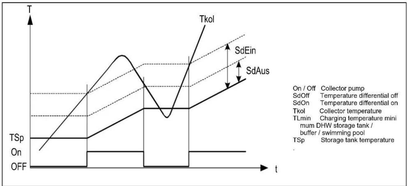
line
| Parameter | Value |
| --------- | ----- |
| On / Off | Collector pump |
| SdOff | Temperature differential off |
| SdOn | Temperature differential on |
| Tkol | Collector temperature |
| TLmin | Charging temperature mini mum DHW storage tank / buffer / swimming pool |
| TSp | Storage tank temperature |
Priority
The priority circuit for the swimming pool (operating line 2065) can impact storage tank priority of solar charging and possibly charge the swimming pool before the storage tanks.
Charging prio storage tank
If a plant uses several heat exchangers, it is possible to set a priority for the integrated storage tanks, which defines the charging sequence.
None
Every storage tank is charged alternately by 5 °C at a time, until every setpoint of level A, B or C (see below) is reached. The setpoints of the next higher level are approached only when all setpoints of the previous level have been reached.
DHW storage tank
During solar charging, preference is given to the DHW storage tank. At every level A, B or C (see below), it is charged with priority. Only then will the other consumers of the same level be charged. As soon as all setpoints of a level are attained, those of the next level are approached, whereby priority is again given to the DHW storage tank.
Charging time relative prio
If the preferred storage tank cannot be charged in accordance with charging control, priority is transferred to the next storage tank or the swimming pool for the period of time set (e.g. too great temperature differential between collector and storage tank). As soon as the preferred storage tank (according to setting Charging priority storage tank) is again ready to be charged, the transfer of priority will immediately be stopped.
If this parameter is disabled (---) charging proceeds in accordance with the Charging prio storage tank setting.
Waiting time relative prio
During the period of time set, the transfer of priority will be delayed. This prevents relative priority from intervening too frequently.
| Line no. | Operating line | Factory setting |
| 3822 | Charging prio storage tankNoneDHW storage tankBuffer storage tank | See manual boiler |
| Level DHW storage tank Buffer storage tank |
| A 1610 Nominal setpoint | Buffer setpoint (slave pointer) |
| B 5050 Charging Temperature Maximum | 4750 Charging Temperature Maximum |
| C 5051 Storage tank Temperature Maximum | 4751 Storage tank Temperature Maximum |
| Swimming pool (1) |
| 2055 | SetpointSolar heating |
| 2055 | SetpointSolar heating |
| 2070 | Swimming poolTemperatureMaximum |
Buffer storage tank
During solar charging, preference is given to the buffer storage tank. At every level A, B or C (see below), it is charged with priority. Only then will the other consumers of the same level be charged. As soon as all setpoints of a level are attained, those of the next level are approached, whereby priority is again given to the buffer storage tank.
(1) When priority for the swimming pool is activated (operating line 2065), the swimming pool is charged before the storage tanks.
| Line no. | Operating line | Factory setting |
| 3825 | Charging time relative prio | See manual boiler |
| 3826 | Waiting time relative prio |
| 3827 | Waiting time parallel op |
| 3828 | Delay secondary pump |
Waiting time parallel op
If solar output is sufficient and solar charging pumps are used, parallel operation is possible. In that case, the storage tank of the priority model can be the next to be simultaneously charged, in addition to the storage tank to be charged next. Parallel operation can be delayed by introducing a waiting time. This way, in the case of parallel operation, switching on of the storage tanks can be effected in steps. The setting (---) disables parallel operation.
Delay secondary pump
To carry away any cold water resting in the primary circuit, the secondary pump of the external heat exchanger can be delayed.
Start function
Collector start function
If the collector temperature cannot be correctly acquired because the pump is not running (especially in the case of vacuum tubes), the pump can be activated from time to time.
Min run time collector pump
When the collector pump is activated, it remains on for the minimum running time, independent of temperature differentials The minimum running time of the pump can be parameterized and is active with all functions that activate the collector pump.
Collector frost protection
When there is risk of frost at the collector, the collector pump will be activated to prevent the heat-carrying medium from freezing.
- If the collector temperature falls below the frost protection temperature, the collector pump will be activated: TKol < TKolFrost
| Line no. | Operating line | Factory setting |
| 3830 | Collector start function | See manual boiler |
| 3831 | Min run time collector pump |
| 3834 | Collector start funct grad |
Collector start funct grad
The collector pump is activated as soon as the temperature acquired by the collector sensor rises.
| Line no. | Operating line | Factory setting |
| 3840 | Collector frost protection | See manual boiler |
- When the collector temperature returns to a level of 1^ above the frost protection temperature, the collector pump will be deactivated again: TKol > TKolFrost + 1
Collector overtemp prot
If there is a risk of overtemperature at the collector, storage tank charging is continued to reduce the amount of surplus heat. When the storage tank safety temperature is reached, charging will be stopped.
| Line no. | Operating line | Factory setting |
| 3850 | Collector overtemp prot | See manual boiler |
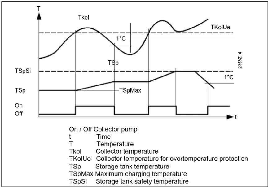
line
| Time | Temperature |
|------|-------------|
| T | 1°C |
| On | Off |
| Off | Off |
Evaporation heat carrier
If there is a risk of the heat carrying medium evaporating due to high collector temperatures, the collector pump will be deactivated to prevent it from reaching excessive temperatures. This is a protective pump function.
| Line no. Operating line | Factory setting |
| 3860 Evaporation heat carrier | See manual boiler |
Speed controlled pump
When the collector pump is connected to multifunctional output QX3. The modulation range of the pump can be limited.
| Line no. | Operating line | Factory setting |
| 3870 | Pump speed min | See manual boiler |
| 3871 | Pump speed max |
Pump speed min / max
The solar pump motor speed is limited by a minimum and maximum permitted speed.
Yield measurement
The 24-hour and total solar energy yield (Line no. 8526, 8527) is calculated, base on these data.
Antifreeze
Since the mixing ratio of the collector medium has an impact on heat transmission, the type of antifreeze used and its concentration must be entered in order to be able to determine the energy yield.
| Line no. | Operating line | Factory setting |
| 3880 | AntifreezeNoneEthylen glycolPrpylene glycolEthyl and propyl glycol | See manual boiler |
| 3881 | Antifreeze concentration |
| 3884 | Pump capacity |
| 3887 | Pulse unit yield |
Pump capacity
The flow rate in l/h of the pump used must be determined and serves for calculating the volume delivered.
Pulse unit yield
Defines the flow per pulse for the chosen Hx-Input. The chosen Hx-Input has to be configured to Pulse measurement accordingly.
General:
The solid fuel boiler function and menu are only active when in the Configuration menu a multifunctional output 5891, 6030-6038 is programmed as solid fuel boiler function and the dedicated multifunctional sensor inputs 5930, 5931, 6040-6045 are activated.
Locks other heat sources
When the solid fuel boiler is put into operation, other heat sources, such as oil/gas boilers, will be locked. Locking takes place as soon as the boiler temperature rises to a degree that crossing of the comparative temperature (Line no. 4133) can be expected.
| Line no. | Operating line | Factory setting |
| 4102 | Locks other heat sources | See manual boiler |
This anticipating function enables the locked heat sources to terminate any overrun of pumps before the solid fuel boiler pump is activated.
Also, in the case of a common stack, it can be made certain that only one boiler is in operation at a time.
Setpoints, Temperature diffs
The boiler pump will be put into operation only when the boiler temperature has reached a minimum temperature level, in addition to the required temperature differential. Above this minimum temperature the boiler should not produce condensate anymore.
Comparative temp
Depending on the hydraulic configuration, the solid fuel boiler temp will be compared to for example the buffer sensor B4.
Delta T-Controller
For the boiler pump to be put into operation, a sufficiently great temperature differential between boiler temperature and comparison temperature is required.
| Line no. | Operating line | Factory setting |
| 4110 | Setpoint min | See manual boiler |
| 4130 | Temp diff on exchanger |
| 4131 | Temp diff off exchanger |
| 4133 | Comparative tempDHW sensor B3DHW sensor B31Buffer sensor B4Buffer sensor B41Flow temp setpointSetpoint min |
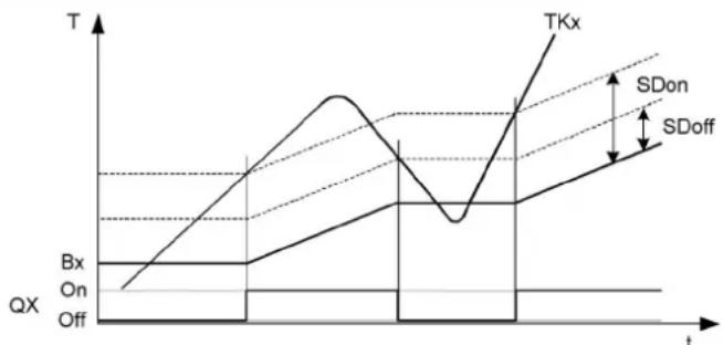
line
| t | Bx | On | Off |
| ---- | ---- | --- | --- |
| Peak | | | |
| Low | | | |
| High | | | |
| Low | | | |
| High | | | |
| High | | | |
| Low | | | |
| High | | | |
| High | | | |
| Low | | | |
| High | | | |
| High | | | |
| Low | | | |
| High | | | |
| High | | | |
| Low | | | |
| High | | | |
| Low | | | |
| High | | | |
| High | | | |
| Low | | | |
| High | | | |
| Low | | | |
| High | | | |
| High | | | |
| Low | | | |
|
| High | | | |
| Low | | | |
| High | | | |
| High | | | |
| Low | | | |
| High | | | |
| Low | | | |
| High | | | |
| High | | | |
| Low | | | |
| High | | Upper Right Y
| | | |
| | | |
| | | |
| | | |
| | | |
| | | |
| | | |
| | | |
| | | |
| | | |
| | | |
| | | |
| | | |
| | | |
| | | |
| | | |
|
| | | |
| | | |
| | | |
| | | |
| | | |
| | | |
| | | |
| | | |
| | | |
| | | |
| | | |
| | | |
| | | |
| | | |
| Lower Left Y: Bx
Lower Right Y: On
Lower Left Y: Off
Upper Left Y: TXx
Lower Right Y: SDon
Lower Left Y: SDoff
Lower Right Y: SDoff
TKx Boiler temp
Bx Comparative temp
On/Off Boiler pump
SDon Temp diff ON
SDoff Temp diff OFF
Excess heat discharge
If the boiler temperature reaches the set maximum value, the solid fuel boiler pump is activated until the boiler temp sinks 5K below the set value. The excess heat is discharged into the Buffer or HCs for which Excess heat draw Line no. 861, 1161, 5085 are activated.
| Line no. Operating line | Factory setting |
| 4141 Excess heat discharge | See manual boiler |
| 4170 Frost prot plant boiler pumpOnOff |
Frost prot plant boiler pump
The boiler pump is activated, depending on the current outside temperature, although there is no heat request.
Frost protection for the solid fuel boiler works only if frost protection for the plant is activated (operating line 6120).
General:
The Buffer function and menu are only active when in the Configuration menu the multifunctional sensor inputs 5930, 5931, 6040-6045 are programmed as B4 and B41. Additionally in the LPB menu the device address has to be set to 1.
Auto generation lock
The automatic heat generation lock brings about a temporary hydraulic separation between heat source and buffer storage tank. The heat source is put into operation only when the buffer storage tank is no longer able to cover the current demand for heat.
| Line no. Operating line | Factory setting |
| 4720 Auto generation lockNoneWith B4 | See manual boiler |
| 4721 Auto heat gen lock SD |
| 4722 Temp diff buffer/HC |
Min st tank temp heat mode
If the tank temperature B4 drops below the set min. tank temp, the HCs are switched off.
| Line no. | Operating line | Factory setting |
| 4724 | Min st tank temp heat mode | See manual boiler |
Overtemperature protection
The buffer will be charged by the solar energy to the set max charging temp.
| Line no. | Operating line | Factory setting |
| 4750 | Charging temp max | See manual boiler |
The overtemperature protection cn reactivate the collector pump until the maximum buffer temperature (fix 90°C) has been reached.
Recooling DHW/HCs
2 functions are available for recooling the buffer storage tank down to the recooling temperature.
- The recooling takes place from the max buffer temperature down to the return temperature.
| Line no. | Operating line | Factory setting |
| 4755 | Recooling temp | See manual boiler |
| 4756 | Recooling DHW/HCs |
| 4757 | Recooling collectorOffSummerAlways |
- The excess heat of the buffer can be drawn by a heat demand of heating or DHW tank. This can be selected for the individual HCs (Line no's 861, 1161, 5085).
- Recooling Collector. In case of a cold collector, the excess heat can be dispersed to the surroundings via the collector field.
Plant hydraulics
Select whether the buffer should be charged by the solar energy. Only the DHW tank or the buffer can be charged by the solar energy.
| Line no. Operating line | Factory setting |
| 4783 With solar integration | See manual boiler |
If there is a certain temperature differential between the common return sensor (B73) and the selectable comparative temperature, the return is diverted through the lower section of the buffer storage tank. The function can be used for a return temperature increase or return temperature decrease (to be selected on operating line 4796).
This is defined on operating line 4796. In addition, the setting of the respective relay output is to be made as Buffer return valve Y15 in configuration Relay output QX1, 2, 3, 4 (operating lines 5890, 5891, 5892 and 5894) and the common return sensor (B73) at BX.
Temp diff on/off return div
The selected temperature differential defines the switch on / off point of return diversion.
Compar temp return div
Selection of the buffer storage tank temperature sensor with which the return temperature is compared in order to switch the return diversion based on the selected temperature differentials.
| Line no. Operating line | Factory setting |
| 4790 Temp diff on return div | See manual boiler |
| 4791 Temp diff off return div |
| Line no. | Operating line | Factory setting |
| 4795 | Compar temp return divWith B4With B41With B42 | See manual boiler |
Optg action return diversion
Selection of the buffer storage tank temperature sensor with which the return temperature is compared in order to switch the return diversion based on the selected temperature differentials.
| Line no. | Operating line | Factory setting |
| 4796 | Optg action return diversionTemp decreaseTemp increase | See manual boiler |
Temp decrease
If the consumers' return temperature is higher than the temperature at the selected sensor (operating line 4795), the return can be used to preheat the lower storage tank section. As a result, the return temperature drops further which, in the case of a condensing boiler, leads to higher efficiency.
Temp increase
If the consumers' return temperature is lower than the temperature at the selected sensor (operating line 4795), the return temperature can be raised by diverting the return through the lower storage tank section. As a result, the return temperature increases.
Partial charging setpoint
By hydraulically decoupling the lower buffer storage tank section, the chargeable storage volume is reduced. As a result, the upper storage tank section is charged in a shorter period of time. The lower storage tank section is only charged when charging of the upper section is completed.
| Line no. | Operating line | Factory setting |
| 4800 | Partial charging setpoint | See manual boiler |
Full charging
Function full buffer storage tank charging enables released heat sources to switch off only when the buffer storage tank is fully charged, in spite of automatic heat generation lock.
| Line no. | Operating line | Factory setting |
| 4810 Full charging | See manual boiler |
| Off |
| Heating mode |
| Always |
Off
The full charging function is deactivated.
Heating mode
Full charging becomes active when due to the buffer storage tank temperature automatic heat generation locks the heat sources while the heat request is valid. When the buffer storage tank's sensor parameterized for the function reaches the required temperature, the function is ended.
Always
Full charging becomes active when due to the buffer storage tank temperature automatic heat generation locks the heat sources while the heat request is valid, or when the heat request becomes invalid. When the buffer storage tank's sensor parameterized for the function reaches the required temperature, the function is ended.
Full charging temp min
The buffer storage tank is charged to at least the set level.
| Line no. | Operating line | Factory setting |
| 4811 | Full charging temp min | See manual boiler |
Full charging sensor
| Line no. | Operating line | Factory setting |
| 4813 | Full charging sensorWith B4With B42/B41 | See manual boiler |
With B4
The full charging function uses buffer sensor B4.
With B42/B41
The full charging function uses buffer sensor B42 or, if not available, buffer sensor B41.
Setting Once/day or Several times/day is active only when the DHW release is set in accordance with the heating circuits' time programs.
Flow setpoint boost
The DHW request to the boiler is made up of the current DHW setpoint plus the adjustable charging boost.
Transfer boost
Heat transfer makes it possible to transport energy from the buffer storage tank to the DHW storage tank. In that case, the actual buffer storage tank temperature must be higher than the actual temperature of the DHW storage tank. The temperature differential can be set here.
Switching diff
If the DHW temperature is lower than the current setpoint minus the switching differential set here, DHW charging is started. DHW charging is ended when the temperature reaches the current setpoint.
Charging time limitation
During DHW charging, space heating may receive no heat or not enough heat, depending on the selected charging priority (operating line 1630) and the hydraulic circuit. For this reason, it is often practical to have a temporal limitation of DHW charging.
Discharging protection
This function ensures that the DHW charging pump (Q3) is activated only when the heat source temperature is high enough.
Charging temp max
Solar energy charges the DHW storage tank up to the adjusted maximum DHW charging level.
The protective collector
overtemperature function can reactivate the collector pump until the maximum storage tank temperature is reached.
Recooling temp
If activated, the recooling function remains in operation until the adjusted recooling temperature in the DHW storage tank is reached.
| Line no. | Operating line | Factory setting |
| 5010 | ChargingOnce/daySeveral times/day | See manual boiler |
| 5020 | Flow setpoint boost |
| 5021 | Transfer boost |
| 5022 | Type of chargingRechargingFull chargingFull charging legioFull Charg 1st time day |
Type of charging
The storage tank can be charged using up to 2 sensors. It is also possible to combine partial charging with 1 sensor and the Legionella function with 2 sensors (setting 3).
| Line no. | Operating line | Factory setting |
| 5024 | Switching diff | See manual boiler |
| 5030 | Charging time limitation |
| 5040 | Discharging protectionOffAlwaysAutomatic |
Application with sensor
The charging pump is activated only when the heat source temperature lies at a level half the charging boost above the DHW temperature. When, during the charging process, the boiler temperature drops to a level below the DHW temperature plus 1/8 the charging boost, the charging pump is deactivated again. If 2 DHW sensors are parameterized for DHW charging, the lower temperature is considered for the Discharging protection function (usually B31).
Application with thermostat
The charging pump is activated only when the boiler temperature lies above the nominal DHW setpoint. When, during the charging process, the boiler temperature drops to a level below the nominal DHW temperature setpoint minus the DHW switching differential, the charging pump is deactivated again.
| Line no. | Operating line | Factory setting |
| 5050 | Charging temp max | See manual boiler |
| 5055 | Recooling temp |
| 5056 | Recooling heat gen/HCs |
| 5057 | Recooling collectorOffSummerAlways |
Recooling heat gen/HCs
Heating energy can be drawn off either by space heating or the DHW storage tank. This can be selected separately for each heating circuit (operating page heating circuit 1...).
Recooling collector
If the collector is cold, the energy can be emitted to the environment via the collector's surfaces.
In place of the boiler, DHW can also be heated with an electric immersion heater. If DHW heating is provided by an electric immersion heater, no request will be sent to the boiler. The changeover between boiler and electric immersion heater takes place based on the following criteria.
Substitute
The electric immersion heater is only used if the boiler delivers a fault status message or has been shut down via boiler lock. This means that in normal situations the DHW is always heated by the boiler.
| Line no. | Operating line | Factory setting |
| 5060 El | imm heater optg modeSubstituteSummerAlways | See manual boiler |
| 5061 El | immersion heater release24h/dayDHW releaseTime program 4/DHW |
| 5062 El | immersion heater controlExternal thermostatDHW sensor |
Summer
The electric immersion heater is used as soon as all connected heating circuits have switched to summer operation. The DHW is again heated by the boiler as soon as at least 1 of the heating circuits has switched back to heating operation. But the electric immersion heater is also used if the boiler delivers a fault status message or has been shut down via boiler lock.
Always
DHW is heated with the electric immersion heater throughout the year. This means that when using this application, the boiler is never required for DHW heating.
EI immersion heater release
24h/day
The electric immersion heater is continuously released impedently of the time programs.
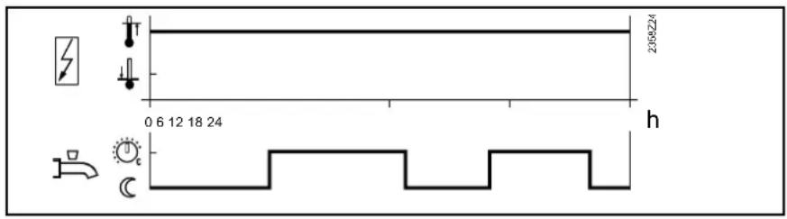
DHW Release
The electric immersion heater is released within the DHW release period.
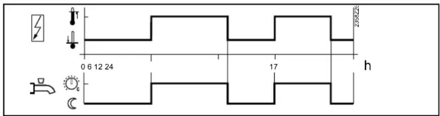
Time program 4/DHW
The electric immersion heater is released within switching program 4.
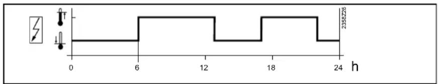
El immersion heater control
External thermostat
The storage tank is charged via an external thermostat without setpoint compensation of the controller.
DHW sensor
The storage tank is charged via an electric immersion heater, with setpoint compensation from the controller.
Important: To ensure that setpoint compensation operates as required, the external control thermostat must be set to the minimum storage temperature.
This function is only active when DHW heating is switched on.
Off
The DHW push can only be triggered manually.
On
If the DHW temperature drops by more than 2 switching differentials (operating line 5024) below the Reduced setpoint (operating line 1612), one-time charging to the nominal DHW setpoint is effected again (operating line 1610).
Legend
SDBW Switching differential DHW
TBWw Nominal DHW temp setpoint
TBWR Reduced DHW temp setpoint
| Line no. | Operating line | Factory setting |
| 5070 | Automatic pushOffOn | See manual boiler |
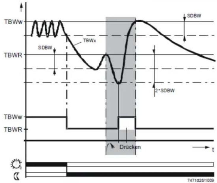
line
| Time Segment | Signal |
| ------------ | ---------- |
| Top Left | TBWw |
| Top Right | SDBW |
| Bottom Left | TBWR |
| Bottom Right| Drücken |
| Bottom Right| SDBW |
Plant hydraulics
Excess heat draw
Excess heat draw can be triggered by one of the following functions:
- Inputs H1, H2, H3 or EX2
- Storage tank recooling
- Solid fuel boiler with excess heat draw
| Line no. Operating line | Factory setting |
| 5085 Excess heat draw | See manual boiler |
When excess heat draw is activated, the surplus energy can be discharged for DHW storage.
With Buffer
If there is a buffer storage tank, specify whether the DHW storage tank can draw heat from it or directly from the boiler.
When using alternative heat sources, the buffer storage tank temperature is used as a control criterion for the release of additional heat sources.
| Line no. Operating line | Factory setting |
| 5090 With Buffer | See manual boiler |
| 5092 With prim contr/system pump |
| 5093 With solar integration |
With prim contr/system pump
It is to be set whether the DHW storage tank receives its heat via the primary controller or with the help of the system pump (depending on the type of plant). The primary controller / system pump will be activated in the LOGON B.
With solar integration
It is to be set whether the DHW storage tank receives its heat from the solar collectors.
Speed control charging pump
The charging pump motor speed is limited by a minimum and maximum permitted speed. On start-up the pump is operated at maximum speed for appr. 10 seconds.
| Line no. Operating line | Factory setting |
| 5101 Pump speed min | See manual boiler |
| 5102 Pump speed max |
Pump speed min
Minimum speed for the pump.
Pump speed max
Maximum speed for the pump.
| Line no. | Operating line | Factory setting |
| 5130 | Transfer strategyOffAlwaysDHW Release | See manual boiler |
Off
There is no heat transfer via charging pump Q3. For the transfer of heat via charging pump Q11, setting DHW release applies in this case.
Always
The transfer can always happen.
DHW Release
The transfer can only happen during DHW release.
Comparison temp transfer
For the transfer the corresponding DHW sensor can be chosen as comparison temperature.
| Line no. | Operating line | Factory setting |
| 5131 | Comparison temp transferDHW sensor B3DHW sensor B31 | See manual boiler |
In the configuration menu general parameters can be programmed.
Presetting
Via presetting one of 30 so called preselect configurations can be chosen. When doing so, the controller will automatically preset various line nr's according to the chosen configuration.
Afterwards individual parameters can be changed to adapt to the demands.
The plant diagram is determined by the preselect and the attached sensors.
| Line no. | Operating line | Factory setting |
| 5700 | Preselect | See manual boiler |
Line no. 5700 Preselct can show the following:
Unchanged:
All parameters that were preset by the Preselect function have the preselect settings.
Changed:
Parameters that were preset by the Preselect function have been adapted manually.
Heating circuit 1, 2
The HCs can be switched on or off.
| Line no. | Operating line | Factory setting |
| 5710 | Heating circuit 1 | See manual boiler |
| 5715 | Heating circuit 2 |
DHW Sensor
DHW sensor B3
The controller calculates the switching points including the switching differential from the DHW setpoint and the acquired DHW storage tank temperature.
Thermostat
The DHW temperature is controlled based on the switching state of a thermostat connected to DHW sensor B3.
| Line no. | Operating line | Factory setting |
| 5730 | DHW SensorDHW sensor B3Thermostat | See manual boiler |
- When using a DHW thermostat, Reduced mode is not possible. This means that
- when Reduced mode is active, DHW heating with the thermostat is locked.
-
The adjustment of the nominal DHW temperature setpoint must be equal to or higher than the setpoint adjustment on the thermostat (thermostat calibrated at switch-off point).
-
The flow temperature setpoint for DHW must be set to a minimum of 10 °C (has an impact on the charging time).
- In that case, the DHW is not protected against frost.
The DHW is charged via a pump connected to Q3/Y3.
| Line no. | Operating line | Factory setting |
| 5731 DHW controlling element Q3No charging elementCharging pumpDiverting valve | See manual boiler |
Diverting valve
The DHW is charged via a diverting valve connected to Q3/Y3. In this setting pump Q2 will be set to boilerpump, if the boiler pump has not already been programmed at a Relay output QX...
The basic position of the diverting valve is the position the valve maintains when there is no heat request.
Last request
On completion of the last heat request, the diverting valve maintains position it held last.
| Line no. | Operating line | Factory setting |
| 5734 | Basic pos DHW div valveLast requestHeating circuitDHW | See manual boiler |
Heating circuit
On completion of the last heat request, the diverting valve is driven to the heating circuit position.
DHW
On completion of the last heat request, the diverting valve is driven to the DHW position.
The separate circuit can only be employed if a boiler cascade is used.
For the separate circuit, DHW controlling element Q3 must be set to Diverting valve.
| Line no. | Operating line | Factory setting |
| 5736 DHW separate circuitOffOn | See manual boiler |
Off
The separate circuit is switched off. Every boiler in use can charge the DHW storage tank.
On
The separate circuit is switched on. DHW charging takes place exclusively via the boiler defined for that purpose.
Here, the diverting valve position is set that applies when the output is active.
| Line no. | Operating line | Factory setting |
| 5737 | Optg action DHW div valvePosition on DHWPosition on heating circuit | See manual boiler |
Position On DHW
When the output is active, the diverting valve is in the DHW position.
Position on heating circuit
When the output is active, the diverting valve is in the heating circuit position.
Here, the DHW diverting valve can be driven to the midposition. This serves for filling or draining both heating circuits. This action must be reset manually.
| Line no. | Operating line | Factory setting |
| 5738 | Midposition DHW div valveOffOn | See manual boiler |
Off
The diverting valve is driven to position currently demanded, independent of heat requests and the basic position.
On
The diverting valve is driven to the mid-position.
Ctrl boiler pump/DHW valve
This parameter is for use with special hydraulic schemes to define that boiler pump Q1 and diverting valve Q3 are only in charge of DHW and heating circuit 1, but not of heating circuit 2 and of external consumer circuits.
| Line no. | Operating line | Factory setting |
| 5774 Steuer' Kesselpump/TWW UVAll requestsRequest HC1/DHW only | See manual boiler |
All requests
Hydraulically speaking, the diverting valve is integrated with all heat requests and changes over between DHW mode and the other heat requests. The boiler pump runs, no matter what the heat request.
Request HC1/DHW only
In place of a collector pump and diverting valves for integrating the storage tanks, the solar plant can also be operated with charging pumps.
| Line no. | Operating line | Factory setting |
| 5840 | Solar controlling elementCharging pumpDiverting valve | See manual boiler |
Charging pump
When using a charging pump, all heat exchangers can be used at the same time. Either parallel or alternative operation is possible.
Diverting valve
When using a diverting valve, it is always only 1 heat exchanger that can be used at a time. Only alternative operation is possible.
External solar exchanger
In the case of solar plants with 2 storage tanks, it must be selected whether there is an external heat exchanger used for both the DHW and the buffer storage tank, or for 1 of them only.
| Line no. | Operating line | Factory setting |
| 5841 | External solar exchangerJointlyDHW storage tankBuffer storage tank | See manual boiler |
Combi storage tank
Functions specific to combi storage tanks are activated with this setting. For example the electric immersion heater in the buffer storage tank can be used for both space heating and DHW heating.
| Line no. | Operating line | Factory setting |
| 5870 | Combi storage tankNoYes | See manual boiler |
No
No combi storage tank present.
Yes
Combi storage tank present.
Relais output QX
The settings of the relay outputs add additional functions to the plant diagram.
QX2 is a relay output of LMS14. QX21, 22, 23 are relay output on AVS75 modules.
Circulating pump Q4
The connected pump serves as a DHW circulating pump. Operation of the pump can be scheduled as required on operating page DHW, operating line Release circulating pump (Line no. 1660).
Using the connected electric immersion heater, the DHW can be heated up according to operating page DHW storage tank, operating line electric immersion heater. Line no. 5060 should be programmed appropriately.
Collector pump Q5
When using a solar collector, a circulating pump for the collector circuit is required.
Cons circuit pump VK1/2/3
External request pump 1 can be used for an additional consumer. Together with an external request for heat at input external request 1, it is possible to operate an air heater or similar.
Boiler pump Q1
The connected pump is used for circulating the boiler water between boiler and low velocity header.
Bypass pump Q12
The connected pump serves as a boiler bypass pump for maintaining the boiler return temperature.
Alarm output K10
The alarm relay signals faults, should they occur. Switching on takes place with a delay of two minutes. When the fault is corrected, that is, when the fault status is no longer present, the relay will be deenergized with no delay. If the fault cannot immediately be corrected, it is still possible to reset the alarm relay. This is made on operating page Faults (Line no. 6710).
| Line no. | Operating line | Factory setting |
| | |
| 5890 | Relais output QX | |
| 5891 | None | |
| 5892 | Circulating pump Q4El imm heater DHW K6Collector pump Q5 | |
| 6030 | Cons circuit pump VK1 Q15 | |
| 6031 | Boiler pump Q1 | |
| 6032 | Bypass pump Q12 | |
| 6033 | Alarm output K10 | |
| 6034 | 2nd pump speed HC1 Q21 | |
| 6035 | 2nd pump speed HC2 Q22 | |
| 6036 | 2nd pump speed HC3 Q23 | |
| 6037 | Heat circuit pump HC3 Q20 | |
| 6038 | Cons circuit pump VK2 Q18System pump Q14Heat gen shutoff valve Y4Solid fuel boiler pump Q10Time program 5 K13Buffer return valve Y15Solar pump ext exch K9Solar ctrl elem buffer K8Solar ctrl elem swi pool K18Cons circuit pump VK3 Q19Cascade pump Q25St tank transfer pump Q11DHW mixing pump Q35DHW interm circ pump Q33Heat request K27Refrigeration request K28Heat circuit pump HC1 Q2Heat circuit pump HC2 Q6DHW ctrl elem Q3Instant heater ctrl elem Q34Water filling K342nd boiler pump speed Q27Status output K35Status information K36Flue gas damper K37Fan shutdown K38 | See manual boiler |
2nd pump speed HC1/2/3
This function allows the control of a 2-stage heating circuit pump, so that when heating load is reduced the pump load can be reduced as well.
The relay output QX is used to switch on the 2nd stage.
| 1st stageOutput Q2/Q6/Q20 | 2nd StageOutput Q21/Q22/Q23 | Pump mode |
| Off Off Off | | |
| On Off Min load | | |
| On On Full load | | |
Heat circuit pump Q20
(for direct circuit)
The direct circuit will be activated.
Time program:
For the direct circuit only Time program 3/HC3 can be used. Also check menu "Time program 3/HC3".
System pump Q14
The connected pump serves as a system pump, which can be used to supply heat to additional consumers. The system pump is put into operation as soon as there is a heat request from one of the consumers. If there is no heat request, the pump is deactivated on completion of the overrun time.
Heat gen shutoff valve Y4
If the buffer storage tank holds a sufficient amount of heat, the consumers can draw their heat from it, and the heat sources need not be put into operation. Automatic heat generation lock locks the heat sources and hydraulically disconnects them from the rest of the plant with the help of heat source shut-off valve Y4. This means that the heat consumers draw their energy from the buffer storage tank and wrong circulation through the heat sources will be eliminated.
Solid fuel boiler pump Q10
For the connection of a solid fuel boiler, a circulating pump for the boiler circuit is required.
Time program 5 K13
The relay is controlled according to the settings made in time program 5.
Buffer return valve Y15
This valve must be configured for return temperature increase / decrease or partial charging of the buffer storage tank.
Solar pump ext. exch K9
For the external heat exchanger, solar pump external exchanger K9 must be set at the multifunctional relay output (QX). If both a DHW and a buffer storage tank are available, operating line 5841 External solar heat exchanger must also be set.
Solar ctrl elem buffer K8
If several heat exchangers are used, the buffer storage tank must be set at the respective relay output and, in addition, the type of solar controlling element must be defined on operating line 5840).
Solar ctrl elem swi pool K18
If several heat exchangers are used, the swimming pool must be set at the respective relay output and, in addition, the type of solar controlling element must be defined on operating line 5840).
Swimming pool pum Q16
External request pump 3 can be used for an additional consumer. Together with an external request for heat at input external request 3, it is possible to operate an air heater or similar.
Cascade pump Q25
Common boiler pump for all boilers in a cascade.
St tank transfer pump Q11
If the temperature level of the buffer storage tank is high enough, the DHW storage tank can be charged by the buffer. This transfer can be made by means of storage tank transfer pump Q11.
DHW mixing pump Q35
Separate pump for storage tank circulation during the time the legionella function is active.
Charging pump with DHW storage tank using an external heat exchanger.
Heat request K27
Contact closes to inform an external heat source that a heat demand is pending.
Refrigeration request K28
Function not yet implemented.
Heat circuit pump HC1 Q2
Pump HC1 will be activated.
Hat circuit pump HC2 Q6
Pump HC2 will be activated.
DHW ctrl elem Q3
Control element for DHW storage tank.
Instant WH ctrl elem Q34
Ctrl element for DHW instantaneous.
2nd boiler pump speed Q27
Speed 2 of the boiler pump will be activated.
Status output K35
Function status output.
Function status information.
Flue gas damper K37
Function flue gas damper.
Fan shutdown K38
Function "Fan shutdown" to turn off power supply when the fan is not needed.
Depending on the selection made, the sensor input settings assign appropriate functions.
BX1 and 2 are sensor inputs of the LMS14. BX21 and 22 are sensor inputs on the AVS75 modules.
None
Sensor input with no function.
DHW sensor B31
DHW storage tank sensor at the bottom.
Return sensor B7
Not a safety-related boiler return temperature sensor.
Buffer storage tank sensor at the top.
Buffer sensor B41
Buffer storage tank sensor at the bottom.
Buffer sensor B42
Third buffer storage tank sensor (in the middle).
Solar flow sensor B63
Solar flow temperature sensor for yield measurement.
Solar return sensor B64
Solar return temperature sensor for yield measurement
| Line no. | Operating line | Factory setting |
| 5930 | Sensor input BX1, BX2 | |
| 5931 | None | |
| 5932 | DHW sensor B31 | |
| Collector sensor B6 | |
| Return sensor B7 | |
| 6040 | DHW circulation sensor B39 | |
| 6041 | Buffer sensor B4 | |
| 6042 | Buffer sensor B41 | |
| 6043 | Flue gas temp sensor B8 | |
| 6044 | Common flow sensor B10 | See manual boiler |
| 6045 | Solid fuel boiler sensor B22 | |
| DHW charging sensor B36 | |
| Buffer sensor B42 | |
| Common return sensor B73 | |
| Cascade return sensor B70 | |
| Swimming pool sensor B13 | |
| Solar flow sensor B63 | |
| Solar return sensor B64 | |
| Primary exch sensor B26 | |
Optg mode changeover
HC
The operating modes of the heating circuits are switched to Protection mode via the Hx input (e.g. using a remote telephone switch).
DHW
DHW heating is locked only when using setting HCs+DHW or DHW.
Heat generation lock
The heat source is be locked via the Hx terminals. All temperature requests made by the heating circuits and by DHW will be ignored. Frost protection for the boiler will be maintained.
Error/Alarm message
Input H1 generates a controller-internal error message. If the "Alarm output" (relay outputs QX1 - 4, operating lines 5891 - 5894) is appropriately configured, the error message will be forwarded or displayed by an additional contact (e.g. an external lamp or horn).
Consumer request VK1/VK2/VK3
The adjusted flow temperature setpoint will be activated via terminal Hx (e.g. an air heater function for a warm air curtain) closes its contact. The setpoint can be programmed on Line no. 1859, 1909 and 1959.
Excess heat discharge
Active dissipation of excess heat enables an external heat source to force consumers (heating circuit, DHW storage tank, Hx pump) to draw excess heat by delivering a forced signal. Parameter Excess heat draw can be used to determine for every consumer whether or not it should take account of the forced signal and, hence, whether or not that consumer should participate in the dissipation of heat.
- Local effect
When using LPB device address 0 or >1, excess heat discharge only acts on the local consumers connected to the controller.
| Line no. | Operating line | Factory setting |
| 5950 | Function Input H1/H2/H4/H5 | |
| 5970 | None | |
| 5977 | Optg mode change HCs+DHW | |
| Optg mode changeover DHW | |
| 6046 | Optg mode changeover HCs | |
| 6054 | Optg mode changeover HC1 | |
| 6062 | Optg mode changeover HC2 | |
| Optg mode changeover HC3 | |
| Heat generation lock | |
| Error/alarm message | |
| Consumer request VK1 | |
| Consumer request VK2 | |
| Consumer request VK3 | |
| Excess heat discharge | |
| Release swi pool solar | |
| Operating level DHW | See manual boiler |
| Operating level HC1 | |
| Operating level HC2 | |
| Operating level HC3 | |
| Room thermostat HC1 | |
| Room thermostat HC2 | |
| Room thermostat HC3 | |
| DHW flow switch | |
| DHW thermostat | |
| Start prevention | |
| Consumer request VK1 10V | |
| Consumer request VK2 10V | |
| Consumer request VK3 10V | |
| Pressure measurement 10V | |
| Preselected output 10V | |
• Central effect (LPB)
When using LPB device address = 1, excess heat discharge also acts on the consumers connected to the other controllers in the same segment.
The distribution of excess heat from segment 0 across other segments of the system is not possible.
Release swi pool solar
The function can be used to enable solar heating of the swimming pool externally (e.g. with a manual switch) or to define solar charging priority over storage.
Configuration:
Set the function of input Hx to Release swimming pool solar. Refer to operating line 2065 "Charging priority solar" for a description of the function.
The operating level can be set via the contact in place of using the internal time program (external time program).
Room thermostat HC1/HC2/HC3
The input can be used to generate a room thermostat request for the selected heating circuit.
DHW flow switch
Input from the flow switch of the instantaneous water heater.
DHW thermostat
Input from the DHW storage tank thermostat.
Start prevention
This input can be used to prevent burner starts.
Consumer request VK1/VK2/VK3 10V
Application node "External load x" receives heat requests in the form of voltage signals (DC 0...10 V). The linear characteristic is defined with the help of 2 fixed points (voltage value 1 / function value 1 and voltage value 2 / function value 2).
Pressure measurement DC 10 V
The voltage signal present at input Hx is converted to a pressure value (linear conversion). The linear characteristic is defined by 2 fixed points (voltage value 1 / function value 1 and voltage value 2 / function value 2).
Preselected output 10V
The heat source receives a voltage signal (DC 0...10V) as an output request. The linear characteristic is defined with the help of 2 fixed points (voltage value 1 / function value 1 and voltage value 2 / function value 2).
NC
The contact is normally closed and must be opened to activate the selected function.
NO
The contact is normally open and must be closed to activate the selected function.
The linear characteristic is defined via 2 fixed points. The setting uses 2 parameter pairs for Function value and Voltage value (F1/U1 and F2/U2). At input H4 (frequency input), a frequency value is assigned to the function value, and not a voltage value.
| Line no. | Operating line | Factory setting |
| 5951604760556063 | Contact type H1/H2NCNO | |
| 5952 Mir. Flow setpoint H1 |
| 5953604960576065 | Voltage value 1 H1/H2 | See manual boiler |
| 5954605060586066 | Function value 1 H1/H2 |
| 5955605160596067 | Voltage value 2 H1/H2 |
| 5956605260606068 | Function value 2 H1/H2 |
| 5971 Contact type H4NCNO |
| 5973 Frequency value 1 H4 |
| 5974 Function value 1 H4 |
| 5975 Frequency value 2 H4 |
| 5976 Function value 2 H4 |
| 5978 Contact type H5NCNO |
Extension module AVS75
Multifunctional
Functions that can be assigned to the multifunctional inputs / outputs appear on operating lines 6030...6038.
Heating circuit 1/2
For this application, the respective settings of operating page Heating circuit 1/2 can be adapted.
Return temp controller
The mixing valve control is part of the return temperature increase function. Settings in menu "Boiler".
None
Input Hx has no function.
Limit thermostat HC
If the extension module for the heating circuit is used, an external limit thermostat (e.g. for underfloor heating) can be connected to input EX21 (AC 230V).
| Line no. | Operating line | Factory setting |
| 6020 | Function Extension module 1/2/3 | |
| 6021 | None | |
| 6022 | Multifunctional HC1 | |
| HC2 | |
| Return temp controller Solar DHW Primary contr/system pump | See manual boiler |
Solar DHW
The relevant settings of operating page "Solar" can be matched to meet the requirements of this application.
Primary contr/system pump
For this application, the respective settings of operating page Primary controller / system pump can be adapted.
| Line no. | Operating line | Factory setting |
| 6024 | Function input EX21 Module 1/2/3 | |
| 6026 | None | See manual boiler |
| 6028 | Limit thermostat HC |
Sensor type collector
Selection of type of sensor used. The controller will use the respective temperature characteristic.
| Line no. | Operating line | Factory setting |
| 6097 | Fühlertyp KollektorNTCPT1000 | See manual boiler |
Readjustm collector sensor
The measured value of the collector sensor can be corrected +/- 20 K.
| Line no. Operating line | Factory setting |
| 6098 Readjustm collector sensor | See manual boiler |
| 6100 Readjustm outside sensor |
The measured value of the outside sensor can be corrected +/- 3 K.
Time constant building
When the outside temperature varies, the room temperature changes at different rates, depending on the building's thermal storage capacity.
| Line no. Operating line | Factory setting |
| 6110 Time constant building | See manual boiler |
The above setting is used to adjust the response of the flow temperature setpoint when the outside temperature varies.
Central setp compensation
Central setpoint compensation matches the setpoint of the heat source to the required central flow temperature. The setting limits the maximum readjustment, even in cases where greater adaptations would be called for.
| Line no. Operating line | Factory setting |
| 6117 Central setp compensation | See manual boiler |
This function can only be implemented when using the common flow sensor (B10).
Setpoint Reduction delay
This function prevents stage boilers or modulating boilers switching off too quickly. This makes the boilers not cool down, to prevent a new heat demand and restart of the boilers.
| Line no. | Operating line Factory setting |
| 6118 Setpoint reduction delay | See manual boiler |
The reduction delay only works when there is a setpoint change, not when the heat demand disappears.
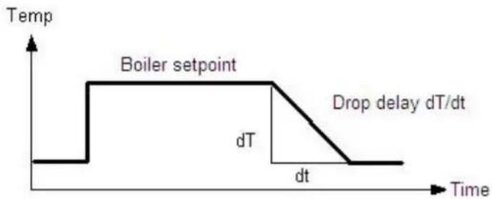
line
| Time | Temperature (°C) |
|------|------------------|
| t1 | 0 |
| t2 | Boiler setpoint |
| dt | dT |
| dt/dT | Drop delay dT/dt |
Frost protection plant
Depending on the actual outside temperature the pumps will be switched on, even if there is no heat demand.
Prerequisite for proper functioning is a fully operational plant. Frost protection for the plant necessitates an outside sensor. If that sensor is missing, the function will nevertheless be ensured by simulating an outside temperature of 0 °C and by delivering an error message.
Off
Function is deactivated.
On
Function is activated.
| Line no. | Operating line Factory setting |
| 6120 Frost protection plantOffOn | See manual boiler |
| Outside temp Pump Diagram | |
| ...-4°C | Continuously ON | ON |
| -5...1.5°C | ON for 10 minutes at 6 hours intervals | Cycle |
| 1.5°C... Continuously OFF OFF | |

bar
| State | Value |
|---|---|
| ON | -5 |
| takt | -4.5 |
| OFF | 1.5 |
Save sensors
At midnight, the basic unit saves the statuses at the sensor terminals, provided the controller has previously been in operation for at least 2 hours.
If, after storage, a sensor fails, the basic unit generates an error message. This setting is used to ensure immediate saving of the sensors. This becomes a requirement when, for instance, a sensor is removed because it is no longer needed.
| Line no. | Operating line Factory setting |
| 6200 Save sensorsNoYes | See manual boiler |
Reset to default parameters
All resettable parameters can be reset to their default values. Exempted from this are the following operating pages: Time of day and date, Operating unit, RF and all time programs, Setpoint "Manual control".
| Line no. | Operating line Factory setting |
| 6205 Reset to default parametersNoYes | See manual boiler |
Plant diagram
To identify the current plant diagram, the basic unit generates a check number. The check no. is made up of the lined up partial diagram numbers.
The meaning of the numbers for the line no.'s can be found in the tables on the next page.
| Line no. | Operating line |
| 6212 Check no. heat source 1 |
| 6213 Check no. heat source 2 |
| 6215 Check no. storage tank |
| 6217 Check no. heating circuits |
Software-Version
The software version indicated here represents the current version of the basic unit.
| Line no. | Operating line |
| 6220 Software version |
Check no. heat source 1 (Line no. 6212)
| Gaskessel modulierend |
| 11 Modulating boiler12 Modulating boiler, boiler pump13 Modulating boiler, bypass pump14 Modulating boiler, boiler pump, bypass pump |
| Solar |
| 0 No Solar1 Solar with collector sensor and - pump |
Check no. heat source 2 (Line no. 6213)
| Solid fuel boiler |
| 0 No solid fuel boiler1 Solid fuel boiler, boiler pump2 Solid fuel boiler, boiler pump, integration DHW storage tank |
Check no. storage tank (Line no. 6215)
| Buffer storage tank | DHW storage tank |
| 0 No storage tank1 Buffer storage tank2 Buffer storage tank, solar connection4 Buffer storage tank, heat source valve5 Buffer storage tank, solar connection, heat source valve | 0 No DHW storage tank1 Electric immersion heater2 Solar connection4 Charging pump5 Charging pump, solar connection13 Diverting valve14 Diverting valve, solar connection16 Primary controller, without heat exchanger17 Primary controller, 1 heat exchanger19 Intermediate circuit, without heat exchanger20 Intermediate circuit, 1 heat exchanger22 Charging pump / intermediate circuit, without heat exchanger23 Charging pump / intermediate circuit, 1 heat exchanger25 Diverting valve / intermediate circuit, without heat exchanger26 Diverting valve / intermediate circuit, 1 heat exchanger |
Check no. heating circuits (Line no. 6217)
| HC 3 | HC 2 | HC 1 |
| 0 No HC1 Circulation via boiler pump2 HC pump3 HC pump, mixing valve | 0 No HC1 Circulation via boiler pump2 HC pump3 HC pump, mixing valve | 0 No HC1 Circulation via boiler pump2 HC pump3 HC pump, mxing valve |
Device address and Segment address
The controller LPB address is divided into 2 parts each consisting of two 2-digit numerals.
Example:
| 14 | . | 16 |
| ↑ | | ↑ |
| Segment address | Device address |
Bus power supply function
The bus power supply enables the bus system to be powered directly by the individual controllers (no central bus power supply). The type of bus power supply can be selected.
Off
No bus power supply via the controller.
Automatically
The bus power supply (LPB) via the controller is automatically switched on and off depending on the requirements of the LPB.
Bus power supply state
The display shows whether the controller currently supplies power to the bus.
Off
The bus power supply via controller is currently inactive.
On
The bus power supply via controller is currently active. At the moment, the controller supplies some of the power required by the bus.
Display system messages
This setting makes it possible to suppress on the connected operating section system messages transmitted via LPB.
No
Error messages are not displayed on the operator unit of the controller.
Yes
Error messages are displayed on the operator unit of the controller.
| Line no. | Operating line Factory setting | |
| 6600 | Device address | See manual boiler |
| 6601 | Segment address |
| 6604 | Bus power supply functionOffAutomatically |
| 6605 | Bus power supply StateOffOn |
| 6610 | Display system messagesNoYes |
| 6620 | Action changeover functionsSegmentSystem |
| 6621 | Summer changeoverLocallyCentrally |
| 6623 | Optg mode changeoverLocallyCentrally |
| 6624 | Manual source lockLocallySegment |
Action changeover functions
The range of action of central changeover can be defined. This applies to the following types of limitation:
- Summer changeover (when selecting Centrally on line 6623)
- Summer changeover (with Centrally setting on operating line 6621)
Segment
Changeover takes place with all controllers in the same segment.
System
Changeover takes place with all controllers in the entire system (in all segments). The controller must be located in segment 0!
Summer changeover
The scope of summer changeover is as follows:
Locally
Local action; the local heating circuit is switched based on operating lines 730, 1030 and 1330.
Centrally
Central action; depending on the setting made on operating line Action changeover functions, either the heating circuits in the segment or those of the entire system are switched based on operating line 730.
Optg mode changeover
In LPB-capable devices, the basic unit with the LPB device address = 1 can adopt the function of a central operating mode changeover. The changeovers on the central basic unit (via H1 / H3) or the "HC operating mode changeover" parameter) then also take effect on the heating circuits and the DHW of the other basic units on the LPB.
The scope of the operating mode changeover via input H is as follows:
Locally
Local action; the local heating circuit is switched on and off.
Centrally
Central action; depending on the setting made on operating line Action changeover functions, either the heating circuits in the segment or those of the entire system are switched based on operating line 730.
Manual source lock
The range of action of source lock is as follows:
Locally
Local action; the local source is locked.
Segment
Central action; all sources of the cascade are locked.
DHW Assignment
Assignment of DHW heating is required only if it is controlled by a heating circuit program (operating lines 1620 and 5061).
Local HCs
DHW is only heated for the local heating circuit.
All HCs in segment
DHW is heated for all heating circuits in the segment.
All HCs in system
DHW is heated for all heating circuits in the system.
With all settings, controllers in holiday mode are also considered for DHW heating.
Note OT limit ext source
Additional generators connected via the LPB bus can be locked or released per its own parameter based on the outside air temperature (e.g. air/water heat pump). This status is distributed via LPB. The master therefore knows in a cascade whether an additional generator (slave) is available per its own employment limits (outside air temperature or not and can switch another generator accordingly.
No
The Ecobit from the external generator is not observed.
Yes
The Ecobit from the external generator is observed and the cascade is controlled per the provided generators.
Caution!
If an LMU control (slave) is connected as an additional generator, the parameter must be set to "No"!
| Line no. | Operating line Factory settings | |
| 6625 | DHW AssignmentLocal HCsAll HCs i segmentAll HCs in system | See manual boiler |
| 6632 | Note OT limit ext sourceNoYes |
| 6640 | Clock modeAutonomouslySlave without remote settingSlave with remote settingMaster |
| 6650 | Outside temp source |
Clock mode
This setting defines the impact of the system time on the controller's time setting.
Autonomously
The time of day on the controller can be readjusted. The controller's time of day is not matched to the system time.
Slave without remote setting
The time of day on the controller cannot be readjusted. The controller's time of day is constantly and automatically matched to the system time.
Slave with remote setting
The time of day on the controller can be readjusted; at the same time, the system time is readjusted since the change is adopted from the master. The controller's time of day is still automatically and constantly matched to the system time.
Master
The time of day on the controller can be readjusted. The time of day on the controller is used for the system. The system time will be readjusted.
Outside temp source
Only 1 outside temperature sensor is required in the LPB plant. This sensor is connected to a freely selectable controller and delivers via LPB the signal to the controllers without sensor. The first numeral to appear on the display is the segment no. followed by the device no.
When a fault is pending, an error message can be displayed on the info level by pressing the Info button. The display describes the cause of the fault.
Message
A fault currently pending in the system is displayed here with the Albatros code indicating where the fault occurred.
SW Diagnostic code
An internal software error currently pending in the system is displayed here with diagnostic code indicating where the error occurred.
| Line no. Operating line Factory setting | |
| 6700 Message | See manual boiler |
| 6705 SW Diagnostic code |
| 6706 Burner ctrl phase lockout pos |
| 6710 Reset Alarm relay |
Burner ctrl phase lockout pos
A fault currently pending in the system is displayed here with the lockout phase indicating where the fault occurred.
Reset alarm relay
When a fault is pending, an alarm can be triggered via relay QX... The QX... relay must be appropriately configured. This setting can be used to reset the alarm relay.
Temperature alarms
This function can be used for maintaining the required flow temperature. If the flow temperature deviates constantly from the required level for more than the period of time set, an error message will be delivered.
| Line no. Operating line Factory setting | |
| 6740 Flow temp 1 Alarm | See manual boiler |
| 6741 Flow temp 2 Alarm |
| 6742 Flow temp 3 Alarm |
| 6743 Boiler temp Alarm |
| 6745 DHW charging Alarm |
History
The basic unit stores the last 20 errors in nonvolatile memory. Every new entry cancels the entry made last. For every error entry, error code, time, internal SW diagnostic code and fault phase of the burner control are stored.
| Line no. Operating line Factory setting | |
| 6800...6996 History ... Indication only | |
Maintenance functions
Burner hours interval / Burner start interval/ Maintenance interval
As soon as the set number of burner hours or burner starts or maintenance interval has elapsed, a maintenance message is displayed. For this message, the number of operating hours and starts of the first burner stage (input E1) are counted.
| Line no. Operating line Factory setting | |
| 7040 | Burner hours interval | See manual boiler |
| 7041 | Burn hrs since maintenance | Indication only |
| 7042 | Burner start interval | See manual boiler |
| 7043 | Burn starts since maint | Indication only |
| 7044 | Maintenance interval | See manual boiler |
| 7045 | Time since maintenance | Indication only |
| 7050 | Fan speed ionization current | See manual boiler |
| 7051 | Message ionization currentNoYes |
Burn hrs since maintenance Burn starts since maint
Time since maintenance
The current value is added up and displayed. On this operating line, the value can be reset to 0.
Fan speed ionization current
This is the fan speed limit from which the burner ionization current maintenance message should be set if – due to too low ionization current – ionization current supervision and thus increased speed are activated.
Message ionization current
Flag to indicate and to reset the burner ionization current maintenance message.
The maintenance message can be reset only if the cause of the message has been rectified.
Chimney sweep function
The burner is started up. To ensure that burner operation will be as continuous as possible, only maximum limitation of the boiler temperature is active to be used as the switch off point.
To reach the minimum boiler temperature of 64 °C as quickly as possible, all consumers are locked for that period of time by an absolute locking signal.
When the boiler temperature exceeds 64 °C, a forced signal forces all consumers to draw heat so ensure that the boiler keeps running.
The boiler temperature maximum limitation remains active when chimney sweeper function is active.
Burner output
Preset burner output for performing the Chimney sweep function.
Manual control
When manual control is activated, the relays are no longer energized and deenergized according to the control status but are set to a predefined manual control status in accordance with their functions (see table).
Setpoint adjustment manual control
After Manual control has been activated, one should return to the main display. There the Service/special operation symbol is displayed.
The setpoint for manual control can be changed in the info menu, which can be reached by pushing the info-button.
When manual control is activated, the relays are no longer energized and deenergized according to the control status but are set to a predefined manual control status in accordance with their functions (see table below). The relay outputs are set to a state where heat is provided, independent of their hydraulic function. The solar plant remains switched off since there is a possibility of storage tank recooling via the collector. A relay energized in manual operation can be deenergized by an electronic control thermostat (TR) or limit thermostat (TW).
| Line no. | Operating line Factory setting | |
| 7130 | Chimney sweep function | See manual boiler |
| 7131 | Burner outputPartial loadFull loadMax heating load |
| 7140 | Manual control |
| Designation Relay Status | | | |
| Gas boiler | Boiler pump | Q1 | On |
| 2. stage boiler pump Q27 | On | |
| Solid fuel boiler | Solid fuel boiler pump Q10 | On | |
| Solar | Collector pump | Q5 | Off |
| External exchange pump | K9 | Off |
| Control element buffer storage tank | K8 Off | |
| Control element swim- ming pool | K18 | Off |
| DHW | Charging pump | Q3 | On |
| Diverting valve | Q3 | Off |
| Intermediate circuit pump | Q33 | On |
| DHW mixing pump | Q35 | Off |
| Circulation pump | Q4 | On |
| Electric immersion heater | K6 | On |
| Instantaneous water heater | Charging pump | Q34 | Off |
| Diverting valve | Q34 | Off |
| Buffer storage tank | Heat generation shutoff valve | Y4 On | |
| Return valve | Y15 | Off |
| HC 1..3 | HC pump | Q2Q6Q20 | On |
| Mixer open/close | Y1/Y2Y5/Y6Y11/Y12 | Off |
| HC pump 2. stage | Q21Q22Q23 | On |
| Primary controller | System pump | Q14 | On |
| Prim ctrl mixer open/ close | Y19/Y20 | Off |
| External consumer circuits 1..3 | Consumer circuit pump | Q15Q18Q19 | On |
| Extra function | Alarm output | K10 | Off |
| Time program 5 | K13 | Off |
| Heat demand | K27 | On |
| Status output | K35 | On |
| Status information | K36 | On |
| Flue gas damper | K37 | On |
| Fan shutdown | K38 | On |
| Storage tank diverter pump | Q11 Off | |
| Cascade | Cascade pump | Q25 | On |
Controller stop function
In controller stop function the request to the burner is set to setpoint controller stop.
Controller stop setpoint
Setpoint for the burner request in controller stop function.
Deaeration function
This parameter serves for triggering the function manually, e.g. via hotkey or menu Maintenance/special operation. On completion of deaeration, the parameter will be reset to Off. Deaeration can also be aborted any time by setting the parameter to Off.
| Line no. | Operating line Factory setting | |
| 7143 | Controller stop functionOffOn | See manual boiler |
| 7145 | Controller stop setpoint |
| 7146 | Deaeration functionOffOn |
| 7147 | Type of ventingNoneHC continuousHC cycledDHW continuousDHW cycled |
| 7170 | Telephone customer service |
Type of venting
This parameter can be used to preselect the phases of the Deaeration function (for more detailed information, refer to chapter Deaeration function).
Once the function is started, the value serves for information purposes and shows the phase currently handled.
Telephone customer service
Setting of phone number that appears on the info display.
Parameterstick
The parameter stick can only be used in connection with a full-text operating unit. If this type of operating unit is not available, a service room unit can be connected for temporary use.
When the parameter stick is plugged into the LMS14, it is identified and the information for auto-backup or auto-restore is evaluated.
Stored on the parameter stick are several parameter sets, which can be selected via the operating unit.
PStick storage pos
PStick description parameter set
Using data point PStick storage pos, the data set (data set number on the stick) to be written or read can be selected. When a data set was selected, a second data point PStick Bez Daten-satz shows the Data set name.
PStick Command
Depending on the selection made, the following actions are performed:
No operation (0)
This is the basic state. This command is displayed as long as no operation on the stick is active.
| Line no. Operating line Factory setting | |
| 7250 PStick storage pos | See manual boiler |
| 7251 PStick description parameter set |
| 7252 PStick commandNo operationReading from stickWriting on stick |
| 7253 PStick progress |
| 7254 | No stickNo operationWriting on stickReading from stickEMC test activeWriting errorReading errorIncompatible data setWrong stick typeStick format errorCheck data setData set disabledReading disabled |
Reading from stick (1)
Starts reading data from the stick. This operation is only possible with read or read / write sticks.
Writing on stick (2)
Starts writing data from the LMS14... to the stick. This operation is only possible with write or read / write sticks.
PStick progress
The progress made appears as a percentage which, when stick operation is active (reading or writing) shows the percentage already completed. If no operation is active, or if an error occurs, the display reads 0%. In the 2nd box of the double display, the state is shown. Among other things, it serves as information about errors should problems occur.
The input and output test is used to check the correct functioning of the connected plant components.
By choosing a setting in the Relay test, the respective relay will be energized and the attached component will be activated. Functionality of the relays and the correctness of the wiring can be verified.
| Line no. | Operating line | Factory setting |
| 7700...7952 | | See manual boiler |
Important:
Selected sensor values are updated within a maximum of 5 seconds. The display is made without measured value correction.
State
The current operating state of the plant is visualized by means of status displays.
| Line no. | Operating line |
| 8000 | State HC 1 |
| 8001 | State HC 2 |
| 8002 | State HC P |
| 8003 | State DHW |
| 8005 | State Boiler |
| 8007 | State Solar |
| 8008 | State Solid fuel boiler |
| 8009 | State Burner |
| 8010 | State Buffer |
| 8011 | State Swimming pool |
Diagnose cascade
For diagnostics purposes, a number of setpoints, actual values, switching states of relays and heat source priorities can be displayed.
| Line no. Operating line |
| 8100...8150 - | |
Diagnostics heat generation
For diagnostic purposes, the various setpoints, actual values, relay switching states and meter readings can be displayed.
| Line no. Operating line |
| 8304...8570 - | |
Diagnostics consumers
For diagnostic purposes, the various setpoints, actual values, relay switching states and meter readings can be displayed.
| Line no. Operating line |
| 8700...9058 - | |
The burner control guarantees the proper functioning of the boiler including boiler start up, shutdown and flame supervision. The procedure itself is defined by parameters set by the manufacturer.
The values in the table below are classed to various boiler capacities and they should not be changed by installers. Only in certain cases should they be changed by Elco engineers.
Prepurge time
The prepurge time can be adjusted via the operating section. It can only be set to a value greater than 10 seconds.
Required speed ignition
Required speed at the time of ignition, which can be adjusted via the operating section. It can only be set to a value smaller than 3000rpm.
Required speed LF
Speed required at low-fire, which can be adjusted via the operating section. It can only be set to a value greater than "Required speed LF min".
Required speed HF
Speed required at high-fire, which can be adjusted via the operating section. It can only be set to a value greater than "Required speed HF max".
Postpurge time
Duration of postpurging, which can be adjusted via the operating section. It can only be set to a value greater than 7 seconds.
Forced prepurging on error
After a reset following lockout, after Power On, or after 24 hours in standby mode, forced prepurging takes place, in the TV phase for 21 s or "Prepurge time" if "Prepurge time" exceeds 21 s.
Off
Function is deactivated.
On
Function is activated.
| Line no. | Operating line Factory setting | |
| 9500 | Prepurge time | See manual boiler |
| 9512 | Required speed ignition |
| 9524 | Required speed LF |
| 9529 | Required speed HF |
| 9540 | Postpurge time |
| 9615 | Forced prepurging on errorOffOn |
| 9650 | Chimney dryingOffTemporarilyPermanently |
Chimney drying
When chimney drying is activated, the function is started after shutdown when changing to standby. Chimney drying can be interrupted by any heat request and can be restarted when the sequence of phases returns to standby.
Off
Function is deactivated.
Temporarily
The duration of chimney drying is 10 minutes.
Permanently
Chimney drying is continuously performed in standby mode.
Notes
Notes
Notes
Service:

natural_image
3D rendered image of a hand pointing at a button (no text or symbols visible)

natural_image
Front view of a control panel with digital display and rotary buttons (no visible text or symbols)
Généralités
Paramétrage
line
| t | TRx | TRw |
|-------|-------|-------|
| 0 | 0 | 0 |
| 1 | -1 | -1 |
| 2 | 0 | 0 |
| 3 | 1 | 1 |
| 4 | -1 | -1 |
| 5 | 0 | 0 |
| 6 | 1 | 1 |
| 7 | -1 | -1 |
| 8 | 0 | 0 |
| 9 | 1 | 1 |
| 10 | -1 | -1 |
| 11 | 0 | 0 |
| 12 | 1 | 1 |
| 13 | -1 | -1 |
| 14 | 0 | 0 |
| 15 | 1 | 1 |
| 16 | -1 | -1 |
| 17 | 0 | 0 |
| 18 | 1 | 1 |
| 19 | -1 | -1 |
| 20 | 0 | 0 |
| 21 | 1 | 1 |
| 22 | -1 | -1 |
| 23 | 0 | 0 |
| 24 | 1 | 1 |
| 25 | -1 | -1 |
| 26 | 0 | 0 |
| 27 | 1 | 1 |
| 28 | -1 | -1 |
| 29 | 0 | 0 |
| 30 | 1 | 1 |
| 31 | -1 | -1 |
| 32 | 0 | 0 |
| 33 | 1 | 1 |
| 34 | -1 | -1 |
| 35 | 0 | 0 |
| 36 | 1 | 1 |
| 37 | -1 | -1 |
| 38 | 0 | 0 |
| 39 | 1 | 1 |
| 40 | -1 | -1 |
| 41 | 0 | 0 |
| 42 | 1 | 1 |
| 43 | -1 | -1 |
| 44 | 0 | 0 |
| 45 | 1 | 1 |
| 46 | -1 | -1 |
| 47 | 0 | 0 |
| 48 | 1 | 1 |
| 49 | -1 | -1 |
| 50 | 0 | 0 |
| 51 | 1 | 1 |
| 52 | -1 | -1 |
| 53 | 0 | 0 |
| 54 | 1 | 1 |
| 55 | -1 | -1 |
| 56 | 0 | 0 |
| 57 | 1 | 1 |
| 58 | -1 | -1 |
| 59 | 0 | 0 |
| 60 | 1 | 1 |
| 61 | -1 | -1 |
| 62 | 0 | 0 |
| 63 | 1 | 1 |
| 64 | -1 | -1 |
| 65 | 0 | 0 |
| 66 | 1 | 1 |
| 67 | -1 | -1 |
| 68 | 0 | 0 |
| 69 | 1 | 1 |
| 70 | -1 | -1 |
| 71 | 0 | 0 |
| 72 | 1 | 1 |
| 73 | -1 | -1 |
| 74 | 0 | 0 |
| 75 | 1 | 1 |
| 76 | -1 | -1 |
| 77 | 0 | 0 |
| 78 | 1 | 1 |
| 79 | -1 | -1 |
| 80 | 0 | 0 |
| 81 | 1 | 1 |
| 82 | -1 | -1 |
| 83 | 0 | 0 |
| 84 | 1 | 1 |
| 85 | -1 | -1 |
| 86 | 0 | 0 |
| 87 | 1 | 1 |
| 88 | -1 | -1 |
| 89 | 0 | 0 |
| 90 | 1 | 1 |
| 91 | -1 | -1 |
| 92 | 0 | 0 |
| 93 | 1 | 1 |
| 94 | -1 | -1 |
| 95 | 0 | 0 |
| 96 | 1 | 1 |
| 97 | -1 | -1 |
| 98 | 0 | 0 |
| 99 | 1 | 1 |
| | | |
| | | |
| | | |
The chart includes a legend for 'ON' and 'OFF' in the bottom row. The data is presented in a table format as shown above and below the table. The values are labeled on the table above and below the table below. The data series includes 'TRx' and 'TRw'.
Protec. antisurchauffe
Protection anti surchauffe du circuit chauffage pompe
line
| h | Value |
| --- | ----- |
| 0 | 0 |
| 6 | 0 |
| 12 | 0 |
| 18 | 0 |
| 24 | 0 |
natural_image
3D rendered image of a hand pointing at a button (no text or symbols visible)
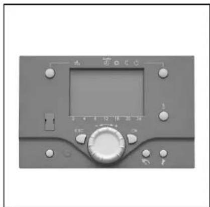
natural_image
Front view of a gray industrial control panel with digital display and rotary knob (no visible text or symbols)
Basisprincipes
Legenda:
Programmering
line
| T | Bx | On | Off |
|------|------|------|------|
| Low | Low | Low | Low |
| Peak | High | Low | Low |
| Mid | Low | Low | Low |
| Final| High | Low | Low |
Tapwater separaat circuit
Sturing ketelpomp/Tapw UV
2. Pomptrap Q21, Q22, Q23
Opnemertype collector