R3500 - Central heating boiler Elco - Free user manual and instructions
Find the device manual for free R3500 Elco in PDF.

| Brand | Elco |
| Model | R3500 |
| Product type | Condensing central heating boiler |
| Nominal useful output (80-60°C) | From 63 to 1001 kW depending on variant (R3501-R3505) |
| Nominal useful output (40/30°C) | From 624 to 1018 kW depending on variant |
| Efficiency at 80/60°C | 93.8 % |
| Efficiency at 40/30°C | 95.5 % |
| Electrical supply | 400 V / 50 Hz, mains fuse 16-20 A |
| Maximum gas pressure | 100 mbar |
| Maximum water temperature (upper limit) | 100 °C |
| Nominal water flow (dT=20K) | 26.4 to 43.0 m³/h depending on variant |
| Hydraulic pressure max/min | 8 / 1 bar |
| Dimensions (W x D x H) R3501 | 2265 x 1330 x 1355 mm |
| Weight (empty) R3501 | 740 kg |
| Weight (empty) R3505 | 1200 kg |
| Sound level at 1 m | 64 dB(A) |
| Protection rating | IP20 |
| Gas connection | R 2" (R3501) or DN65 PN16 (R3504-R3505) |
| Water connection | DN65 PN16 (R3501) or DN80 PN16 (R3503-R3505) |
| Flue gas connection | Diameter 300 to 400 mm depending on variant |
| Condensate connection | 40 mm |
| Maintenance | Mandatory annual inspection by qualified personnel; cleaning of siphon and condensate container |
| Safety | Temperature sensor, flow switch, minimum gas pressure switch, ionization electrode, temperature limit |
| Spare parts | Ignition and ionization electrodes, gas valves, heat exchangers, etc.; use only original parts |
Frequently Asked Questions - R3500 Elco
User questions about R3500 Elco
0 question about this device. Answer the ones you know or ask your own.
Ask a new question about this device
Download the instructions for your Central heating boiler in PDF format for free! Find your manual R3500 - Elco and take your electronic device back in hand. On this page are published all the documents necessary for the use of your device. R3500 by Elco.
USER MANUAL R3500 Elco
Operation and Installation manual for authorized technicians only

| Contents | 2 |
| Safety | General regulation...3 Application...3 Norms and regulations...3 |
| Construction | Layout of boiler...4 Operating principle...4 |
| Technical data | 5 |
| Extent of delivery | Standard boiler...15 Accessories...15 |
| Installation | Transport...16 Removing the casing...18 Boiler installation...19 Connecting the boiler...20 |
| Commissioning | Water and hydraulic system...22 Gas supply...23 Condensate connection...23 Flue and air intake connections...23 Prepare boiler for first startup...24 Combustion analysis...25 Air pressure switch...26 Check water flow...27 Check functionality of safety devices...28 Gas tightness check...28 Boiler shut down...28 Commissioning protocol...29 |
| Operating instructions | Main menu (operating mode) ...30 Parameter menu(information/programming mode) ...30 Changing parameter values ...30 |
| Maintenance | Checklist...31 Replacing the electrodes...31 Cleaning the condensate receptacle...32 Cleaning and refilling the syphon...32 Water pressure and quality...32 Water flow rate...32 Combustion analysis...32 Gas pressure...32 Gas tightness check...32 Safety devices...32 Maintenance protocol...33 |
| Lockouts | 34 |
| Sensor values | 36 |
| Declaration of Conformity | 37 |
General regulations Application Norms and regulations
General regulations
This documentation contains important information, which is a base for safe and reliable installation, commissioning and operation of the R3400/R3500/ R3600 boiler. All activities described in this document may only be executed by authorized companies.
Changes to this document may be effected without prior notice. We accept no obligation to adapt previously delivered products to incorporate such changes.
Only original spare parts may be used when replacing components on the boiler, otherwise warranty will be void.
Application
The R3400/R3500/R3600 boiler may be used for heating and hot water production purposes only. The boiler should be connected to closed systems with a maximum temperature of 100^ (high limit temperature), maximum setpoint temperature is 90^ .
Norms and regulations
When installing and operating the R3400/R3500/R3600 boiler, all applicable norms (european and local) should be fulfilled:
- Local building regulations for installing combustion air and flue gas systems;
- Regulation for connecting the boiler to the electrical appliance;
Regulations for connecting the boiler to the local gas network; - Norms and regulations according to safety equipment for heating systems;
- Any additional local laws/regulations with regard to installing and operating heating systems.
The R3400/R3500/R3600 boiler is CE approved and applies to the following European standards:
-92/42/EEC
Boiler efficiency directive
-90/396/EEC
Gas appliance directive
-73/23/EEC
Low voltage directive
-89/336/EEC
EMC directive
-EN656
Gas-fired central heating boilers - Type B boilers of nominal heat input exceeding 70kW but not exceeding 300 kW
-EN15417
Gas-fired central heating boilers - Specific requirements for condensing boilers with a nominal heat input greater than 70kW but not exceeding 1000 kW
-EN13836
Gas fired central heating boilers - Type B boilers of nominal heat input exceeding 300 kW, but not exceeding 1000 kW
- EN 15502-1
Gas-fired central heating boilers - Part 1: General requirements and tests
-EN55014-1
Electromagnetic compatibility - Requirements for household appliances, electric tools and similar apparatus - Part 1: Emission
- EN 55014-2
Electromagnetic compatibility - Requirements for household appliances, electric tools and similar apparatus - Part 2: Immunity - Product family standard
- EN 61000-3-2
Electromagnetic compatibility (EMC) - Part 3-2: Limits - Limits for harmonic current emissions (equipment input current 16 A per phase)
- EN 61000-3-3
Electromagnetic compatibility (EMC) - Part 3-3: Limitation of voltage changes, voltage fluctuations and flicker in public low-voltage supply systems, for equipment with rated current 16 A per phase and not subject to conditional connection
- EN 60335-1
Household and similar electrical appliances - Safety - Part 1: General requirements
-EN50165
Household and similar electrical appliances - Safety - Part 2-102: Particular requirements for gas, oil and solid-fuel burning appliances having electrical connections
Additional national standards
Germany:
RAL- UZ 61/DIN 4702-8
Switzerland:
Layout of boiler Operating principle
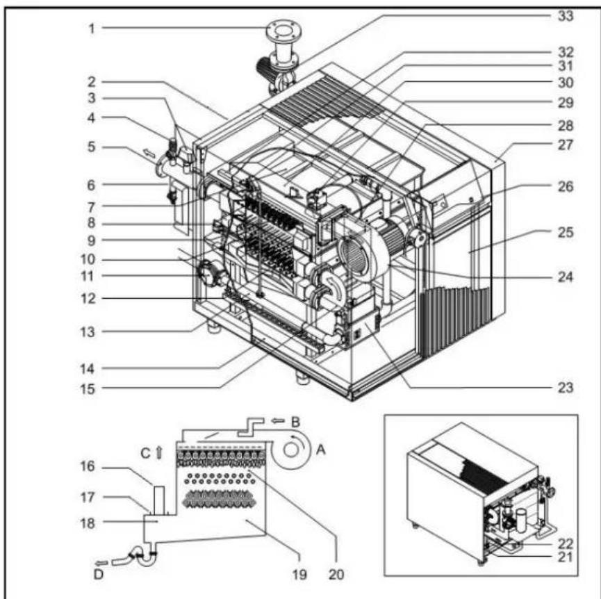
Layout of boiler
The R3400/R3500/R3600 boiler consists of the following main components:
1 Return water connection
2 Flue gas connection
3 Water flow switch
4 Safety valve
5 Flow water connection
6 Filling/draining valve
7 Top plate
8 Plenum
9 Burner
10 1st Heat exchanger
11 Gas filter
12 2nd Heat exchanger
13 Gastrain
14 Frame
15 180^ Bend
16 Compensator
17 Flue gas connection
18 Condensate receptacle
19 Flue gas receptacle
20 Combustion chamber
21 Entry electrical connections
22 Syphon
23 Main gas valve
24 Fan
25 Electrical box
26 Control panel
27 Casing
28 Air inlet damper
29 Butterfly valve
30 Main mixing channel
31 Pilot gas valve
32 Pilot mixing channel
33 Boiler pump
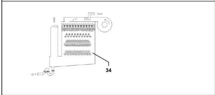
34 3rd Heat exchanger (only R3600)
A Air
B Gas
C Flue gasses
D Condensate
Operating principle
The R3400/R3500/R3600 is a fully modulating boiler. The control unit of the boiler adapts the modulation ratio automatically to the heat demand requested by the system. This is done by controlling the speed of the fan. As a result, the Whirlwind mixing system will adapt the gas ratio to the chosen fan speed, in order to maintain the best possible combustion figures and therewith the best efficiency. The flue gases created by the combustion are transported downwards through
the boiler and leave at the back side into the chimney connection.
The return water from the system enters the boiler in the lower section, where is the lowest flue gas temperature in the boiler. In this section condensation takes place. The water is being transported upwards through the boiler, in order to leave the boiler at the top (burner) section. The cross flow working principle (water up, flue gas down) ensures the most efficient combustion results.
The KM628 control unit can control the boiler operation based on:
- fixed temperature (stand alone operation);
- weather compensated operation (with optional controller);
with 0-10V external influence (temperature or capacity) from a building management system.
Technical data R3401 - R3405
| R3401 | R3402 | R3 | |||||
| Nominal heat output at 80-60°C max/min kW 656 | 164 | 733/183 | 857/213 | 971/242 | 1084/270 | ||
| Nominal heat output at 75-60°C max/min kW 657 | 164 | 734/183 | 858/213 | 972/242 | 1085/270 | ||
| Nominal heat output at 40/30°C max/min kW 663 | 181 | 741/202 | 867/236 | 981/268 | 1095/298 | ||
| Nominal heat input Hi max/min* kW 702/176 | 784/196 | 917/229 | 1038/260 | 1159/290 | |||
| Efficiency at 80/60°C % | 93.5 | ||||||
| Efficiency at 40/30°C % | 94.5 | ||||||
| Annual efficiency (NNG 75/60°C) % | 100.0 | ||||||
| Annual efficiency (NNG 40/30°C) % | - | ||||||
| Standstill losses (Twater = 70°C) | % | 0.2 | |||||
| Max. condensate flow | l/h | - | |||||
| Gas consumption H-gas max/min (10,9 kWh/m3) | m3/h | 64.5/16.2 | 71.9/18.0 | 84.1/21.0 | 95.2/23 | 8 | 106.3 |
| Gas consumption L-gas max/min (8,34 kWh/m3) | m3/h | 84.3/21.1 | 94.0/23.5 | 109.9/27.4 | 124.4/31 | 2 | 139.0 |
| Gas consumption LPG. max/min (12,8 kWh/kg) | kg/h | 54.9/13.8 | 61.2/15.3 | 71.6/17.9 | 81.1/20.3 | 90.5/22.6 | |
| Gas pressure H-gas | mbar | 20 | 35 | ||||
| Gas pressure L/LL-gas | mbar | 25 | 35 | ||||
| Gas pressure LPG | mbar | 30/50 | |||||
| Maximum gas pressure | mbar | 100 | |||||
| Flue gas temperature at 80/60°C max/min | °C | 165/70 | |||||
| Flue gas temperature at 40/30°C max/min | °C | 135/60 | |||||
| Flue gas quantity max/min* | m3/h | 1423/356 | 1580/395 | 1848/462 | 2091/523 | 2334/584 | |
| CO2level main burner natural gas H/E/L/LL max/min | % | 10.0/9.3 | |||||
| CO2level main burner liquid gas P max/min | % | 11.0/11.0 | |||||
| CO2level pilot burner natural gas H/E/L/LL max/min | % | 10.0/10.2 | |||||
| CO2level pilot burner liquid gas P max/min | % | 11.0/11.2 | |||||
| NOx level max/min | mg/kWh | 61.4/22.0 | |||||
| CO level max/min mg/kWh | 9.8/3.3 | ||||||
| Max. permissible flue resistance max/min | Pa | 150 | |||||
| Water volume | I | 50 | 53 | 70 | 75 | 80 | |
| Water pressure max/min | bar | 8/1 | |||||
| Max. water temperature (High limit thermostat) | °C | 100 | |||||
| Maximum temperature setpoint | °C | 90 | |||||
| Nominal water flow at dT=20K | m3/h | 28.5 | 31.6 | 37.0 | 41.8 | 46.8 | |
| Hydraulic resistance at nominal water flow | kPa | 46 | 53 | 36 | 43 | 50 | |
| Electrical connection | V | 400 | |||||
| Frequency | Hz | 50 | |||||
| Mains connection fuse | A | 16 | 20 | ||||
| IP class | - | IP20 | |||||
| Power consumption boiler (excl. pump) | W | 900 | 900 | 1270 | 1270 | 1270 | |
| Power consumption 3-step pump (optional) | W | 980 | 1010 | 1020 | 1450 | 1500 | |
| Weight (empty) | kg | 675 | 740 | 840 | 950 | 1070 | |
| Noise level at 1 meter distance | dB(A) | 64 | |||||
| Ionisation current minimum | μA | 6 | |||||
| PH value condensate | - | 3.2 | |||||
| CE certification code | - | CE-0063AR3514 | |||||
| Water connections | - | DN65 PN16 | DN80 PN16 | ||||
| Gas connection | - | R 2" | DN65 PN16 | ||||
| Flue gas connection | mm | 300 | 350 | 400 | |||
| Air intake connection (for room sealed use) | mm | 250 | 300 | 355 | |||
| Condensate connection | mm | 40 | |||||
Technical R3406 - R3410
| R3406 | R3407 | |||||
| Nominal heat output at 80-60°C max/min kW 1196/298 | 309/326 | 1496/373 | 1683/419 | 1870/466 | ||
| Nominal heat output at 75-60°C max/min kW 1197/298 | 310/326 | 1498/373 | 1685/419 | 1872/466 | ||
| Nominal heat output at 40/30°C max/min kW 1209/329 | 323/360 | 1512/412 | 1701/463 | 1890/515 | ||
| Nominal heat input Hi max/min* kW 1279/320 | 1400/350 | 1600/400 | 1800/450 | 200/500 | ||
| Efficiency at 80/60°C % | 93.5 | |||||
| Efficiency at 40/30°C % | 94.5 | |||||
| Annual efficiency (NNG 75/60°C) % | 100.0 | |||||
| Annual efficiency (NNG 40/30°C) % | - | |||||
| Standstill losses (Twater = 70°C) % | 0,2 | |||||
| Max. condensate flow | l/h | - | ||||
| Gas consumption H-gas max/min (10,9 kWh/m3) | m3/h | 117.3/29.3 | 128.4/32.1 | 146.7/36.7 | 165.1/41.3 | |
| Gas consumption L-gas max/min (8,34 kWh/m3) | m3/h | 153.4/38.4 | 167.9/42.0 | 191.8/48.0 | 215.8/54.0 | |
| Gas consumption LPG. max/min (12,8 kWh/kg) | kg/h | 99.9/25.0 | 108.7/27.2 | 124.3/31.1 | 139.8/35.0 | |
| Gas pressure H-gas | mbar | 35 | 50 | |||
| Gas pressure L/LL-gas | mbar | 35 | 50 | |||
| Gas pressure LPG | mbar | 30/50 | 50 | |||
| Maximum gas pressure | mbar | 100 | ||||
| Flue gas temperature at 80/60°C max/min | °C | 165/70 | ||||
| Flue gas temperature at 40/30°C max/min | °C | 135/60 | ||||
| Flue gas quantity max/min* | m3/h | 2578/645 | 2825/706 | 3227/807 | 3631/908 | |
| CO2level main burner natural gas H/E/L/LL max/min | % | 10.0/9.3 | ||||
| CO2level main burner liquid gas P max/min | % | 11.0/11.0 | ||||
| CO2level pilot burner natural gas H/E/L/LL max/min | % | 10.0/10.2 | ||||
| CO2level pilot burner liquid gas P max/min | % | 11.0/11.2 | ||||
| NOx level max/min | mg/kWh | 61.4/22.0 | ||||
| CO level max/min mg/kWh | 9.8/3.3 | |||||
| Max. permissible flue resistance max/min | Pa | 150 | ||||
| Water volume | I | 85 | 97 | 109 | 116 | |
| Water pressure max/min | bar | 8/1 | ||||
| Max. water temperature (High limit thermostat) | °C | 100 | ||||
| Maximum temperature setpoint | °C | 90 | ||||
| Nominal water flow at dT=20K | m3/h | 51,6 | 56,1 | 64,1 | 72,1 | |
| Hydraulic resistance at nominal water flow | kPa | 58 | 91 | 60 | 130 | |
| Electrical connection | V | 400 | ||||
| Frequency | Hz | 50 | ||||
| Mains connection fuse | A | 20 | C25 | |||
| IP class | - | IP20 | ||||
| Power consumption boiler (excl. pump) | W | 1270 | 1910 | 2330 | 2520 | |
| Power consumption 3-step pump (optional) | W | 1500 | 4000 | 7500 | ||
| Weight (empty) | kg | 1200 | 1210 | 1525 | 1665 | |
| Noise level at 1 meter distance | dB(A) | 64 | ||||
| Ionisation current minimum | μA | 6 | ||||
| PH value condensate | - | 3.2 | ||||
| CE certification code | - | CE-0063AR3514 | ||||
| Water connections | - | DN80 PN16 | DN80 PN16 | |||
| Gas connection | - | DN65 PN16 | DN80 PN16 | |||
| Flue gas connection | mm | 400 | 450 | 500 | ||
| Air intake connection (for room sealed use) | mm | 355 | - | |||
| Condensate connection | mm | 40 | ||||
R3408
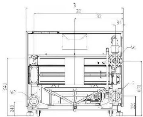
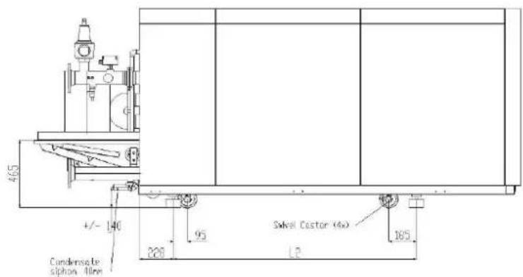
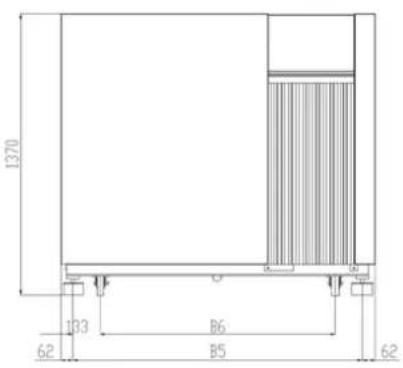
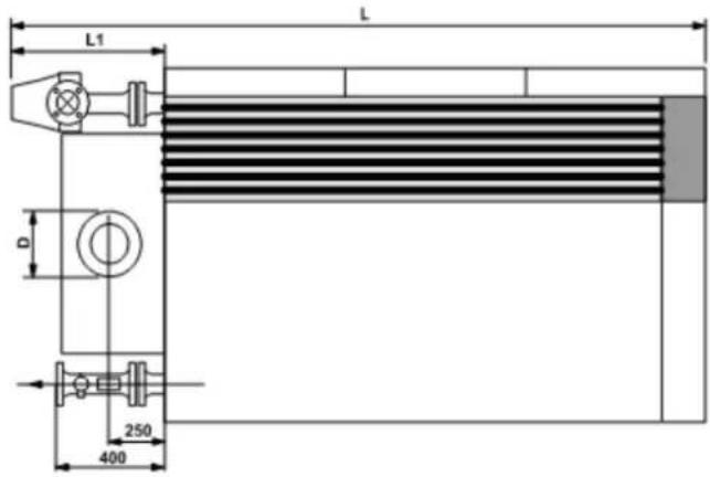
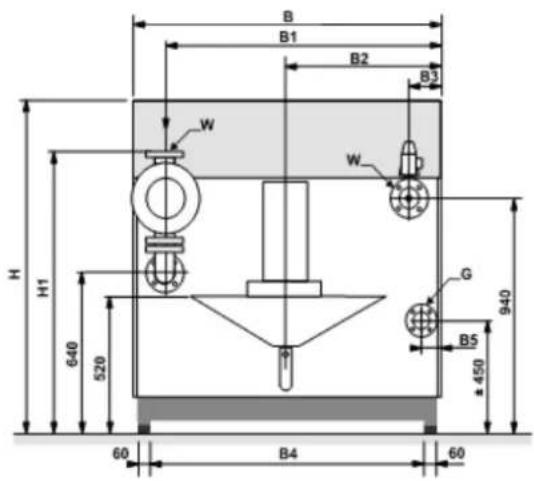
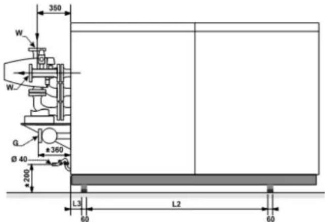
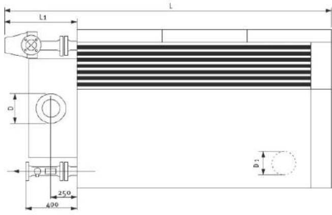
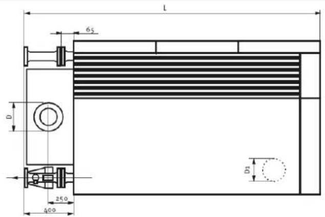
Dimensions R3401 - R3406
| Dimensions | R3401 | R3402 | R3403 | R3404 | R3405 | R3406 58 770 1166 1166 | |
| L | mm | 2265 | 2265 | 2653 | 2653 | 2658 | 26 |
| L1 | mm | 595 | 595 | 610 | 615 | 615 | 88 1166 1166 |
| L2 | mm | 700 | 700 | 1166 | 1166 | ||
| L3 | mm | 108 | 108 | 88 | 88 | 88 | |
| H | mm | 1355 | 1355 | 1355 | 1355 | 1355 | |
| H1 | mm | 1125 | 1125 | 1570 | 1420 | 1155 | |
| B | mm | 1330 | 1330 | 1130 | 1130 | 1330 | |
| B1 | mm | 1160 | 1210 | 1003 | 1053 | 1203 | |
| B2 | mm | 665 | 665 | 565 | 565 | 665 | |
| B3 | mm | 170 | 120 | 127 | 77 | ||
| B4 | mm | 1146 | 1146 | 946 | 946 | 1146 | |
| B5 | mm | 115 | 65 | 115 | 65 | 115 | 65 |
| D | mm | 300 | 350 | 350 | 400 | 400 | |
| W | DN | DN65 PN16 | DN65 PN16 | DN80 PN16 | DN80 PN16 | DN80 PN16 | |
| G | R | R 2" | R 2" | R 2" | R 2" | DN65 PN16 | DN65 PN16 |
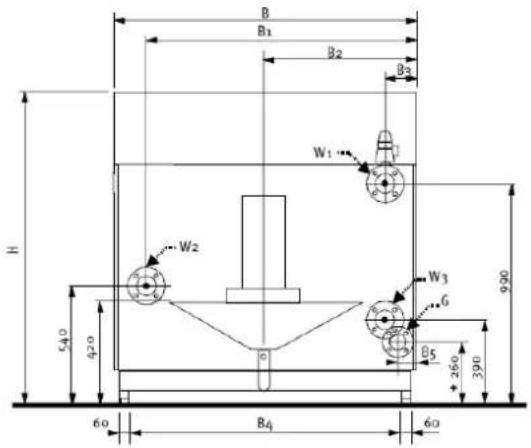
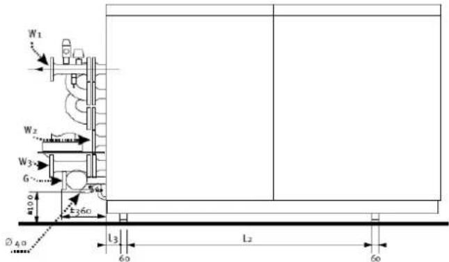
Dimensions R3407 - R3410
R3407 - R3408
R3409-R3410
| Dimensions | R3407 | R3408 | R3409 | R3410 | |
| L | mm | 27 | 55 | 32 | 65 |
| L2 | mm | 1 | 120 | 1 | 630 |
| B | mm | 15 | 30 | 13 | 30 |
| B2 | mm | 1407 | 1 | 207 | 1 |
| B3 | mm | 765 | 665 | 765 | 765 |
| B4 | mm | 12 | 6.5 | 12 | 6.5 |
| B5 | mm | 1406 | 1 | 206 | 1 |
| B6 | 11 | 40 | 94 | 0 | 11 |
| D | mm | 450 | 450 | 500 | 500 |
| W1 | DN | DN80 PN16 | DN80 PN16 | DN80 PN16 | DN80 PN16 |
| W2 | DN | DN80 PN16 | DN80 PN16 | DN80 PN16 | DN80 PN16 |
| G | DN | DN65 PN16 | DN65 PN16 | DN80 PN16 | DN80 PN16 |
Technical data R3501 - R3505
| R3501 | R3502 | |||||
| Nominal heat output at 80-60°C max/min kW 613 | 175 | 717/204 | 811/231 | 906/258 | 1000/285 | |
| Nominal heat output at 75-60°C max/min kW 613 | 175 | 717/204 | 812/231 | 907/258 | 1001/285 | |
| Nominal heat output at 40/30°C max/min kW 624 | 195 | 730/228 | 826/258 | 923/288 | 1018/319 | |
| Nominal heat input Hi max/min* kW 653/187 | 764/218 | 865/247 | 966/276 | 1066/305 | ||
| Efficiency at 80/60°C % | 93.8 | |||||
| Efficiency at 40/30°C % | 95.5 | |||||
| Annual efficiency (NNG 75/60°C) % | 102.2 | |||||
| Annual efficiency (NNG 40/30°C) % | - | |||||
| Standstill losses (Twater = 70°C) % | 0.3 | |||||
| Max. condensate flow l/h | - | |||||
| Gas consumption H-gas max/min (10,9 kWh/m3) | m3/h | 59.9/17.1 | 70.1/20.0 | 79.4/22.7 | 88.6/25 | 3 97.8/27 |
| Gas consumption L-gas max/min (8,34 kWh/m3) | m3/h | 78.3/22.4 | 91.6/26.2 | 103.7/29.6 | 115.8/33.1 | 127.8/36.5 |
| Gas consumption LPG. max/min (12,8 kWh/kg) | kg/h | 51.0/14.6 | 59.7/17.1 | 67.6/19.3 | 75.5/21.6 | 83.3/23.8 |
| Gas pressure H-gas | mbar | 20 | ||||
| Gas pressure L/LL-gas | mbar | 25 | ||||
| Gas pressure LPG | mbar | 30/50 | ||||
| Maximum gas pressure | mbar | 100 | ||||
| Flue gas temperature at 80/60°C max/min | °C | 155/65 | ||||
| Flue gas temperature at 40/30°C max/min | °C | 120/55 | ||||
| Flue gas quantity max/min* | m3/h | 1287/368 | 1505/430 | 1703/487 | 1901/543 | 2099/60 |
| CO2level main burner natural gas H/E/L/LL max/min | % | 10.0/9.3 | ||||
| CO2level main burner liquid gas P max/min | % | 11.0/11.0 | ||||
| CO2level pilot burner natural gas H/E/L/LL max/min | % | 10.0/10.2 | ||||
| CO2level pilot burner liquid gas P max/min | % | 11.0/11.2 | ||||
| NOx level max/min mg/kWh | 11.5/19.5 | |||||
| CO level max/min mg/kWh | 27.3/6.5 | |||||
| Max. permissible flue resistance max/min | Pa | 150 | ||||
| Water volume | I | 53 | 70 | 75 | 80 | 85 |
| Water pressure max/min | bar | 8/1 | ||||
| Max. water temperature (High limit thermostat) | °C | 100 | ||||
| Maximum temperature setpoint | °C | 90 | ||||
| Nominal water flow at dT=20K | m3/h | 26.4 | 30.8 | 34.9 | 39.0 | 43.0 |
| Hydraulic resistance at nominal water flow | kPa | 37 | 25 | 30 | 35 | 40 |
| Electrical connection | V | 400 | ||||
| Frequency | Hz | 50 | ||||
| Mains connection fuse | A | 16 | 20 | |||
| IP class | - | IP20 | ||||
| Power consumption boiler max/min (excl. pump) | W | 900 | 1270 | |||
| Power consumption 3-step pump (optional) | W | 960 | 1000 | 1020 | 1400 | 1500 |
| Power consumption speed controlled pump (optional) | W | 394 | 375 | 523 | 557 | |
| Weight (empty) | kg | 740 | 840 | 950 | 1070 | 1200 |
| Noise level at 1 meter distance | dB(A) | 64 | ||||
| Ionisation current minimum | μA 6 | |||||
| PH value condensate | - 3.2 | |||||
| CE certification code | - | CE-0063AR3514 | ||||
| Water connections | - | DN65 PN16 | DN80 PN16 | |||
| Gas connection | - | R 2" | DN65 PN16 | |||
| Flue gas connection | mm | 300 | 350 | 400 | ||
| Air intake connection (for room sealed use) | mm | 250 | 300 | 355 | ||
| Condensate connection | mm | 40 | ||||
R3503
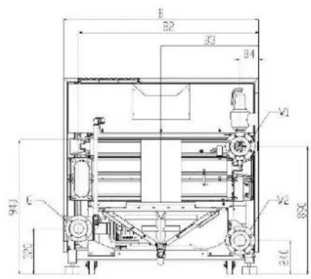
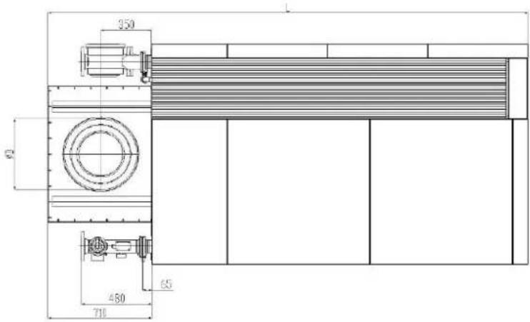
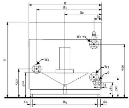
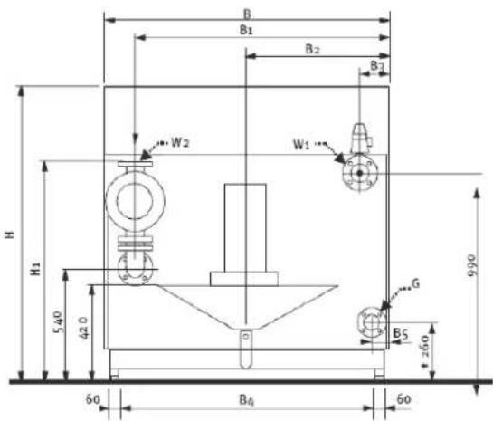
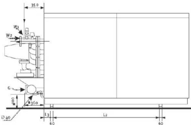
Dimensions R3501 - R3505
| Dimensions | R3501 | R3502 | R3503 | R3504 | R3505 | |
| L | mm | 2265 | 2653 | 2653 | 2658 | 2658 |
| L1 | mm | 595 | 610 | 610 | 615 | |
| L2 | mm | 700 | 1166 | 1166 | 1166 | 1166 |
| L3 | mm | 108 | 88 | 88 | 88 | 88 |
| H | mm 1355 | 1355 | 1355 | 1355 | 1355 | |
| H1 | mm 1125 | 1400 | 1400 | 1155 | 1155 | |
| B | mm 1330 | 1130 | 130 | 1330 | 1330 | |
| B1 | mm 1210 | 1003 | 1053 | 1203 | 1253 | |
| B2 | mm | 665 | 565 | 565 | 665 | 665 |
| B3 | mm | 120 | 127 | 77 | 127 | 77 |
| B4 | mm | 1146 | 946 | 946 | 1146 | 1146 |
| B5 | mm | 65 | 115 | 65 | 115 | 65 |
| D | mm 300 | 350 | 350 | 400 | 400 | |
| W | DN | DN65 PN16 | DN80 PN16 | DN80 PN16 | DN80 PN16 | DN80 PN16 |
| G | R | R 2" | R 2" | R 2" | DN65 PN16 | DN65 PN16 |
Technical data R3600 - R3605 Standard
| R3600 | R3601 | R3602 | R3603 | R3604 | R3605 | ||
| Nominal heat output at 80-60°C max/min kW 572/142 | 639/182 | 747/212 | 846/241 | 945/269 | 1043/297 | ||
| Nominal heat output at 75-60°C max/min kW 576/144 | 643/184 | 753/215 | 852/243 | 952/272 | 1050/300 | ||
| Nominal heat output at 40/30°C max/min kW 602/159 | 672/203 | 786/237 | 890/268 | 994/300 | 1097/31 | ||
| Nominal heat input Hi max/min* kW 585/146 | 653/187 | 764/218 | 865/247 | 966 | 1066/305 | ||
| Efficiency at 80/60°C % | 97.8 | ||||||
| Efficiency at 40/30°C % | 102.9 | ||||||
| Annual efficiency (NNG 75/60°C) % | 105,1 | ||||||
| Annual efficiency (NNG 40/30°C) % | 109,8 | ||||||
| Standstill losses (Twater = 70°C) % | 0,3 | ||||||
| Max. condensate flow | l/h | - | |||||
| Gas consumption H-gas max/min (10,9 kWh/m3) | m3/h | 53.7/13.4 | 59.9/17.1 | 70.1/20.0 | 79.4/22.7 | 88.6 | 25.3 97 |
| Gas consumption L-gas max/min (8,34 kWh/m3) | m3/h | 70.3/17.6 | 78.3/22.4 | 91.6/26.2 | 103.7/29.6 | 115.8/33.1 | 127.8/36.5 |
| Gas consumption LPG. max/min (12,8 kWh/kg) | kg/h | 45.7/11.4 | 51.0/14.6 | 59.7/17.1 | 67.6/19.3 | 75.5/21.6 | 83.3/23.8 |
| Gas pressure H-gas | mbar | 20 | |||||
| Gas pressure L/LL-gas | mbar | 25 | |||||
| Gas pressure LPG | mbar | 30/50 | |||||
| Maximum gas pressure | mbar | 100 | |||||
| Flue gas temperature at 80/60°C max/min | °C | 85/65 | |||||
| Flue gas temperature at 40/30°C max/min | °C | 59/36 | |||||
| Flue gas quantity max/min* | m3/h | 969/242 | 1076/307 | 1258/359 | 1424/407 | 1590/454 | 1756/502 |
| CO2 level main burner natural gas H/E/L/LL max/min | % | 10.0/9.3 | 10.0/9.3 | ||||
| CO2 level main burner liquid gas P max/min | % | 11.0/11.0 | 11.0/11.0 | ||||
| CO2 level pilot burner natural gas H/E/L/LL max/min | % | - | 10.0/10.2 | ||||
| CO2 level pilot burner liquid gas P max/min | % | - | 11.0/11.2 | ||||
| NOx level max/min | mg/kWh | 32.3/18.8 | 11.5/19.5 | ||||
| CO level max/min mg/kWh 8.2/10.9 | 27.3/6.5 | ||||||
| Max. permissible flue resistance max/min | Pa | 100 | 150 | ||||
| Water volume | I | 69 | 73 | 97 | 104 | 110 | 117 |
| Water pressure max/min | bar | 8/1 | |||||
| Max. water temperature (High limit thermostat) | °C | 100 | |||||
| Maximum temperature setpoint | °C | 90 | |||||
| Nominal water flow at dT=20K | m3/h | 24,7 | 27,6 | 32,2 | 36,5 | 40,8 | 45,0 |
| Hydraulic resistance at nominal water flow | kPa | 48 | 56 | 38 | 45 | 53 | 60 |
| Electrical connection | V | 400 | |||||
| Frequency | Hz | 50 | |||||
| Mains connection fuse | A | 10 | 16 | 20 | |||
| IP class | - | IP20 | |||||
| Power consumption boiler (excl. pump) | W | 420 | 900 | 1270 | |||
| Power consumption 3-step pump (optional) | W | 940 | 980 | 1020 | 1400 | 1450 | 1500 |
| Power consumption speed controlled pump (optional) | W | 471 | 616 | 561 | 661 | 867 | 956 |
| Weight (empty) | kg | 810 | 890 | 1040 | 1150 | 1280 | 1410 |
| Noise level at 1 meter distance | dB(A) | 64 | |||||
| Ionisation current minimum | μA | 6 | |||||
| PH value condensate | - | 3.2 | |||||
| CE certification code | - | CE-0063AR3514 | |||||
| Water connections | - | DN65 PN16 | DN80 PN16 | ||||
| Gas connection | - | R 2" | DN65 PN16 | ||||
| Flue gas connection | mm | 300 | 350 | 400 | |||
| Air intake connection (for room sealed use) | mm | 250 | 300 | 355 | |||
| Condensate connection | mm | 40 | |||||
Dimensions R3600 - R3605 Standard
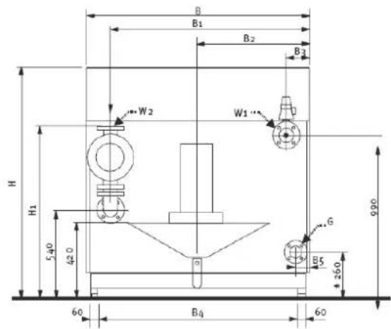
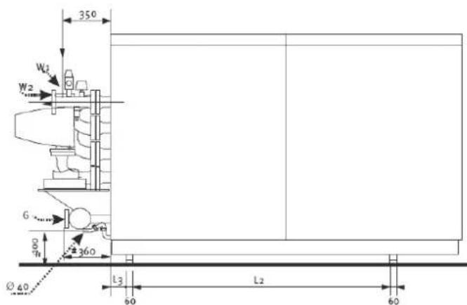
| Dimensions | R36001 | R3602 | R3603 | R3604 | R3605 | |
| L mm | 1958 | 2265 | 2653 | 2653 | 2658 | |
| L1 | mm595 | 595 | 610 | 610 | 615 | |
| L2 | mm 700 | 590 | 1166 | 1166 | 1166 | |
| L3 mm | 108 | 198 | 88 | 88 | ||
| H mm | 1355 | 1405 | 1405 | 1405 | 1405 | |
| H1 mm | 970 | 1175 | 1450 | 1450 | 1205 | |
| B mm | 1230 | 1330 | 1130 | 1130 | 1330 | |
| B1 mm | 1110 | 1210 | 1003 | 1053 | 1203 | |
| B2 mm | 615 | 665 | 565 | 565 | 665 | |
| B3 mm | 120 | 120 | 127 | 77 | 77 | |
| B4 mm | 1046 | 1146 | 946 | 946 | 1146 | |
| B5 mm | 100 | 65 | 115 | 65 | 115 | |
| D mm | 300 | 300 | 350 | 350 | 400 | |
| D1 mm | 250 | 250 | 300 | 300 | 355 | |
| W1 DN | DN65 PN16 | DN65 PN16 | DN80 PN16 | DN80 PN16 | DN80 PN16 | DN80 PN16 |
| W2 DN | DN65 PN16 | DN65 PN16 | DN80 PN16 | DN80 PN16 | DN80 PN16 | DN80 PN16 |
| G R | R 2" | R 2" | R 2" | R 2" | DN65 PN16 | DN65 PN16 |
2658
1166
88
1405
1427
1330
1253
665
65
400
355
Technical data R3600 - R3605 Split system
| R3600 | R3601 | R3602 | R3603 | R3604 | R3605 | ||
| Nominal heat output at 80-60°C max/min kW 572/142 | 639/182 | 747/212 | 846/241 | 945/269 | 1043/297 | ||
| Nominal heat output at 75-60°C max/min kW 576/144 | 643/184 | 753/215 | 852/243 | 952/272 | 1050/300 | ||
| Nominal heat output at 40/30°C max/min kW 602/159 | 672/203 | 786/237 | 890/268 | 994/300 | 1097/31 | ||
| Nominal heat input Hi max/min* kW 585/146 | 653/187 | 764/218 | 865/247 | 966/276 | 106/305 | ||
| Efficiency at 80/60°C % | 97.8 | ||||||
| Efficiency at 40/30°C % | 102.9 | ||||||
| Annual efficiency (NNG 75/60°C) % | 105,1 | ||||||
| Annual efficiency (NNG 40/30°C) % | 109,8 | ||||||
| Standstill losses (Twater = 70°C) % | 0,3 | ||||||
| Max. condensate flow | l/h | - | |||||
| Gas consumption H-gas max/min (10,9 kWh/m3) | m3/h | 53.7/13.4 | 59.9/17.1 | 70.1/20 | 79.4/22.7 | 88.6/25.3 | |
| Gas consumption L-gas max/min (8,34 kWh/m3) | m3/h | 70.3/17.6 | 78.3/22.4 | 91.6/26.2 | 103.7/29.6 | 115.8/33.1 | |
| Gas consumption LPG. max/min (12,8 kWh/kg) | kg/h | 45.7/11.4 | 51.0/14.6 | 59.7/17.1 | 67.6/19.3 | 75.5/21.6 | |
| Gas pressure H-gas | mbar | 20 | |||||
| Gas pressure L/LL-gas | mbar | 25 | |||||
| Gas pressure LPG | mbar | 30/50 | |||||
| Maximum gas pressure | mbar | 100 | |||||
| Flue gas temperature at 80/60°C max/min | °C | 85/65 | |||||
| Flue gas temperature at 40/30°C max/min | °C | 59/36 | |||||
| Flue gas quantity max/min* | m3/h | 969/242 | 1076/307 | 1258/359 | 1424/407 | 1590/454 | |
| CO2level main burner natural gas H/E/L/LL max/min | % | 10.0/9.3 | 10.0/9.3 | ||||
| CO2level main burner liquid gas P max/min | % | 11.0/11.0 | 11.0/11.0 | ||||
| CO2level pilot burner natural gas H/E/L/LL max/min | % | - | 10.0/10.2 | ||||
| CO2level pilot burner liquid gas P max/min | % | - | 11.0/11.2 | ||||
| NOx level max/min | mg/kWh | 32.3/18.8 | 11.5/19.5 | ||||
| CO level max/min mg/kWh 8.2/10.9 | 27.3/6.5 | ||||||
| Max. permissible flue resistance max/min | Pa | 100 | 150 | ||||
| Water volume | I | 73 | 97 | 104 | 110 | 117 | |
| Water pressure max/min | bar | 8/1 | |||||
| Max. water temperature (High limit thermostat) | °C | 100 | |||||
| Maximum temperature setpoint | °C | 90 | |||||
| Nominal water flow at dT=20K | m3/h | 24,7 | 27,6 | 32,2 | 36,5 | 40,8 | |
| Hydraulic resistance at nominal water flow | kPa | 48 | 56 | 38 | 45 | 53 | |
| Electrical connection | V | 400 | |||||
| Frequency | Hz | 50 | |||||
| Mains connection fuse | A | 10 | 16 | 20 | |||
| IP class | - | IP20 | |||||
| Power consumption boiler (excl. pump) | W | 730 | 900 | 1270 | |||
| Weight (empty) | kg | 810 | 890 | 1040 | 1150 | 1280 | |
| Noise level at 1 meter distance | dB(A) | 64 | |||||
| Ionisation current minimum | μA | 6 | |||||
| PH value condensate | - | 3.2 | |||||
| CE certification code | - | CE-0063AR3514 | |||||
| Water connections | - | DN65 PN16 | DN80 PN16 | ||||
| Gas connection | - | R 2" | DN65 PN16 | ||||
| Flue gas connection | mm | 300 | 350 | 400 | |||
| Air intake connection (for room sealed use) | mm | 250 | 300 | 355 | |||
| Condensate connection | mm | 40 | |||||
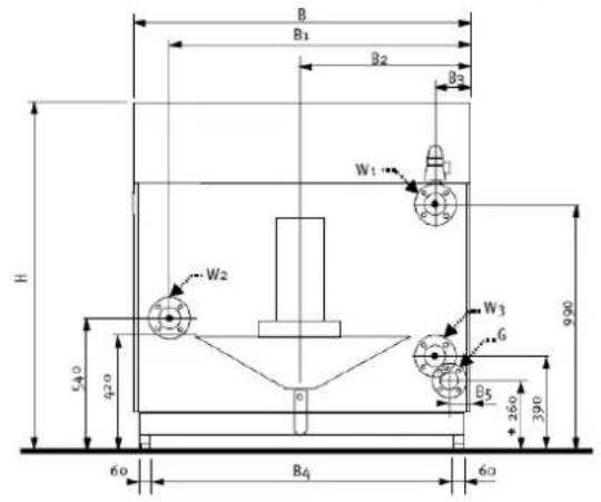
Dimensions R3600 - R3605 Split system

| Dimensions | R3600 | R3601 | R3602 | R3603 | R3604 | ||
| L | mm | 1958 | 2070 | 2443 | 2443 | ||
| L2 | mm | 700 | 590 | 1166 | 1166 | 1166 | |
| L3 | mm | 108 | 198 | 88 | 88 | 88 | 88 |
| H | mm | 1355 | 1405 | 1405 | 1405 | 1405 | 1405 |
| B | mm | 1230 | 1330 | 1130 | 1130 | 1330 | 1330 |
| B1 | mm | 1110 | 1210 | 1003 | 1053 | 1203 | 1253 |
| B2 | mm | 615 | 665 | 565 | 565 | 665 | 665 |
| B3 | mm | 120 | 120 | 127 | 77 | 127 | 77 |
| B4 | mm | 1046 | 1146 | 946 | 946 | 1146 | 1146 |
| B5 | mm | 100 | 65 | 115 | 65 | 115 | 65 |
| D | mm | 300 | 300 | 350 | 350 | 400 | 400 |
| D1 | mm | 250 | 250 | 300 | 300 | 355 | 355 |
| W1 | DN | DN65 PN16 | DN65 PN16 | DN80 PN16 | DN80 PN16 | DN80 PN16 | DN80 PN16 |
| W2 | DN | DN65 PN16 | DN65 PN16 | DN80 PN16 | DN80 PN16 | DN80 PN16 | DN80 PN16 |
| W3 | DN | DN65 PN16 | DN65 PN16 | DN80 PN16 | DN80 PN16 | DN80 PN16 | DN80 PN16 |
| G | R | R 2" | R 2" | R 2" | R 2" | DN65 PN16 | DN65 PN16 |
R3605
2443
1166
Extent of delivery
Standard boiler
Accessories
Standard boiler
A boiler delivery package contains the
following components:
| Component | Pcs. | Package |
| R3400/R3500/R3600 Boiler fully assembled and tested 1 Mo | ounted on | wooden blocks with wooden border, sealed in PE foil |
| Adjustable feet 4 Cardboard box on top of boiler | (on R3407-R3410 already fitted to boiler) | |
| Syphon for condensate connection 1 Cardboard box on top of heatex | change | (under casing) |
| Operation and Installation manual 1 Map attached to back panel of the boiler | ||
| Wiring diagram 1 Map attached to back panel of the boiler |
Accessories
On request it is possible to get various
options and/or accessories. Ask your
supplier for the possibilities.
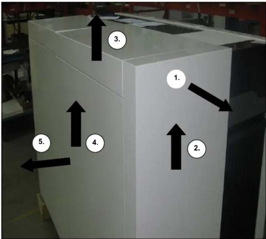
Transport
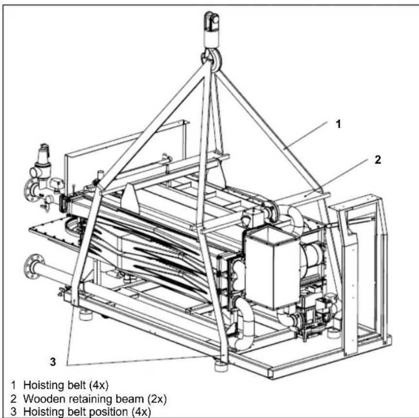
Boiler transport
The R3400/R3500/R3600 boiler will be supplied as a complete unit being fully assembled and pre-tested. The boiler can be transported with a pallet truck (at least 1m wide), picking the boiler up from the side.
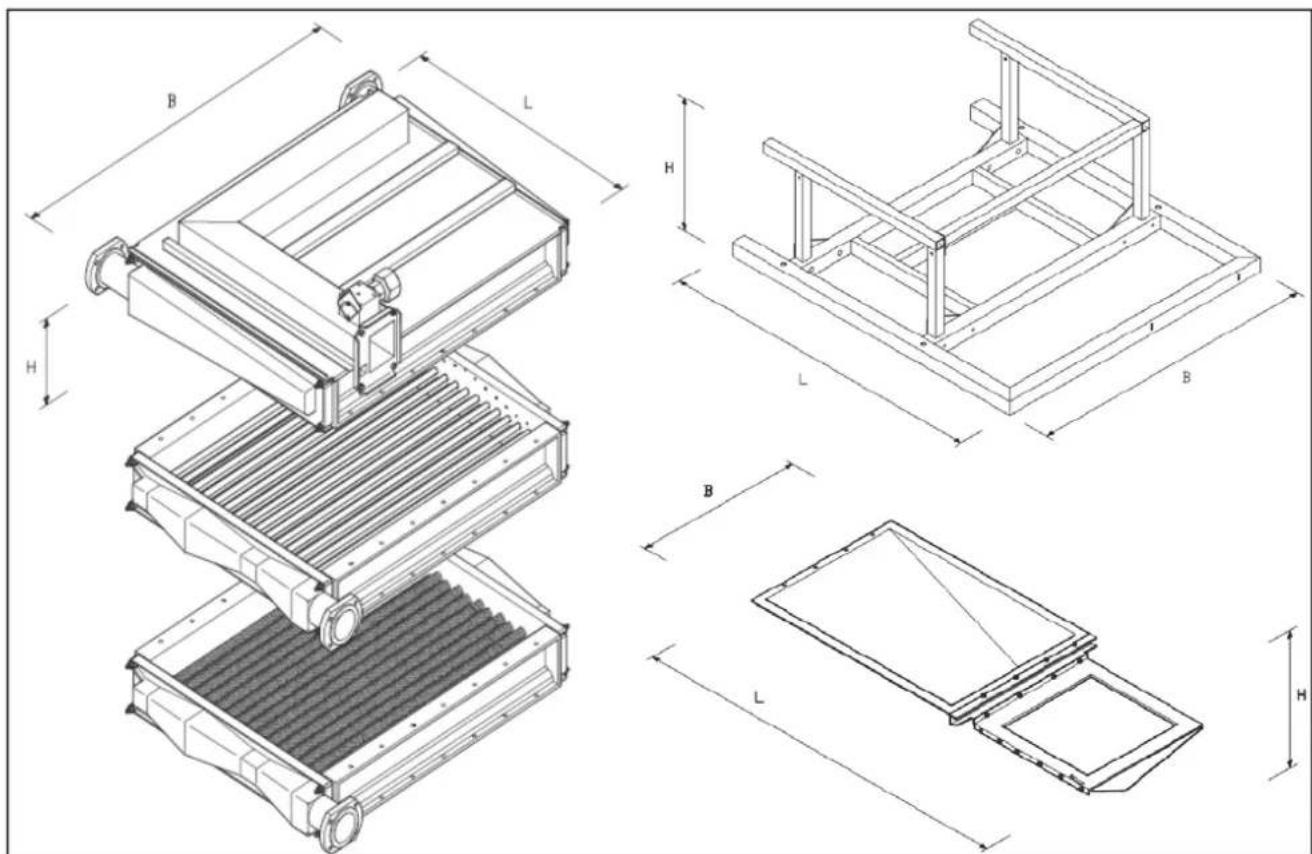
Whenever necessary, the boiler can be dismantled into smaller parts for easier transport inside the building. The table below shows the main dismantled parts with their weight and dimensions.
When the R3400/R3500/R3600 boiler has to be transported with a crane, it is necessary to remove the casing before connecting the boiler to the crane. Always connect the crane to the frame of the boiler by using straps.
| Component | R3600 | R340R3401 R3501 R3601 | R3403 R3502 R3602 | R3404 R3503 R3603 | R3405 R3504 R3604 | R3406 R3505 R3605 | ||
| Burner m [kg] | 135 | 135 | 140 | 210 | 215 | 220 | 225 | |
| L [mm] | 1010 | 1010 | 1010 | 1420 | 1420 | 1420 | 1420 | |
| W [mm] | 1150 | 1150 | 1310 | 1010 | 1110 | 1210 | 1310 | |
| H [mm] | 420 | 420 | 500 | 500 | 500 | 500 | 500 | |
| \( 1^{st}Heat exchanger m [kg] \) | 120 | 120 | 135 | 180 | 185 | 190 | 195 | |
| L [mm] | 1010 | 1030 | 1010 | 1420 | 1420 | 1420 | 1420 | |
| W [mm] | 1150 | 1150 | 1310 | 1010 | 1110 | 1210 | 1310 | |
| H [mm] | 160 | 150 | 160 | 160 | 160 | 160 | 160 | |
| \( 2^{nd}Heat exchanger \) | m [kg] | 135 | 135 | 150 | 200 | 200 | 210 | 210 |
| L [mm] | 1010 | 1030 | 1010 | 1420 | 1420 | 1420 | 1420 | |
| W [mm] | 1150 | 1050 | 1310 | 1010 | 1110 | 1210 | 1310 | |
| H [mm] | 160 | 150 | 160 | 160 | 160 | 160 | 160 | |
| \( 3^{rd}Heat exchanger (only R3600 series) \) | m [kg] | - | 135 | 150 | 200 | 200 | 210 | 210 |
| L [mm] | - | 1030 | 1010 | 1420 | 1420 | 1420 | 1420 | |
| W [mm] | - | 1050 | 1310 | 1010 | 1110 | 1210 | 1310 | |
| H [mm] | - | 150 | 160 | 160 | 160 | 160 | 160 | |
| Frame H for R3600 in ( ) | m [kg] | 50 | 50 | 60 | 70 | 70 | 70 | 70 |
| L [mm] | 1325 | 1325 | 1630 | 2004 | 2004 | 2004 | 2004 | |
| W [mm] | 1165 | 1165 | 1266 | 1066 | 1066 | 1266 | 1266 | |
| H [mm] | 460 | 360 | 500 (370) | 500 (370) | 500 (370) | 500 (370) | 500 (370) | |
| Condensate receptacle m | [kg] | < 25 | < 25 | < 25 | < 35 | < 35 | < 35 | < 35 |
| L [mm] | 1320 | 1320 | 1450 | 1950 | 1950 | 1950 | 1950 | |
| W [mm] | 990 | 990 | 1070 | 770 | 870 | 970 | 1070 | |
| H [mm] | 400 | 275 | 400 | 400 | 400 | 400 | 400 |
Transport
| Component | R3407 | ||||
| Burner m [kg] | 230 | 385 | 390 | 395 | |
| L [mm] | 1510 | 2050 | 2050 | 2050 | |
| B [mm] | 1400 | 1250 | 1350 | 1450 | |
| H [mm] | 600 | 600 | 620 | 620 | |
| \( 1^{st}Heat exchanger m [kg] \) | 200 | 325 | 330 | 335 | |
| L [mm] | 1510 | 2050 | 2050 | 2050 | |
| B [mm] | 1425 | 1250 | 1350 | 1450 | |
| H [mm] | 150 | 150 | 150 | 150 | |
| \( 2^{nd}Heat exchanger \) | m [kg] | 220 | 365 | 370 | 375 |
| L [mm] | 1510 | 2050 | 2050 | 2050 | |
| B [mm] | 1425 | 1250 | 1350 | 1450 | |
| H [mm] | 150 | 150 | 150 | 150 | |
| Frame | m [kg] | 80 | 120 | 120 | 120 |
| L [mm] | 2010 | 2525 | 2525 | 2525 | |
| B [mm] | 1466 | 1266 | 1466 | 1466 | |
| H [mm] | 510 | 515 | 515 | 515 | |
| Condensate m [kg] | < 40 | < 55 | < 55 | < 55 | |
| L [mm] | 2075 | 2600 | 2600 | 2600 | |
| B [mm] | 1175 | 975 | 1075 | 1175 | |
| H [mm] | 350 | 350 | 350 | 350 |
R3408
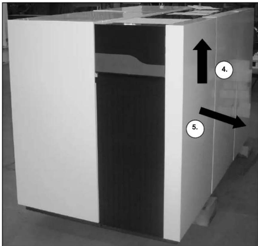
Removing the casing
Boiler transport
Remove the casing before transporting the boiler, in order to avoid damage to the casing parts during transportation. Removing the casing is done as follows:
Boiler installation
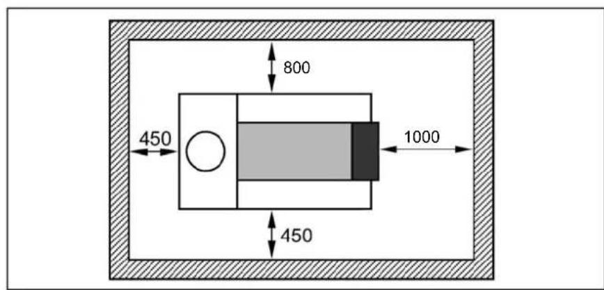
Boiler installation
The boiler should be positioned in a frost-proof boiler room. If the boiler room is on the roof, the boiler itself may never be the highest point of the installation.
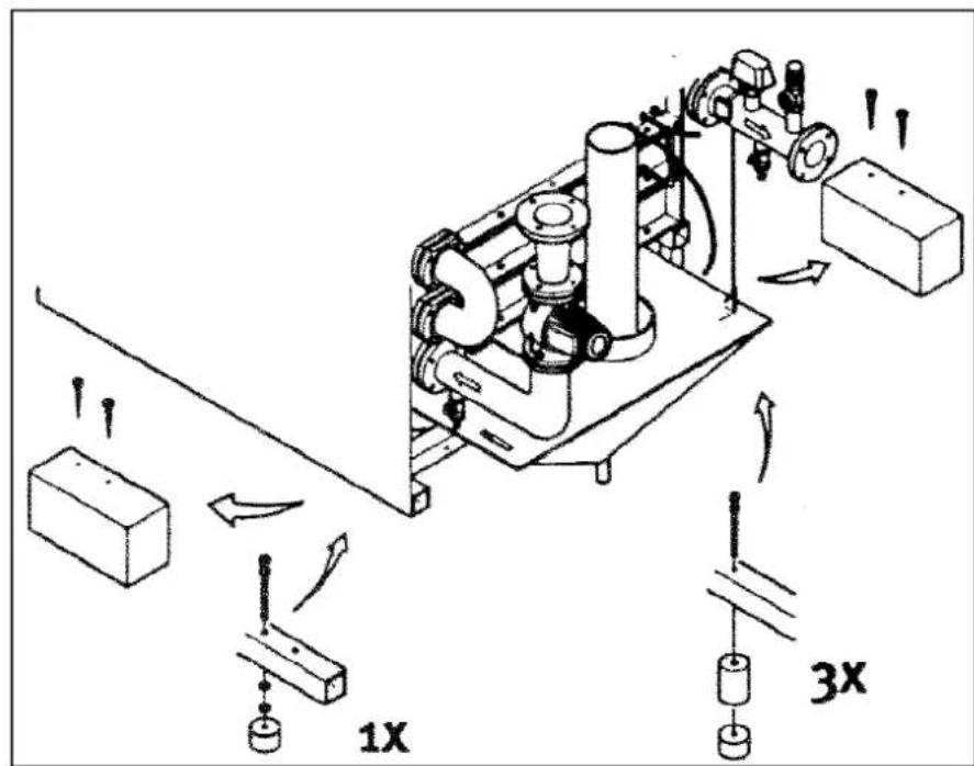
When positioning the boiler, please note the recommended minimum clearance in the picture. When the boiler is positioned with less free space, maintenance activities will be more difficult.
Once the boiler is in the correct position, the wooden blocks (1) should be removed and the adjustable feet (2) (with vibration absorption dampers) should be adjusted to the right height. Water and gas connections should be done after mounting the feet, as they effect the exact height of all connections.
The R3407-R3410 are not supplied on wooden blocks, but on wheels. After positioning the boiler, the adjustable feet have to be set to the correct height. The wheels have to be removed. The connections to the boiler have to be made after the feet have been adjusted, as the adjustment will effect the exact height of all connections.
Connecting the boiler
Connecting the boiler
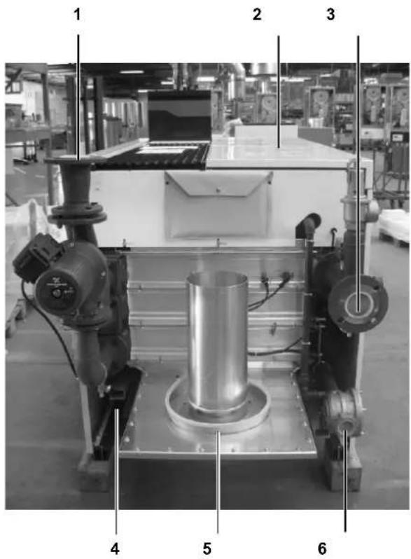
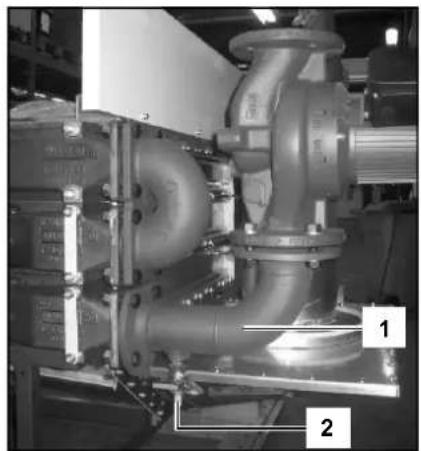
This chapter will explain how to make all connections to the boiler with regard to:
- Hydraulic connections (1, 3)
- Condensate drain connection (7)
Gas connection (6) - Flue gas connection (5)
Air intake connection (only when using roomsealed, order separately) (2) - Electrical connection (4)
The boiler should always be connected in such a way, that the system applies to all relevant standards and regulations (European, national and local). It's the responsibility of the installer to ensure that all standards and regulations are respected.
Hydraulic connections
The boiler should always be connected in such a way, that water flow through the boiler can be ensured at all times. Connect the flow (3) and return (1) connection of the system tension free to the boiler connections. If the boiler is used in a system with two return circuits (only R3600 series), the common return becomes the low temperature return, the 2nd return connection is the high temperature return (remove cap/ flange before connecting).
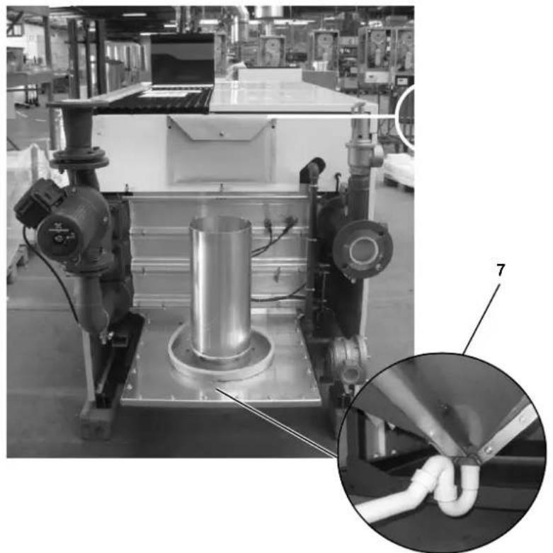
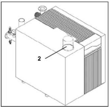
Condensate connection (7)
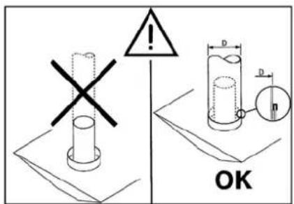
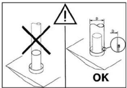
After filling with water, the syphon (included in delivery) should be installed to the connection at the bottom of the condensate receptacle. The connection to the draining system should always be done with an open connection, in order to avoid a flooding of the boiler in case of a blocked drain.
Connecting the boiler
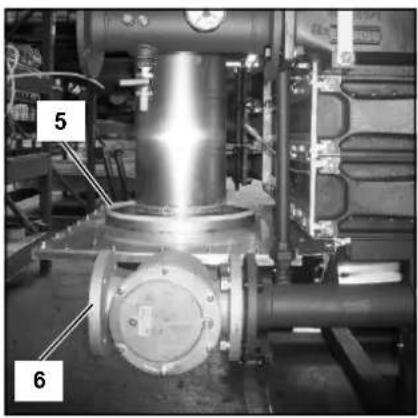
Gas connection (6)
The gas connection must be made by an authorized installer in accordance with the applicable national and local standards and regulations.
Connect the gas line from the system tension free to the gas connection (6) of the boiler. A gas cock should be mounted directly behind the boiler.
A gas filter can be mounted directly on the gas connection of the boiler.
Flue gas connection (5)
Regulations for the construction of flue gas systems are very different for each country. It should be ensured that all national regulations with regard to flue gas systems are respected.
Connect the flue gas system to the flue gas connection (5) of the boiler, use fluegas systems with seamless connections only. It's not necessary to make a separate condensate drain for the flue gas system, as the condensate will be drained via the syphon of the boiler. Please note the following issues:
- It's recommended to use stainless steel systems
- The diameter of the flue gas system must be chosen by calculation according to the national regulations
- Construct the flue gas system as short as possible (for maximum length see planner documentation)
- Construct horizontal ways with a minimum angle of 3^
Air intake connection (3)
When using the boiler roomsealed. The air intake can be connected if the boiler was ordered as roomsealed. The diameter should be calculated according to the national regulations, together with the flue gas system. The total resistance of both systems should never overcome the maximum permissible resistance of the fan inside the boiler (see also chapter: Technical data).
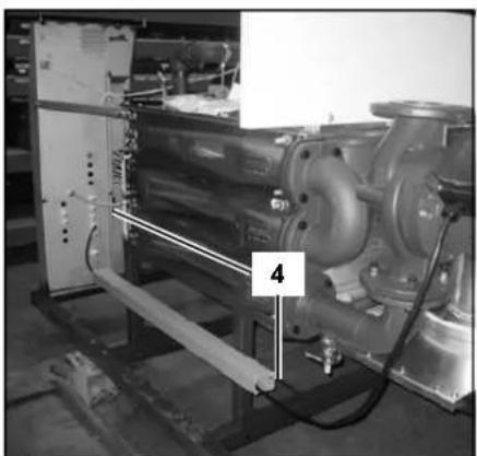
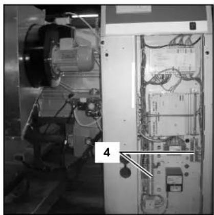
Electrical connection (4)
The electrical connection must be made by an authorized installer in accordance with the applicable national and local standards and regulations.
For the power supply it's necessary to use a mains isolator switch with a contact opening of at least 3mm within the boiler room. This switch can be used to switch off the power supply for maintenance purposes.
Cables can be inserted through the cable trays and glands at the back of the electrical panel at the front of the boiler.
Connect all wires to the terminals according to the wiring diagram of the boiler (enclosed in map attached to back panel of the boiler).
Commissioning
Water and hydraulic system
Commissioning of the boiler should be carried out by authorized personnel only. Failure to respect this condition makes the guarantee void. A protocol of the commissioning should be filled out (see end of this chapter for example of commissioning protocol).
This chapter explains the commissioning of the boiler with the standard boiler controller. When an additional system controller is installed, please refer to its manual for commissioning the controller.
| Boiler output [kW] | Max. sum of alkaline earths \( \left\lbrack {\mathrm{{mol}}/{\mathrm{m}}^{3}}\right\rbrack \) | Max. total hardness \( \left\lbrack {{\mathrm{d}}^{0}\mathrm{H}}\right\rbrack \) |
| 600 - 2000 1.5 8.4 |
Water quality
The system should be filled with water with a PH value between 8,0 and 9,5. The chloride value of the water should not exceed 50~mg / l . Entry of oxygen by diffusion should be prevented at all times. Damage to the heat exchanger because of oxygen diffusion will not be taken under warranty.
In installations with higher water volumes, it's necessary to respect the maximum filling and additional volumes with corresponding hardness values as stated in the german VDI2035 standard. In the table you can find the nominal values for filling and additional water for the R3400/R3500/R3600 according to the VDI2035.
| Concentrate Ca(HCO3)2 | Capacity of installation Q (kW) | |||||||
| 600 | 800 | 1000 | 1200 | 1400 | 1600 | 182000 | ||
| mol/m3 | d°H | Maximum water (re)fill volume V max[m3] | ||||||
| ≤0.5 | ≤2.8 | - | - | - | 75.1 | 87.6 | 100.225.2 | |
| 1.0 | 5.6 | - | - | - | 37.6 | 43.8 | 50.1 | 56.3 |
| 1.5 | 8.4 | 12.0 | 16.7 | 20.9 | 25.0 | 29.2 | 33.4 | 37.6 |
| 2.0 | 11.2 | 9.4 | 12.5 | 15.7 | 18.8 | 21.9 | 25.0 | 28.2 |
| 2.5 | 14.0 | 7.5 | 10.0 | 12.5 | 15.0 | 17.5 | 20.0 | 22.5 |
| ≥3.0 | ≥16.8 | 6.3 | 8.3 | 10.4 | 12.5 | 14.6 | 16.7 | 18.8 |
The table at the left gives an indication of the relation between the water quality and the maximum water filling volume during the lifetime of the boiler. Consult the original text of the VDI2035 for more detailed information.
122.7
Water pressure
Open the valves to the system. Check the water pressure in the system. If the water pressure is too low (see table below), increase the pressure up to at least the minimum required water pressure in the table.
Filling can be done via the fill and drain valve (2) on the return connection (1) of the boiler.
| Minimum operating pressure [bar] | Flow tem- perature \( \left\lbrack {{}^{ \circ }\mathrm{C}}\right\rbrack \) |
| \( > {1.5}\;{90} \) | |
| \( > {1.0}\;{80} \) |
Hydraulic system
Check if the boiler is hydraulically connected to the system in such way, that water flow can be secured at all times during burner operation. The water flow is supervised by the water flow switch in the boiler and a lack of flow will lead to a direct burner stop and lockout of the boiler.
Commissioning
Gas supply
Condensate connection
Flue and air intake connections
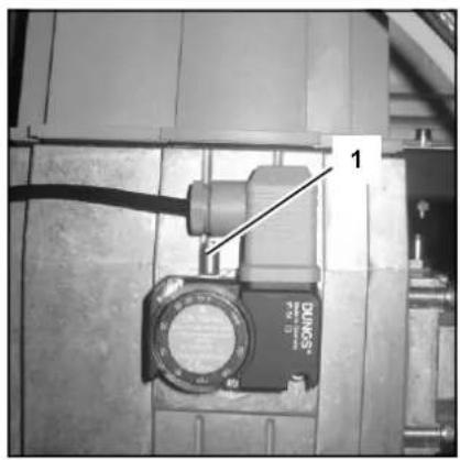
Gas supply
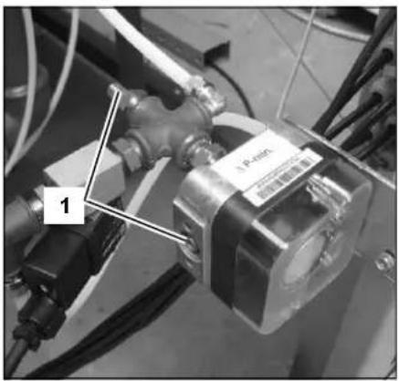
Check the gas supply connection to the boiler for tightness. If any leakage is found, reseal the leakage before starting the boiler!
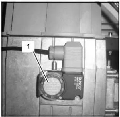
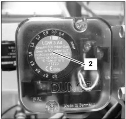
Remove any air between the gas valve and the gas line. This can be done at the test point (1) at the gas pressure switch. Don't forget to close the test point afterwards!
Check the gas type and values with the local gas company, in order to know for which gas type the boiler should be commissioned.
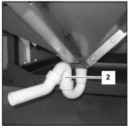
Condensate connection
Remove the syphon (2) from the condensate connection. Fill it with water and place it back in the original position. Make sure the syphon is filled before starting the boiler, in order to prevent flue gases discharging through the condensate connection!
Flue and air intake connections
Check whether the flue and air intake systems are made according to the national and local regulations. Installations which don't comply with the regulations, are not allowed to be commissioned.
Make sure that all connections are free.
The size of flue gas and air intake connections may not be reduced.
Commissioning
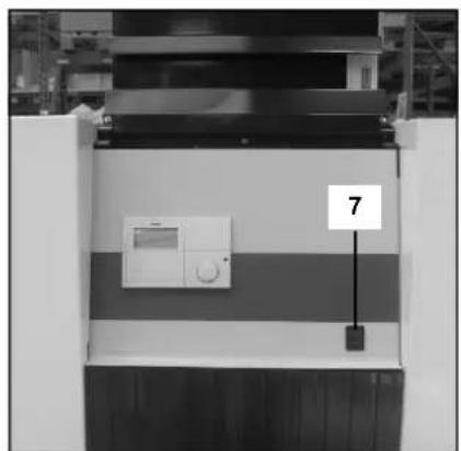
Prepare boiler for first startup
Prepare boiler for first startup
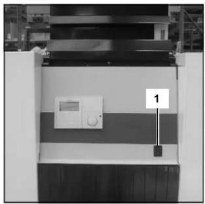
- Open gas connection;
- Switch on mains isolator switch for power supply to the boiler;
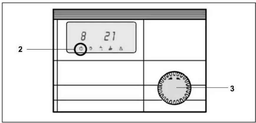
- Switch on boiler with on/off switch (1)
Make sure the boiler remains in standby operation (2) use rotational switch (3);
- Check the pump operation: make sure that the direction of the rotation is correct;
- Remove any air from the pump by removing the end cap of the pump motor housing.
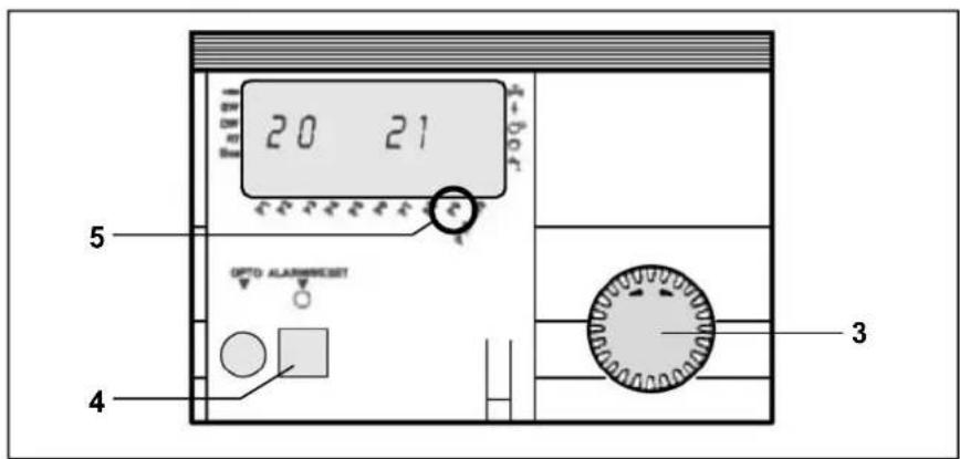
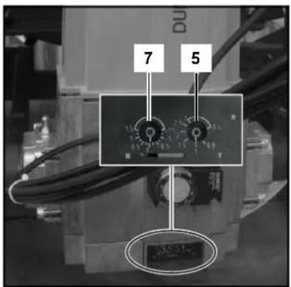
It's recommended to keep the boiler at 50% load for a while after the first startup, as this is the easiest base for starting the combustion analysis. This can be assured as follows:
- Open the lid of the boiler controller;
- Use rotational switch (3) for going to parameter P9 in the menu;
- Change P9 (5) into 50% (push programming button (4), change value with rotational switch (3), push programming button (4) to confirm);
- Close the lid of the boiler controller.
Combustion analysis
Combustion check at full load
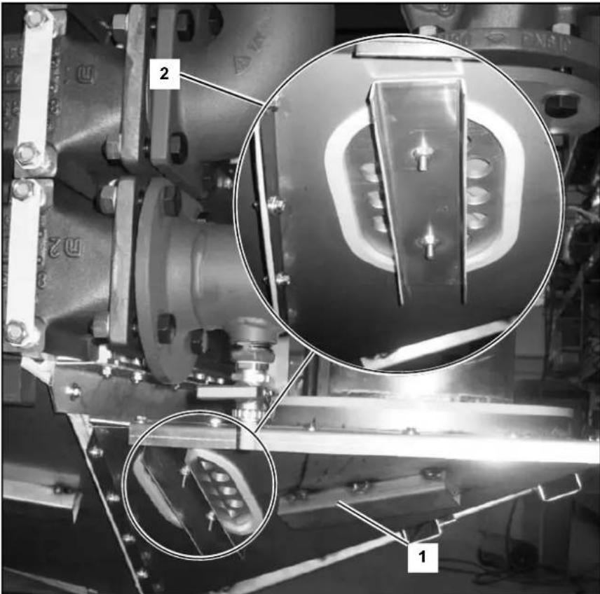
Start the boiler at service mode for full load operation (A II). When you have reduced P9 to 50% (see previous chapter), the boiler will operate at 50% load. Allow the boiler to stabilise the combustion for 3 minutes. Then increase P9 step by step up to 100% . Check the gas pressure on the inlet of the gas valve while increasing the boiler load: the gas pressure should never go below the minimum required value see technical data. Set the minimum gas pressure switch (1) at 50% of the required gas pressure.
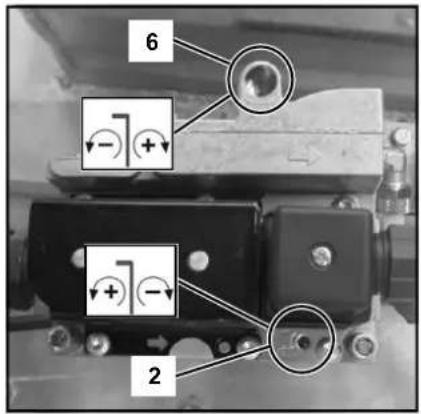
First check the combustion values of the pilot burner using the measuring tube on the back of the boiler (3). If required the values can be corrected with the adjustment screw on the pilot gas valve (2).
Then check the combustion values of the main burner using a measuring point in the flue (4). If required the values can be corrected with the adjustment screw (V) on the main gas valve (5).
| Pilot burner | ||
| Combustion settings for natural gas G20 / G25 | ||
| All boilers | ||
| CO2,max % | 10.0 ± 0.2 | |
| COmax | ppm | < |
| CO2,min % | 10.2 ± 0.2 | |
| COmin | ppm | < |
1000
1000
| Pilot burner | ||
| Combustion settings for LPG G31 | ||
| Parameter change required P19 : 100% ▲ 86% | ||
| All boilers | ||
| CO2, max % | 11.0 ± 0.2 | |
| COmax | ppm | < |
| CO2, min % | 11.2 ± 0.2 | |
| COmin | ppm | < |
1000
1000
Combustion check at minimum load Switch the boiler to service mode for minimum load operation (I). Check the combustion settings the same way as described for full load. The combustion settings for the pilot burner can be adjusted using the adjustment screw on the pilot gas valve (6). The combustion settings for the main burner can be adjusted using the adjustment screw (N) on the main gas valve (7).
Combustion check at 50% load
An additional reference check of combustion values at 50% load is recommended in order to check if the gas valve is set in such way, that the modulating behaviour is normal. The CO_2 value should be in between the settings of full load and minimum load. CO value should be equal to full load and minimum load values.
Make sure parameter P9 is set back to 100 and switch the boiler to automatic operation (O) after the combustion test is finished.
| Main burner | ||
| Combustion settings for natural gas G20 / G25 | ||
| All boilers | ||
| CO2 max % | 10.0 ± 0.2 | |
| COmax | ppm | < |
| CO2, min % | 9.3 ± 0.2 | |
| COmin | ppm | < |
30
30
30
30
| Main burner | ||
| Combustion settings for LPG G31 | ||
| Parameter change required P19 : 100% ▶ 86% | ||
| All boilers | ||
| CO2, max % | 11.0 ± 0.2 | |
| COmax | ppm | < |
| CO2, min % | 11.0 ± 0.2 | |
| COmin | ppm | < |
Commissioning
Air pressure switch
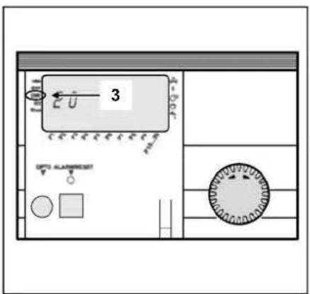
Adjustment Air pressure switch Connect a pressure gauge to the indicated measuring points on the switch (1). Start the boiler at service mode for minimum load operation (A I ) .Measure the pressure differential across the switch, this should be ≈ 0.8 mbar. Turn the dial on the switch (2) counterclockwise until the end. Reduce the setting on parameter P17 step by step until the pressure differential is 0.4 mbar. Slowly turn the dial on the switch clockwise until the boiler goes to lockout. Set P17 back to its original setting!! Reset the lockout. Restart the boiler and check if the switch contact closes at O.4 mbar (indicator at DW in display of the boiler controller (3). If required, repeat the above procedure.
Check water flow
The water flow through the boiler can be checked with two different methods shown below.
T measurement
Check the temperature difference over the boiler ( T flow-return) when the boiler is running on 100% load. The nominal T is 20K and must be at least between 15K and 25K for secure boiler operation. An indication of the actual flow rate can be found with the following calculation (see table below for nominal data):
$$ \mathrm {q} _ {\text {a c t u a l}} = \left(\Delta \mathrm {T} _ {\text {n o m i n a l}} / \Delta \mathrm {T} _ {\text {m e a s u r e d}}\right) ^ {*} \mathrm {q} _ {\text {n o m i n a l}} [ \mathrm {m} ^ {3} / \mathrm {h} ] $$
p measurement
Check the pressure difference over the boiler ( p flow-return) when the boiler pump is running (burner on is not required). The nominal p for each boiler type can be found in the table below, actual p must be within: 0.35^ p_nom≤ P≤ 1.75^ p_nom .An indication of the actual flow rate can be found with the following calculation (see table below for nominal data):
$$ \mathrm {q} _ {\text {a c t u a l}} = \sqrt {\left(\Delta \mathrm {p} _ {\text {m e a s u r e d}} / \Delta \mathrm {p} _ {\text {n o m i a l}}\right) ^ {*} \mathrm {q} _ {\text {n o m i a l}} \left[ \mathrm {m} ^ {3} / \mathrm {h} \right]} $$
| Flow rate R3401 - R3405 at ΔT 20K | ||||||
| R3401 | R3402 | R3403 | R3404 | R3405 | ||
| Nominal flow | [m³/h] | 28.5 | 31.6 | 37.0 | 41.8 | 46.8 |
| Δp at nom. flow | [kPa] | 46 | 53 | 36 | 43 | 50 |
| Flow rate R3406 - R3410 at ΔT 20K | ||||||
| R3406 | R3407 | R3408 | R3409 | R3410 | ||
| Nominal flow | [m³/h] | 51,6 | 56,1 | 64,1 | 72,1 | 80,1 |
| Δp at nom. flow | [kPa] | 58 | 91 | 60 | 130 | 165 |
| Flow rate R3501 - R3505 at ΔT 20K | ||||||
| R3501 | R3502 | R3503 | R3504 | R3505 | ||
| Nominal flow | [m³/h] | 26,4 | 30,8 | 34,9 | 39,0 | 43,0 |
| Δp at nom. flow | [kPa] | 37 | 25 | 30 | 35 | 40 |
| Flow rate R3600 - R3605 at ΔT 20K | |||||||
| R3600 | R3601 | R3602 | R3603 | R3604 | R3605 | ||
| Nominal flow | [m³/h] | 24,7 | 27,6 | 32,2 | 36,5 | 40,8 | 45,0 |
| Δp at nom. flow | [kPa] | 48 | 56 | 38 | 45 | 53 | 60 |
Commissioning
Check functionality of safety devices Gas tightness check Boiler shut down
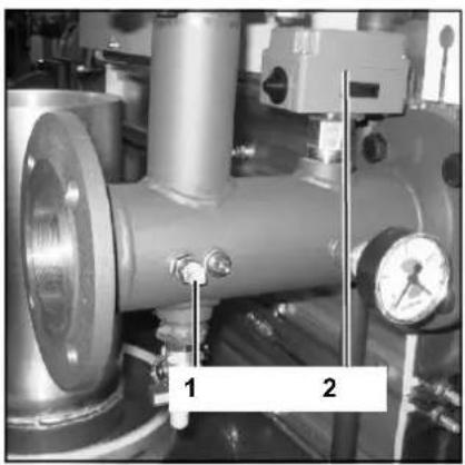
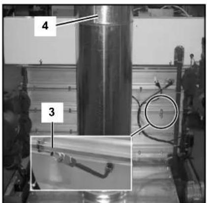
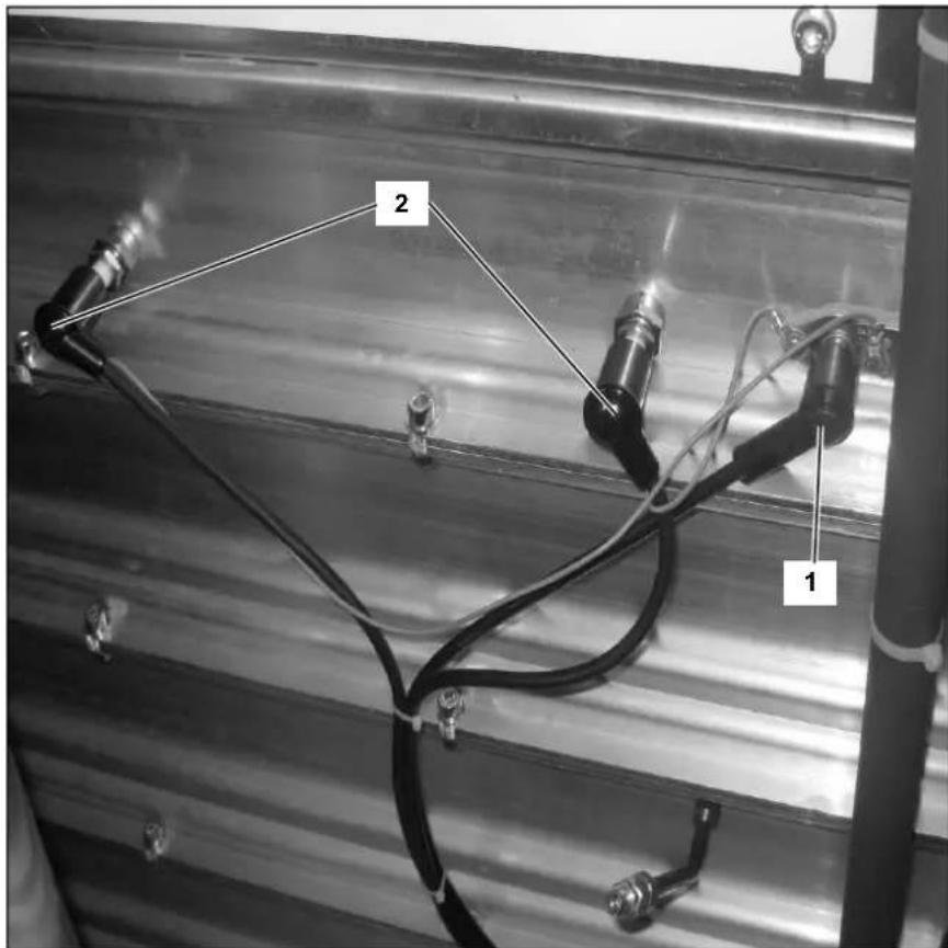
Check functionality of safety devices All safety devices have to be checked on good functioning. Safety devices on a standard boiler are a water flow temperature sensor, water flow switch, minimum gas pressure switch and ionisation electrode. These devices can be checked as described below.
Water flow temperature sensor (1) Disconnect the plug from the sensor while the boiler is switched on. This should result in a lockout no. 12. The lockout should disappear as soon as the plug is placed back in position, the boiler will restart.
Water flow switch (2)
Close (slowly!) the valve in the flow connection to the system while the boiler is running on minimum load. When the valve is almost closed and the water flow is insufficient, the water flow switch will switch off and the boiler will go in lockout 40. Open the valve. A manual reset is necessary.
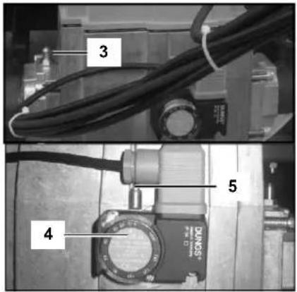
Minimum gas pressure switch (4)
Close the gas cock when the boiler is in standby position (6). Open the test point on the gas valve (3) while measuring the gas pressure on the test point of the gas pressure switch (5). The boiler will go in lockout no. 2 when the switch off setting is achieved. Close both test points and open the gas cock.
Ionisation electrode (6)
Remove electrical connection from the ionisation electrode while the boiler is running, the boiler will go in lockout no.5. The boiler will try to restart. With the electrical connection removed, the restart will result in lockout no.4. When the connection is already mounted, the restart will be successful.
Measuring the ionisation current can be done by mounting a multi-meter (set to A ) in between the ionisation electrode and its electrical connection. The ionisation current should always be above 1.2 A , in normal conditions it will be 6 A and above.
Gas tightness check
Check the gas tightness of all sealed connections with an approved soap or electronic gas analyzer, for example:
Test points
- Bolt connections
- Gaskets of mixing system, etc.
Boiler shut down
When the boiler will not be used for longer periods, shut down the boiler by following procedure:
- Switch the boiler in standby operation (6)
- Switch off the boiler with the on/off switch (7)
- Disable power supply to the boiler by deactivating the mains isolator switch in the boiler room
- Close the gas supply to the boiler.
Commissioning protocol
| Commissioning Protocol R3400/R3500/R3600 | |||
| Project | |||
| Boiler type Project | |||
| Serial number Address | |||
| Year City | |||
| Nominal load (Hi) [kW] Date | |||
| Nominal output (Hi) [kW] Engineer | |||
| System | |||
| Water pressure [bar] Installati- | on: | Roof top | ☐ |
| Water pH [-] Ground floor | ☐ | ||
| Water hardness [d°H] Basement | ☐ | ||
| Water chloride [mg/l] | Other: | ☐ | |
| Water ΔT full load [°C] | Hydrau-Placed heat exo | Low velocity header | ☐ |
| Water Δpboiler [kPa] | hanger | ☐ | |
| Water flow [m3/h] | Bypass boiler | ☐ | |
| Pump setting [-] | Other: | ☐ | |
| Safety devices | |||
| High limit setting [°C] | Water flow sensor checked | ☐ | |
| Temp. limiter setting [°C] | Water flow switch checked | ☐ | |
| Min. gas pressure switch setting [mbar] | |||
| Ignition time burner [sec] | |||
| Combustion analysis | |||
| 100% load | 50% load | Min. load | |
| Gas consumption | [m3/h] | [m3/h] | [m3/h] |
| Gas pressure [mbar] | [mbar] | [mbar] | |
| CO2 pilot burner | [%] | [%] | [%] |
| O2 pilot burner | [%] | [%] | [%] |
| CO pilot burner [ppm] | [ppm] | [ppm] | |
| NOx pilot burner | [ppm] | [ppm] | [ppm] |
| CO2 main burner | [%] | [%] | [%] |
| O2 main burner | [%] | [%] | [%] |
| CO main burner | [ppm] | [ppm] | [ppm] |
| NOx main burner | [ppm] | [ppm] | [ppm] |
| Tatmospheric | [°C] | [°C] | [°C] |
| Tfluegas | [°C] | [°C] | [°C] |
| Twater, flow | [°C] | [°C] | [°C] |
| Twater, return | [°C] | [°C] | [°C] |
| Ionisation current | [μA] | [μA] | [μA] |
| pfan | [mbar] | [mbar] | [mbar] |
| Ptop panel | [mbar] | [mbar] | [mbar] |
| Pcombustion chamber | [mbar] | [mbar] | [mbar] |
| Parameter settings | |||
| P1 Setpoint temperature heating [°C] | P12 Boiler hysteresis [°C] | ||
| P2 Setpoint temperature DHW [°C] | P17 Fan speed min. load [‰] | ||
| P11 Maximum boiler setpoint [°C] | P19 Fan speed 100% load [‰] | ||
| Remarks | |||
Operating instructions
Main menu (operating mode) Parameter menu (information/programming mode) Changing parameter values
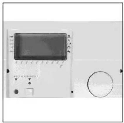
The boiler controller has two menus: the main menu (operating mode) when the lid is closed, and the parameter menu (information/programming mode) when the lid is open. Both menus and possibilities are explained in the next paragraphs.
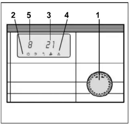
Main menu (operating mode) lid closed
With the lid closed and by using the rotational switch (1) clockwise or anticlockwise, the boilers' operating mode (2) can be set. The available modes are:
念 Standby mode (only frost protection)
Automatic operation mode (heating and DHW)
Summer mode (only DHW, no heating)
I Service mode minimum load
Service mode full load (limited by P9)
Besides the operating mode, the display also shows the actual water flow temperature (3) and, in case of a lockout, a warning triangle (4) combined with a lockout code (5). The explanation of the lockout codes can be found in chapter "Lockouts".
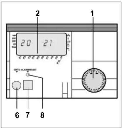
Parameter menu (information/programming mode) lid open
With the lid open and by using the rotational switch (1) clockwise or anticlockwise it's possible to read/change certain values/parameters from the boiler controller. An arrow at the bottom of the display (2) indicates which parameter has been selected. The available values/parameters are:
P1 Actual / setpoint water flow temperature [^ C]
P2 Actual/setpoint DHW temperature [^ C]
P3 Actual temperature/capacity setpoint for boiler [^o C]^*
P4
P5 Actual outside temperature [^ C] (if sensor is connected)
P6 Actual fluegas temperature [^ C]
P7
P8 Actual low velocity header temperature [^ C] (if sensor is connected)
P9 Actual / Limit boiler output [%]
P10 Password for advanced settings
- P3 shows the actual temperature setpoint of the boiler, either coming from P1/P2 or from an additional (weather compensated) controller or building management system (2-10V). When the boiler capacity is controlled via a cascade manager or building management system (2-10V), P3 shows the actual capacity setpoint of the boiler.
Behind the lid you find an optical I/O connection (6), a reset/programming button (7) and an alarm/programming LED (8). Besides the parameter values/ settings, the display also shows additional information with regard to input and output indications to and from the boiler:
Output indications
Power to main gas valve
Power to ignition transformer
Fan control signal
Power to primary boiler pump
Power to DHW pump/diverter valve
Input indications
Flame ionisation detected
SW Water flow switch active
DW Air pressure switch active
RT Boiler enabled**
Bus Bus communication active
**The boiler enable signal is equipped with a jumper in the standard delivery and therefore the boiler will normally be enabled. If a building management system is connected to provide the enable signal to the boiler (jumper should be removed), check the building management system if the boiler remains disabled.
Changing parameter values
For changing any parameters, in the example parameter P2 (DHW setpoint), the following procedure should be carried through:
- Open the lid (the arrow at the bottom of the display indicates parameter P1)
-
Turn the rotational switch clockwise until the arrow indicates parameter P2
-
Press the reset/programming button to select (the LED lights up)
- Turn the rotational switch until the desired DHW setpoint value has been reached
- Press the reset/programming button to confirm (the LED goes out)
- Close the lid.
The new value is now activated. All parameters can be changed by following the same procedure as described above.
Maintenance
Checklist Replacing the electrodes
Maintenance of the boiler should be carried out by authorized personnel only.
In order to ensure continued good and safe operation of the boiler, it should be inspected at least once per year. A maintenance protocol should be filled out (see end of this chapter for example of maintenance protocol).
Checklist
The following activities must be carried out, see following paragraphs for an extensive description of the main activities:
- Replace the ignition and ionisation electrodes;
- Clean the condensate receptacle;
- Clean and refill the syphon;
- Check the water pressure of the system;
- Check the water quality of the system water as well as supply water;
- Check the water flow rate through the boiler;
- Check/correct the combustion values at full and minimum load with a combustion analyzer;
- Check the gas pressure to the boiler;
- Check the tightness of all sealed connections and test points;
- Check the functionality of all safety devices;
- Fill out a maintenance protocol.
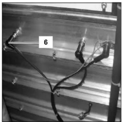
Replacing the electrodes
The electrodes are positioned on the right hand side of the boiler. Replace the ignition electrode (1) and ionisation electrodes (2) as shown on the picture.
Maintenance
Cleaning the condensate receptacle Cleaning and refilling the syphon
Cleaning the condensate receptacle
- Remove the inspection hatch (2) to access the inside of the condensate receptacle;
Clean the receptacle; - Mount the inspection hatch.
Water pressure and quality
Check if the water pressure and quality meet the requirements. Consult the chapter "commissioning: water and hydraulic system" for more detailed information.
Water flow rate
Check if the water flow rate through the boiler is within the limits. Consult the chapter "commissioning: check water flow" for more detailed information.
Combustion analysis
Check the combustion at full load and minumum load, correct the settings if necessary. An additional reference check at 50% load is recommended. Consult the chapter "commissioning: combustion analysis" for more detailed information.
Gas pressure
Check the dynamic pressure of the gas supply to the boiler, when the boiler is running at full load. In case of a boiler cascade, all boilers should be running at full load. See technical data for required values.
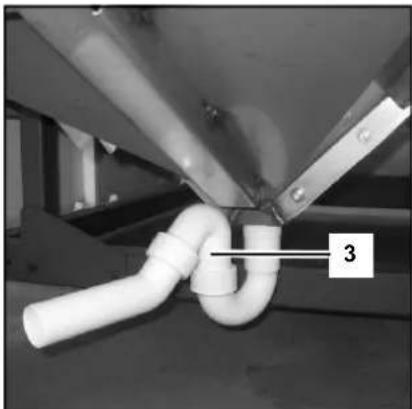
Cleaning and refilling the syphon
- Remove the syphon (3) from the condensate connection;
- Clean and fill it with fresh water;
- Mount the syphon back in the original position.
Maintenance Protocol
| Maintenance Protocol R3400/R3500/R3600 | |||
| Project | |||
| Boiler type Project | |||
| Serial number Address | |||
| Year City | |||
| Nominal load (Hi) [kW] Date | |||
| Nominal output (Hi) [kW] Engineer | |||
| System | |||
| Water pressure [bar] | |||
| Water pH [-] | |||
| Water hardness [d°H] | |||
| Water chloride [mg/l] | |||
| Water ΔT full load [°C] | |||
| Water Δρboller [kPa] | |||
| Water flow [m3/h] | |||
| Pump setting [-] | |||
| Safety devices | |||
| High limit setting [°C] | Water flow sensor checked ☐ | ||
| Temp. limiter setting [°C] | Water flow switch checked ☐ | ||
| Min. gas pressure switch setting [mbar] | |||
| Ignition time burner [sec] | |||
| Combustion analysis | |||
| 100% load | 50% load | Min. load | |
| Gas consumption | [m3/h] | [m3/h] | [m3/h] |
| Gas pressure [mbar] | [mbar] | [mbar] | |
| CO2 Pilot burner | [%] | [%] | [%] |
| O2 Pilot burner | [%] | [%] | [%] |
| CO Pilot burner | [ppm] | [ppm] | [ppm] |
| NOx Pilot burner | [ppm] | [ppm] | [ppm] |
| CO2 Main burner | [%] | [%] | [%] |
| O2 Main burner | [%] | [%] | [%] |
| CO Main burner | [ppm] | [ppm] | [ppm] |
| NOx Main burner | [ppm] | [ppm] | [ppm] |
| Tatmospheric | [°C] | [°C] | [°C] |
| Tfluegas | [°C] | [°C] | [°C] |
| Twater, flow | [°C] | [°C] | [°C] |
| Twater, return | [°C] | [°C] | [°C] |
| Ionisation current | [μA] | [μA] | [μA] |
| pfan | [mbar] | [mbar] | [mbar] |
| topanel | [mbar] | [mbar] | [mbar] |
| combustion chamber | [mbar] | [mbar] | [mbar] |
| Parameter settings | |||
| P1 Setpoint temperature heating [°C] | P12 Boiler hysteresis [°C] | ||
| P2 Setpoint temperature DHW [°C] | P17 Fan speed min. load [%] | ||
| P11 Maximum boiler setpoint [°C] | P19 Fan speed 100% load [%] | ||
| Remarks | |||
In case of a lockout, a warning triangle () and a flashing error code appears on the display. The cause of a fault should first be determined and eliminated before the boiler is being reset. In case the lockout appears more than twice within 6 minutes or maintains for longer than 6 minutes, the error code is added with a n^3 . The table below shows all possible lockouts and an indication of possible cause.
| No. | Error type | Explanation | Possible solution |
| 1 | Lockout Water flow temperature has exceeded the high limit temperature setting (100°C). | Check if boiler is in automatic mode (K), Check if water flow through the boiler is sufficient, check if (P11+P12) < High limit setting (V9). | |
| 2 | Interlock Gas pressure has dropped below minimum value of minimum gas pressure switch or additional safety device connected to the interlock input has been interrupted (during startup). | Check gas supply pressure / check function of additional safety device on interlock input. | |
| 3 | Interlock Gas pressure has dropped below minimum value of minimum gas pressure switch or additional safety device connected to the interlock input has been interrupted (during operation). | Check gas supply pressure / check function of additional safety device on interlock input. | |
| 4 | Lockout No flame ionisation signal detected during burner start. | Check phase/neutral of power supply (phase sensitivity!), check gas supply, check ignition spark, increase gas valve setting min. load (alan key screw). | |
| 5 | Lockout Flame ionisation signal lost during operation. Check gas | gas supply pressure during operation, check gas valve setting via combustion analysis. | |
| 6 | Interlock Water flow temperature has exceeded the temperature limiter setting (97°C). | Check if boiler is in automatic mode (Φ), check if water flow through the boiler is sufficient, check if (P11+P12) < Temp. limiter setting (V10). | |
| 7 | Lockout External safety device connected to the lockout input has been interrupted. | Check the external safety devices (water pressure switches, safety thermostat, etc.) | |
| 11 | Lockout Flame ionisation signal detected before burner start. | Check ionisation electrode, measure ionisation current when boiler is off, check wiring between ionisation electrode and boiler controller. | |
| 12 | Interlock Water flow temperature sensor is defective. | Check resistance of sensor (see chapter "sensor values"), check wiring between water flow temperature sensor and boiler controller. | |
| 14 | Interlock DHW temperature sensor (optional) is defective. | Check resistance of sensor (see chapter "sensor values"), check wiring between DHW temperature sensor and boiler controller. | |
| 15 | Interlock Outside temperature sensor (optional) is defective. | Check resistance of sensor (see chapter "sensor values"), check wiring between outside temperature sensor and boiler controller. | |
| 18 | Interlock Header temperature sensor (optional) is defective. | Check resistance of sensor (see chapter "sensor values"), check wiring between header temperature sensor and boiler controller. | |
| 20 | Lockout Error gas valve V1, flame ionisation signal detected longer than 5 seconds after burner stop. | Check closing position of valve V1 within gas combi valve, replace gas valve. | |
| 21 | Lockout Error gas valve V2, flame ionisation signal detected longer than 5 seconds after burner stop. | Check closing position of valve V2 within gas combi valve, replace gas valve. | |
| 22 | Lockout | APS contact does not close during prepurge. | Check setting APS, check if fan is running. |
| 23 | Lockout APS contact remains closed when fan is off. Check setting APS | ||
| 27 | Lockout APS contact opens during operation. Check setting APS | ||
| 30 | Lockout CRC error in control system parameters (P11-P40). | Check parameter settings of P11-P40, change value of one parameter within P11-P40 (lockout disappears), change all parameters back to original settings. | |
| 31 | Lockout CRC error in boiler safety parameters (V1-V16). | Check parameter settings of V1-V16, change value of one parameter within V1-V16 (lockout disappears), change all parameters back to original settings. | |
| 32 | Interlock Power supply voltage to boiler controller is too low. | Check fuse of boiler controller, check power supply to boiler controller. | |
| 40 | Lockout Water flow switch has been interrupted when pump being enabled. | Check pump operation, check water flow through the boiler, check functionality of water flow switch. | |
| x.y. | Lockout (all) lockout codes which are not listed above) Internal lockout of boiler controller. | Press reset. Change boiler controller when lockout can not be reset or occurs more frequently. | |
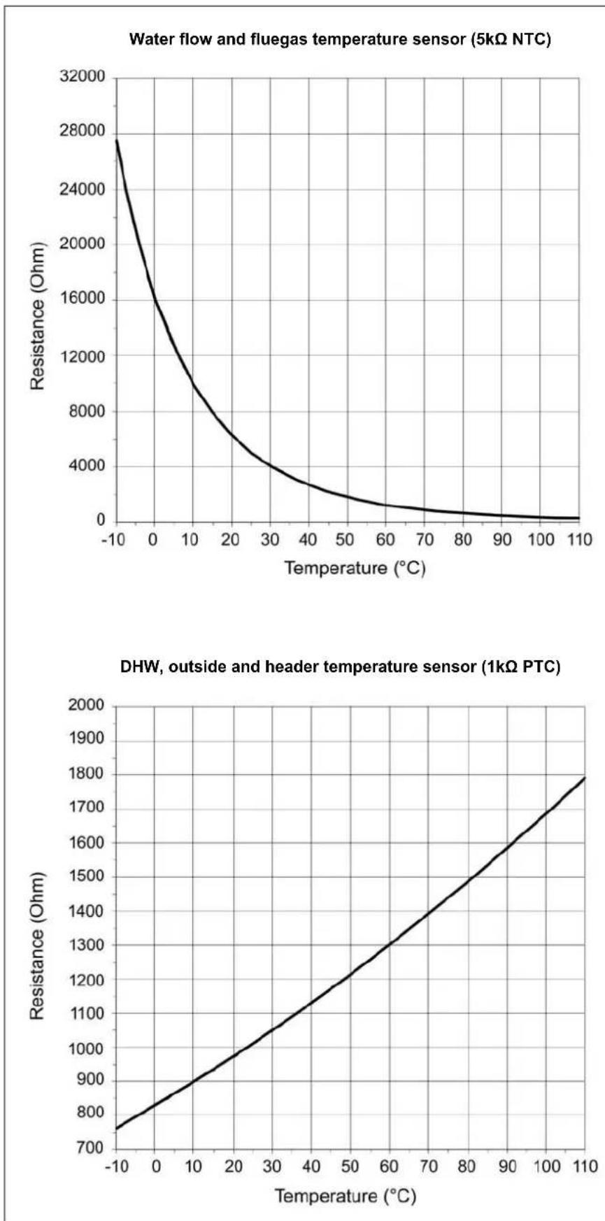
The diagrams show the sensor values for all boiler sensors and optional sensors available in accessory kits. The diagrams contain average values, as all sensors are liable to tolerances.
When measuring the resistance values, the boiler should always be switched off. Measure close to the sensor, in order to avoid value deviations.
Declaration of Conformity
Rendamax BV, Hamstraat 76, 6465 AG Kerkrade (NL), declares that the products
R3400/3500/3600
are in conformity with the following standards:
EN 656
EN 15417
EN 13836
EN 55014-1/-2
EN 61000-3-2 /-3
EN 60 335-1/-2
and in accordance with the guidelines of directives:
92/42/EEC (boiler efficiency directive)
90 / 396 / EEC (gas appliance directive)
73/23/EEC (low voltage directive)
89/336/EEC (EMC directive)
These products are designated with CE nr.:
CE-0063AR3514
Kerkrade, 10-06-2013

A.J.G. Schuiling
Plant Manager
Inhalt
Abmessungen R3600 - R3605 Split system


| Abmessung | R3600 | R3601 | R3602 | R3603 | R3604 | R3605 | |
| L | mm 19 | 58 20 | 70 24 | 43 24 | 43 24 | 43 24 | 43 1166 88 1166 |
| L2 | mm 700 | 590 | 1166 | 1166 | |||
| L3 | mm | 108 | 198 | 88 | 88 | 88 | |
| H mm | 1355 | 1405 | 1405 | 1405 | 1405 | 1405 | |
| B mm | 1230 | 1330 | 1130 | 1130 | 1330 | 1330 | |
| B1 mm | 1110 | 1210 | 1003 | 1053 | 1203 | 1253 | |
| B2 mm | 615 | 665 | 565 | 565 | 665 | 665 | |
| B3 mm | 120 | 120 | 127 | 77 | 127 | ||
| B4 mm | 1046 | 1146 | 946 | 946 | 1146 | ||
| B5 mm | 100 | 65 | 115 | 65 | 115 | 65 | |
| D mm | 300 | 300 | 350 | 350 | 400 | 400 | |
| D1 mm | 250 | 250 | 300 | 300 | 355 | 355 | |
| W1 DN | DN65 PN16 | DN65 PN16 | DN80 PN16 | DN80 PN16 | DN80 PN16 | DN80 PN16 | |
| W2 DN | DN65 PN16 | DN65 PN16 | DN80 PN16 | DN80 PN16 | DN80 PN16 | DN80 PN16 | |
| W3 DN | DN65 PN16 | DN65 PN16 | DN80 PN16 | DN80 PN16 | DN80 PN16 | DN80 PN16 | |
| G R | R 2" | R 2" | R 2" | R 2" | DN65 PN16 | DN65 PN16 | |
Lieferumfang
Standardausführung
Zubehör
Standard Ausführung
(boiler efficiency directive)
-90/396/EEC
(gas appliance directive)
-73/23/EEC
(low voltage directive)
-89/336/EEC
(EMC directive)
-EN656
Gas-fired central heating boilers - Type B boilers of nominal heat input exceeding 70 kW but not exceeding 300 kW
-EN15417
Gas-fired central heating boilers - Specific requirements for condensing boilers with a nominal heat input greater than 70kW but not exceeding 1000 kW
-EN13836
Gas fired central heating boilers - Type B boilers of nominal heat input exceeding 300 kW, but not exceeding 1000 kW
- EN 15502-1
Gas-fired central heating boilers - Part 1: General requirements and tests
-EN55014-1
Electromagnetic compatibility - Requirements for household appliances, electric tools and similar apparatus - Part 1: Emission
- EN 61000-3-2
Electromagnetic compatibility (EMC) - Part 3-2: Limits - Limits for harmonic current emissions (equipment input current 16 A per phase)
EN61000-3-3
Electromagnetic compatibility (EMC) - Part 3-3: Limitation of voltage changes, voltage fluctuations and flicker in public low-voltage supply systems, for equipment with rated current 16 A per phase and not subject to conditional connection
- EN 60335-1
Household and similar electrical appliances - Safety - Part 1: General requirements
-EN50165
Household and similar electrical appliances - Safety - Part 2-102: Particular requirements for gas, oil and solid-fuel burning appliances having electrical connections
Aanyullende nationale normen:
Duitsland:
- RAL - UZ 61 / DIN 4702-8
Zwitserland:
Afmetingen R3600 - R3605 Split system

| Afmeting | R3600 | R3601 | R3602 | R3603 | R3604 | R3605 | |
| L | mm | 1958 | 2070 | 2443 | 2443 | 2443 | 2443 |
| L2 | mm | 700 | 590 | 1166 | 1166 | 1166 | |
| L3 | mm | 108 | 198 | 88 | 88 | 88 | |
| H | mm | 1355 | 1405 | 1405 | 1405 | 1405 | 1405 |
| B | mm | 1230 | 1330 | 1130 | 1130 | 1330 | 1330 |
| B1 | 1110 | 1210 | 1003 | 1053 | 1203 | 1253 | |
| B2 | mm | 615 | 665 | 565 | 565 | 665 | 665 |
| B3 | mm | 120 | 120 | 127 | 77 | 127 | 77 |
| B4 | mm | 1046 | 1146 | 946 | 946 | 1146 | 1146 |
| B5 | mm | 100 | 65 | 115 | 65 | 115 | 65 |
| D | mm | 300 | 300 | 350 | 350 | 400 | 400 |
| D1 | mm | 250 | 250 | 300 | 300 | 355 | 355 |
| W1 | DN | DN65 PN16 | DN65 PN16 | DN80 PN16 | DN80 PN16 | DN80 PN16 | DN80 PN16 |
| W2 | DN | DN65 PN16 | DN65 PN16 | DN80 PN16 | DN80 PN16 | DN80 PN16 | DN80 PN16 |
| W3 | DN | DN65 PN16 | DN65 PN16 | DN80 PN16 | DN80 PN16 | DN80 PN16 | DN80 PN16 |
| G | R | R 2" | R 2" | R 2" | R 2" | DN65 PN16 | DN65 PN16 |
Standaard toestel
Accessoires
Standaard toestel
92/42/EEC (boiler efficiency directive)
90 / 396 / EEC (gas appliance directive)
73/23/EEC (low voltage directive)
89/336/EEC (EMC directive)
17 Raccordement cheminee
18 Récipient de condensation
22 Raccordement condensation
23 Vanne gaz principale
24 Ventilateur
25 Boite électrique
Dimensions R3600 - R3605 Standard

| Dimensions | R360601 | R3602 | R3603 | R3604 | R3605 | |
| L mm | 1958 | 2265 | 2653 | 2653 | 2658 | 2658 |
| L1 | mr595 | 595 | 610 | 610 | 615 | 615 |
| L2 mm | 700 | 590 | 1166 | 1166 | 1166 | 1166 |
| L3 mm | 108 | 198 | 88 | 88 | 88 | 88 |
| H mm | 1355 | 1405 | 1405 | 1405 | 1405 | 1405 |
| H1 | mm 970 | 1175 | 1450 | 1450 | 1205 | 1427 |
| B mm | 1230 | 1330 | 1130 | 1130 | 1330 | 1330 |
| B1 mm | 1110 | 1210 | 1003 | 1053 | 1203 | 1253 |
| B2 mm | 615 | 665 | 565 | 565 | 665 | 665 |
| B3 mm | 120 | 120 | 127 | 77 | 127 | 77 |
| B4 mm | 1046 | 1146 | 946 | 946 | 1146 | 1146 |
| B5 mm | 100 | 65 | 115 | 65 | 115 | 65 |
| D mm | mm300 | 300 | 350 | 350 | 400 | 400 |
| D1 mm | 250 | 250 | 300 | 300 | 355 | 355 |
| W1 DN | DN65 PN16 | DN65 PN16 | DN80 PN16 | DN80 PN16 | DN80 PN16 | DN80 PN16 |
| W2 DN | DN65 PN16 | DN65 PN16 | DN80 PN16 | DN80 PN16 | DN80 PN16 | DN80 PN16 |
| G R | R 2" | R 2" | R 2" | R 2" | DN65 PN16 | DN65 PN16 |
Caracteristiques techniques R3600 - R3605 Split System
Dimensions R3600 - R3605 Split System


| Dimensions | R3600 | R3601 | R3602 | R3603 | R3604 | R3605 | |
| L | mm | 1958 | 2070 | 2443 | 2443 | 2443 | 2443 |
| L2 | mm | 700 | 590 | 1166 | 1166 | 1166 | |
| L3 | mm | 108 | 198 | 88 | 88 | 88 | |
| H | mm | 1355 | 1405 | 1405 | 1405 | 1405 | 1405 |
| B | mm | 1230 | 1330 | 1130 | 1130 | 1330 | 1330 |
| B1 | 1110 | 1210 | 1003 | 1053 | 1203 | 1253 | |
| B2 | 615 | 665 | 565 | 565 | 665 | 665 | |
| B3 | 120 | 120 | 127 | 77 | 127 | ||
| B4 | mm | 1046 | 1146 | 946 | 946 | 1146 | 1146 |
| B5 | mm | 100 | 65 | 115 | 65 | 115 | 65 |
| D | mm | 300 | 300 | 350 | 350 | 400 | 400 |
| D1 | mm | 250 | 250 | 300 | 300 | 355 | 355 |
| W1 | DN | DN65 PN16 | DN65 PN16 | DN80 PN16 | DN80 PN16 | DN80 PN16 | DN80 PN16 |
| W2 | DN | DN65 PN16 | DN65 PN16 | DN80 PN16 | DN80 PN16 | DN80 PN16 | DN80 PN16 |
| W3 | DN | DN65 PN16 | DN65 PN16 | DN80 PN16 | DN80 PN16 | DN80 PN16 | DN80 PN16 |
| G | R | R 2" | R 2" | R 2" | R 2" | DN65 PN16 | DN65 PN16 |
Raccordements hydrauliques
Pression hydraulique
89/336/EEC (directive EMC)
Dimensioni R3600 - R3605 systemd split
| Dimensioni | R3600 | R3601 | R3602 | R3603 | R3604 | R3605 |
| L | mm 1958 | 2070 | 2443 | 2443 | 2443 | 2443 |
| L2 | mm 700 | 590 | 1166 | 1166 | ||
| L3 | mm 108 | 198 | 88 | 88 | 88 | |
| H | mm 1355 | 1405 | 1405 | 1405 | 1405 | 1405 |
| B | mm 1230 | 1330 | 1130 | 1130 | 1330 | 1330 |
| B1 | mm 1110 | 1210 | 1003 | 1003 | 1203 | 1203 |
| B2 | mm 615 | 665 | 565 | 565 | 665 | 665 |
| B3 | mm 120 | 120 | 127 | 77 | 127 | 77 |
| B4 | mm 1046 | 1146 | 946 | 946 | 1146 | 1146 |
| B5 | mm 100 | 65 | 115 | 65 | 115 | 65 |
| D | mm 300 | 300 | 350 | 350 | 400 | 400 |
| D1 | mm 250 | 250 | 300 | 300 | 355 | 355 |
| W1 | DN DN65 PN16 | DN65 PN16 | DN80 PN16 | DN80 PN16 | DN80 PN16 | DN80 PN16 |
| W2 | DN DN65 PN16 | DN65 PN16 | DN80 PN16 | DN80 PN16 | DN80 PN16 | DN80 PN16 |
| W3 | DN DN65 PN16 | DN65 PN16 | DN80 PN16 | DN80 PN16 | DN80 PN16 | DN80 PN16 |
| G | R R2" | R 2" | R 2" | R 2" | DN65 PN16 | DN65 PN16 |