METRIX MX 1 - Multimeter

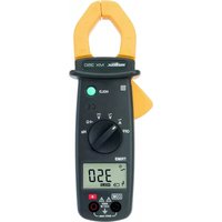
MX 1 - Multimeter METRIX - Free user manual and instructions

Find the device manual for free MX 1 METRIX in PDF.

📄 54 pages English EN 💬 AI Question
Notice METRIX MX 1 - page 14
View the manual : Français FR Deutsch DE English EN Español ES Italiano IT

User questions about MX 1 METRIX

0 question about this device. Answer the ones you know or ask your own.

Ask a new question about this device

L'email reste privé : il sert seulement à vous prévenir si quelqu'un répond à votre question.

No questions yet. Be the first to ask one.

Download the instructions for your Multimeter in PDF format for free! Find your manual MX 1 - METRIX and take your electronic device back in hand. On this page are published all the documents necessary for the use of your device. MX 1 by METRIX.

USER MANUAL MX 1 METRIX

Thank you for purchasing this MX1 multimeter. To obtain the best service from your unit: - Read these operating instructions carefully, - Comply with the precautions for use. Symbols used

CAUTION! Please consult the operating instructions before using the device. In these operating instructions, failure to follow or carry out instructions preceded by this symbol may result in personal injury or damage to the device and the installations. The rubbish bin with a line through it means that in the European Union, the product must undergo selective disposal for the recycling of electric and electronic material, in compliance with Directive WEEE 2002/966/EC. Equipment protected throughout by double or reinforced insulation. Precautions for use

  • Never use on a voltage network over 600 V with respect to the earth connection. This voltage surge category III multimeter complies with stringent reliability and availability requirements, corresponding to fixed industrial and domestic installations (see IEC 664-1).
  • Do not use on alternative and continuous voltages > 600 V.
  • Indoor use in environments with a maximum pollution level of 2 (cf. IEC 664-1) temperature of -10°C to +50°C and relative humidity below 90 %.
  • Respect the value and type of the fuses to avoid damaging the instrument and cancelling the warranty.
  • Use accessories corresponding to safety standards (EN 61010 - 031) with 600 V minimum voltage and surge category III.
  • Before any measurement, ensure correct positioning of the leads on the multimeter and of the switch. When the value range of a measurement is not known, place the switch at the highest calibre, then gradually reduce it until the appropriate calibre is achieved: the reading should preferably be in the upper 2/3 of the range.
  • Never measure resistances on a live circuit.
  • During current intensity measurements (without a clip-on ammeter), stop circuit power supply before connecting or disconnecting the multimeter or changing calibre.
  • The leads must be disconnected to open the lower half of the MX1 casing.
  • Never connect to the circuit to be measured if the casing is not properly closed.English Multimeter MX1 15 Description of instrument Description

(See § Appendix, p. 53). The MX1 multimeter is for everyday use by electricity professionals. It offers the following functions: - Voltmeter voltage measurement (V and ) - Ammeter current intensity measurement (A and ) - Ohmmeter resistance measurement (Ω) with manual calibration. - Audible continuity test

  • COM common, terminal receiving the black lead
  • V Ω for voltage and resistance.
  • 10 A for 10 A calibres ( DC/AC
  • 2 black, with anti-parallaxe mirror, for the VAC, VDC and ADC (a) and (b)
  • 1 green for the Ω measurements (c)
  • 2 red for the AAC measurements (d) and (e)
  • 1 red for the 5 VAC (f)
  • 1 black for the dB measurements (g)

1.6 A and 10 A for intensity or voltage measurements, change the fuse(s)

if the LED is on (for V ≥ 110 V). Note: with the HS 10A fuse, the LED comes on for all calibres (for V ≥ 110 V). The HS 1.6 A fuse only causes it to come on for µA and mA calibres. The other calibres operate normally.

Zero calibration button on the ohmmeter (correction of battery wear status)

  • Position : horizontal ± 2° Ensure that the pointer is at zero before starting any measurements. Zero adjustment: open the device. Mechanical zero adjustment is carried out by turning the transparent cover on the back of the null meter. Ensure that the switch is correctly positioned. When an estimated measurement is unknown, place the switch at the highest calibre, then gradually reduce it until the appropriate calibre is achieved: the reading should preferably be in the upper 2/3 of the range.

Specifications DC voltage

  • Connect the leads to the multimeter (be careful of switch position, see below) and connect to the circuit to be controlled.
  • When an estimated measurement is unknown, place the switch at the highest calibre, then gradually reduce it until the appropriate calibre is achieved.
  • To obtain voltage in V, multiply the appropriate range value by the reading coefficient indicated in the table. V DC 150 mV (1)

0.5 V 1.5 V 5 V 15 V 50 V 150 V 500 V

1500 V (6) Range (indication) 15 (a) 50 (b) 15 (a) 50 (b) 15 (a) 50 (b) 15 (a) 50 (b) 15 (a) Reading coefficient x 10 x 0.01 x 0.1 x 0.1 x 1 x 1 x 10 x 10 x 100 Internal resistance (2) 3 kΩ 10 kΩ 30 kΩ 100 kΩ 300 kΩ 1 MΩ 3 MΩ 10 MΩ 30 MΩ Accuracy (3) 2 % Admissible overload 440 V (fus.) 320 V (4) 440 V (5) 500 V 1000 V 1500 V (1) Inputs between "COM" and "A" terminals, the other calibres between "COM" and "V Ω" terminals. (2) specific R: 20 kΩ/V (3) in % of end of range (4) for 1 minute (5) for 20 seconds (6) use limited to 600 V max.English Multimeter MX1 17 AC voltage

Accuracy (2) 2.5 % Bandwidth 16 Hz to 1 kHz 16 Hz to 500 Hz Admissible overload 320 V (3) 440 V (4) 500 V 1500 V (1) specific R: 6.32 kΩ/V (2) in % of end of range (3) for 1 minute (4) for 20 seconds (5) use limited to 600 V max. The presence of a DC component falsifies the measurement.

  • Reminder: measurement of AC voltage may be expressed in decibels (dB). A decibel is the ratio between two measurements or levels. Level N in dB for U voltage is mathematically expressed as: N (dB) = 20log

is reference voltage 0,775 V for P

power of 1 mW for a load of 600 Ω.

  • Use : The zero level on the red range in dB corresponds to U

= 0,775 V for calibre of 5 V . Readings are given in dB directly for the calibre 5 V (from -6 to +22 dB). For the other calibres, it is possible to read in dB (approximate value) by adding respectively : Calibre 5 VAC 15 VAC 50 VAC 150 VAC 500 VAC 1500 VAC Reading G in dB Direct reading A = G A = G + 10 dB A = G + 20 dB A = G + 30 dB A = G + 40 dB A = G + 50 dB DC and AC intensities Always cut the power supply on the circuit to be controlled before connecting the multimeter to the circuit. If the "Fus" LED is on, change the faulty fuse(s). (Reminder: minimum voltage for LED = 110 V). Connect the leads to the multimeter and connect in series in the circuit with: - the red lead in terminal "A", up to 1.5 A, - the red lead in the "10 A" terminal for 10 ADC and AC calibre. Cut power supply before switching. To obtain intensity in µA, mA or A, multiply the value on the appropriate scale by the reading coefficient indicated in the table.English 18 Multimeter MX1 DC intensities

(1) without leads in Ammeter mode (2) Resistance of the supplied leads : ca. 70 mΩ. (3) in % of end of scale. Drift impact in temp : 10 % by 10°C (4) Set the switch to position clamp ratio 1000/1. (5) x 10 000 when using the clamp ratio 1000/1 (150 Amps end of scale) (6) When using a clamp add to 2.5 %, error due to the clamp A AC 500 µA 5 mA 150 mA 500 mA 1.5 A 10 A Scale (indication) 50 A

Zero adjustment on the ohmmeter is carried out using the calibration button (front) by short-circuiting the inputs.

Accuracy ±10 % (2) (4) Admissible overload 400 V (3) (1) Buzzer for R ≤ 100, no buzzer for R ≥ 250 Ω (2) Of the mid scale value (3) For 5 seconds (protection by resistors and CTP) (4) For battery voltage of 1,45 V ±0.1 VEnglish Multimeter MX1 19 Audible continuity test - semi-conductor test NB : In Ω x 1 : "buzzer" threshold ≤ 250 Ω, control of diode on or blocked

, anode in "COM" for on). Do not carry out live measurements. On the ohmmeter, calibre Ω x 1, if voltage of VAC > 5 V (rms) is applied, the « buzzer » issues a modulated sound until the error has been corrected.

General characteristics Dimensions and weight

  • Battery life: about 250 hours for the ohmmeter with an alkaline battery 4000 5-second measurements for R < 50 Ω (with beep) Maximum climatic conditions
  • Altitude use < 2000 m Compliance with international standards Electrical safety (EN 61010-1)
  • Installation category : III according to CEI 664
  • Immunity (EN 61326-1) Maximum influence in the presence of conducted radio frequencies: 3 times the accuracy class if the length of the measured circuit is > 3 m. Mechanical protection
  • 1 set of 2 leads with tips
  • 1 instructions leaflet
  • 1 strap on the back of the casing Spare parts and accessories
  • 1 HPC fuse 10 A / 6,3x32 / 600 V / 50 kA ................. AT0070 Different measurement accessories widen the scope of application or provide the altimeter with new functions. Documentation on request.

Warranty Warranty Our warranty lasts three years for the multimeter and one year for the accessories after the delivery date except for express stipulations (extract from our General Sales Terms provided on request). Maintenance

Only use the specified spare parts for maintenance. The manufacturer shall not be held liable for any incident occurring following repairs carried out by a party other than its after-sales service or approved repairers. Battery and fuse change Opening the multimeter: Open the device by removing the measurement leads and taking out the four screws on the back. Remove the lower part of the casing. Changing the battery

Open the device. Change the battery if the buzzer does not function when the VΩ and COM inputs are in short-circuit on the W x 1 calibre. Ensure that the battery is the right way up.English Multimeter MX1 21 Changing the fuses

Open the device. Use the same type of fuses to ensure the safety of users and of the device. A LED comes on when one of the 1.6 A and/or 10 A fuses has blown and there is voltage of VAC>110 V between the terminals. A and COM = (HS 1.6 and/or 10 A fuse(s)), 10 A and COM = (HS 10 A fuse). Also, for a blown 10 A fuse: between the VΩ and COM terminals, on the VDC calibres under 50 VDC and 150 VAC with voltage of 110 VAC;

  • between the VΩ and COM terminals, on the VDC calibres under 500 VDC and 1500 VAC with voltage of VAC >220 V.

Storage If the multimeter is not used for a period of over 60 days, remove the battery and store it separately. For a shorter period, avoid leaving the multimeter in ohmmeter position. There is a risk of premature battery wear if the tips come into contact with it. Cleaning

  • The multimeter must be disconnected from all electricity sources.
  • To clean the casing, use a cloth dampened with soapy water. Wipe over with a damp cloth. Dry quickly with a dry cloth or forced air.

Metrology checks Regular checks must be carried out as for all measurement or test devices. For checks and calibration, contact our COFRAC-approved metrology laboratories or branches of MANUMESURE. Information and contact details on request: Tél. : 02 31 64 51 43 Fax : 02 31 64 51 09

Repairs under warranty and outside of the warranty Send your devices to a regional Manumesure branch approved by Chauvin- Arnoux. Information and contact details on request: Tél. : 02 31 64 51 43 Fax : 02 31 64 51 09

Manual assistant
Powered by Anthropic
Waiting for your message
Product information

Brand : METRIX

Model : MX 1

Category : Multimeter