PC1252 - Compressor Senco - Free user manual and instructions
Find the device manual for free PC1252 Senco in PDF.

User questions about PC1252 Senco
0 question about this device. Answer the ones you know or ask your own.
Ask a new question about this device
Download the instructions for your Compressor in PDF format for free! Find your manual PC1252 - Senco and take your electronic device back in hand. On this page are published all the documents necessary for the use of your device. PC1252 by Senco.
USER MANUAL PC1252 Senco
PC1252 Electric Air Compressor
Operating Instructions
CE
2010 by Verpa-Senco BV
PC1252 Rev. 000000000
TABLE OF CONTENTS
INTRODUCTION 3
SAFETY ALERT....3
INSPECTION 3
SAFETY WARNINGS .... 4
ELECTRICAL....4
EXPLOSION OR FIRE 5
BURSTING 5
BREATHING 6
BURNS 6
FLYING OBJECTS 6
MOVING PARTS....7
NEGLIGENCE 7
AIR COMPRESSOR DAMAGE 7
COMPRESSOR FEATURES 8
PREPARATION 10
INITIAL SET-UP 10
LOCATION 10
ELECTRICAL.... 10
OPERATION 11
PRE-START CHECKLIST 11
START-UP 11
SHUTDOWN 11
MAINTENANCE....11
TROUBLESHOOTING 12-14
SPECIFICATIONS .... 15
WARRANTY 16
INTRODUCTION
Congratulations on the purchase of your new SENCO ^® Air Compressor! You can be assured your SENCO Air Compressor was constructed with the highest level of precision and accuracy. Each component has been rigorously tested by technicians to ensure the quality, endurance and performance of this air compressor.
This operator's manual was compiled for your benefit. By reading and following the simple safety, installation and operation, and maintenance steps described in this manual, you will receive years of troublefree operation from your new SENCO Air Compressor. . The contents of this manual are based on the latest product information available at the time of publication. The manufacturer reserves the right to make changes in price, color, materials equipment, specifications or models at any time without notice.

SAFETY ALERT!
A DANGER, WARNING or CAUTION safety warning will be surrounded by a SAFETY ALERT BOX. This box is used to designate and emphasize Safety Warnings that must be followed when operating this air compressor. Accompanying the safety warnings are Signal Words which designate the degree or level of hazard seriousness. The Signal Words used in this manual are as follows:
DANGER: Indicates an imminently hazardous situation which, if not avoided, WILL result in death or serious injury.
WARNING: Indicates a potentially hazardous situation which, if not avoided, COULD result in death or serious injury.
CAUTION: Indicates a potentially hazardous situation which, if not avoided MAY result in minor or moderate injury or damage to the air compressor.
The symbols set to the left of this paragraph are Safety Alert Symbols. These symbols are used to call attention to items or procedures that could be dangerous to you or other persons using this equipment.
ALWAYS PROVIDE A COPY OF THIS MANUAL TO ANYONE USING THIS EQUIPMENT. READ ALL INSTRUCTIONS IN THIS MANUAL AND ANY INSTRUCTIONS SUPPLIED BY MANUFACTURERS OF SUPPORTING EQUIPMENT BEFORE OPERATING THIS AIR COMPRESSOR AND ESPECIALLY POINT OUT THE SAFETY WARNINGS TO PREVENT THE POSSIBILITY OF PERSONAL INJURY TO THE OPERATOR.
INSPECTION
Unbox the air compressor and write in the serial number in the space provided below. Inspect for signs of obvious or concealed freight damage. Be sure that all damaged parts are replaced and any mechanical problems are corrected prior to the operation of the air compressor.
SERIAL NUMBER
Please have the following information available for all service calls:
- Model Number
- Serial Number
- Date and Place of Purchase
| HAZARD | POTENTIAL CONSEQUENCE | PREVENTION |
| RISK OF ELECTRIC SHOCK OR ELECTROCUTION | Serious injury or death could occur if the air compressor is not properly grounded. Your air compressor is powered by electricity and may cause electric shock or electrocution if not used properly. | Make sure the air compressor is plugged into a properly grounded outlet which provides correct voltage and adequate fuse protection. |
 | Electrical shock may occur from electrical cord. | Check power cord for signs of crushing, cutting or heat damage. Replace faulty cord before use. |
| Keep all connections dry and off the ground. Do not allow electrical cords to lay in water or in such a position where water could come in contact with them. Do not touch plug with wet hands. | ||
 | Electrical shock may occur if air compressor is not operated properly. | Do not pull on the electrical cord to disconnect from the outlet. |
| Never operate air compressor in wet conditions or outdoors when it is raining. | ||
| Never operate air compressor with safety guards/covers removed or damaged. | ||
| Serious injury or death may occur if electrical repairs are attempted by unqualified persons. | Any electrical wiring or repairs performed on this air compressor should be done by Authorized Service Personnel in accordance with National and Local electrical codes. | |
| Before opening any electrical enclosure, always shut off the air compressor, relieve pressure and unplug the air compressor from the power source. Allow air compressor to cool down. Never assume the air compressor is safe to work on just because it is not operating. It could restart at any time! |
SAFETY WARNINGS
READ ALL SAFETY WARNINGS BEFORE USING AIR COMPRESSOR
| HAZARD | POTENTIAL CONSEQUENCE | PREVENTION |
RISK OF EXPLOSION OR FIRE  | Serious injury or death may occur from normal electrical sparks in motor and pressure switch.Serious injury may occur if any air compressor ventilation openings are restricted, causing the air compressor to overheat and start on fire. | Always operate air compressor in a well ventilated area free of flammable vapors, combustible dust, gases or other combustible materials.If spraying flammable material, locate the air compressor at least 6 meters away from the spray area. (An additional hose may be required.)Never place objects against or on top of air compressor. Operate air compressor at least 30cm away from any wall or obstruction that would restrict proper ventilation. |
RISK OF BURSTING | Serious injury or death may occur from an air tank explosion if air tanks are not properly maintained.Serious injury may occur from an air compressor malfunction or exploding accessories if incorrect system components, attachments or accessories are used. | Drain air tank daily or after each use to prevent moisture buildup in the air tank.If air tank develops a leak, replace the air tank immediately. Never repair, weld or make modifications to the air tank or its attachments.Never make adjustments to the factory set pressures.Never exceed manufacturers maximum allowable pressure rating of attachments.Because of extreme heat, do not use plastic pipe or lead tin soldered joints for a discharge line.Never use air compressor to inflate small, low pressure objects such as toys.All hoses and fittings shall be suitable for site use at the maximum allowable working pressure of the portable compressor. |
RISK TO BREATHING | Serious injury or death could occur from inhaling compressed air. The air stream may contain carbon monoxide, toxic vapors or solid particles.Sprayed materials such as paint, paint solvents, paint remover, insecticides, weed killers, etc. contain harmful vapors and poisons. | Never inhale air from the air compressor either directly or from a breathing device connected to the air compressor.Operate air compressor only in a well ventilated area. Follow all safety instructions provided with the materials you are spraying. Use of a respirator may be required when working with some materials. |
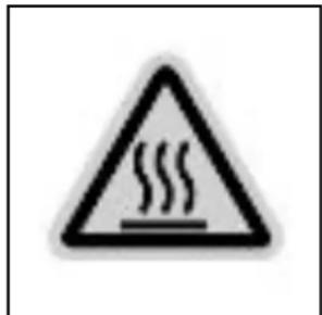
RISK OF BURNS | Serious injury could occur from touching exposed metal parts. These areas can remain hot for some time after the air compressor is shutdown. | Never allow any part of your body or other materials to make contact with any exposed metal parts on the air compressor, motor, or pipework. |
RISK OF FLYING OBJECTS EYE PROTECTION MUST BE WORN EYE PROTECTION MUST BE WORN | Soft tissue damage can occur from the compressed air stream.Serious injury can occur from loose debris being propelled at a high speed from the compressed air stream. | Always wear OSHA required Z87 safety glasses to shield the eyes from flying debris.Never point the air stream at any part of your body, anyone else or animals.Never leave pressurized air compressor unattended. Shut off air compressor and relieve pressure before attempting maintenance, attaching tools or accessories.Always maintain a safe distance from people and animals while operating the air compressor.Do not move the air compressor while air tank is under pressure. Do not attempt to move the air compressor by pulling on the hose. |
RISK FROM MOVING PARTS WARNING: UNIT MAY START WITHOUT WARNING WARNING: UNIT MAY START WITHOUT WARNING | Risk of bodily injury from moving parts. This air compressor cycles automatically when the pressure switch is in the On/Auto position.Risk of injury from negligent use. | Always turn off air compressor when not in use. Bleed pressure from the air hose and unplug from electrical outlet before performing maintenance. All repairs to the air compressor should be made by an Authorized Service person. Never assume the air compressor is safe to work on just because it is not operating. It could restart at any time!Do not operate without protective covers/guards. Replace damaged covers/guards before using the air compressor. |
RISK FROM NEGLIGENCE | Never allow children or adolescents to operate this air compressor!Stay alert-watch what you are doing. Do not operate the air compressor when fatigued or under the influence of alcohol or drugs.Know how to stop the air compressor. Be thoroughly familiar with controls. | |
| RISK OF AIR COMPRESSOR DAMAGE | Risk of major repair. | Do not operate air compressor without an air filter.Do not operate air compressor in a corrosive environment.Always operate the air compressor in a stable, secure position to prevent air compressor from falling.Follow all maintenance instructions listed in this manual.Do not operate air compressor prior to adding oil. |
! SAVE THESE INSTRUCTIONS !
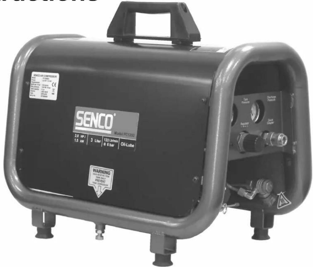
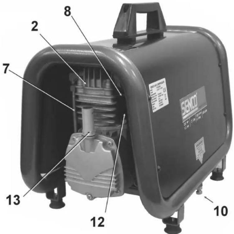
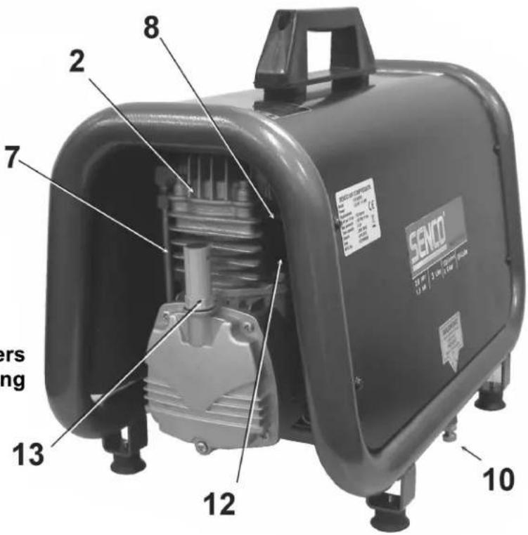
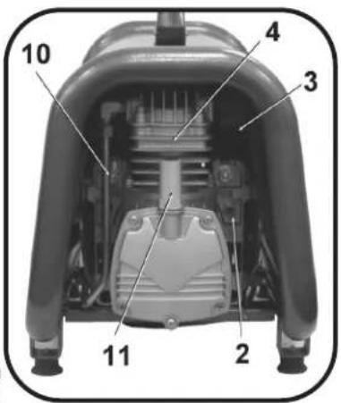
COMPRESSOR FEATURES
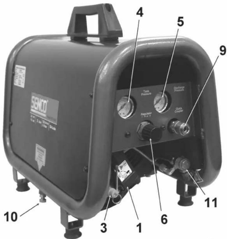
- Motor/Pressure Switch
- Air Compressor Pump
- Safety Relief Valve
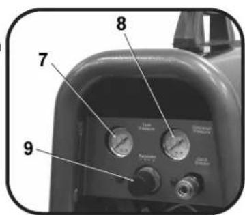
- Tank Pressure Gauge
- Outlet Pressure Gauge
- Pressure Regulator
- Discharge Liner
- Air filter
- Quick Disconnector
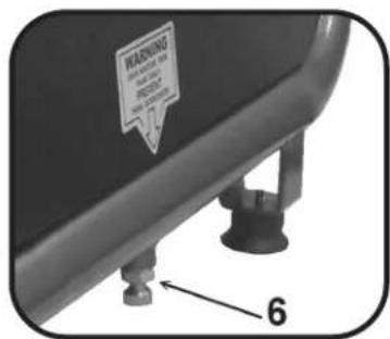
- Tank Drain Valve
- Cold start Valve
- Overload / reset
- Dipstick
COMPRESSOR FEATURES
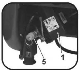
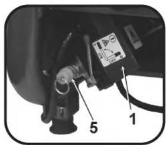
1) MOTOR/PRESSURE SWITCH: This switch is used to start or stop the air compressor. Moving the switch to the On (1) position will provide automatic power to the pressure switch which will allow the motor to start when the air tank pressure is below the factory set cut-in pressure. When in the On (1), the pressure switch stops the motor when the air tank pressure reaches the factor set cut-out pressure. For safety purposes, this switch also has a pressure release valve located on the side of the switch designed to automatically release compressed air from the air compressor pump head and its discharge line when the air compressor reaches cut-out pressure or is shut off. This allows the motor to restart freely. Moving the switch to the Off position will remove power from the pressure switch and stop the air compressor.
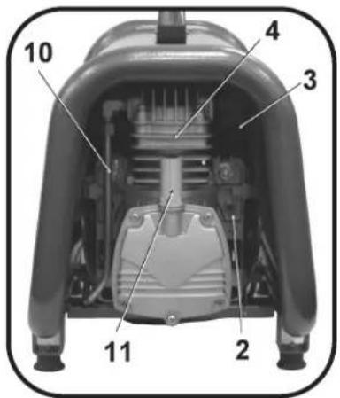
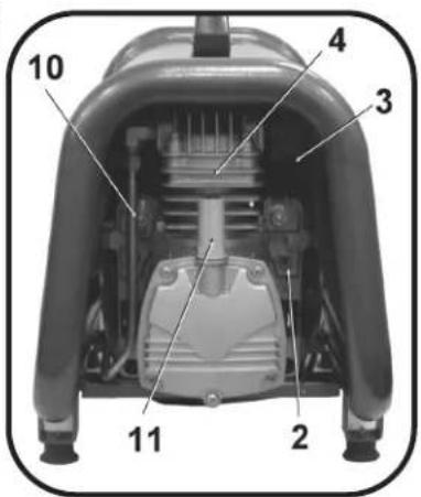
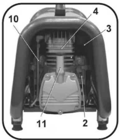
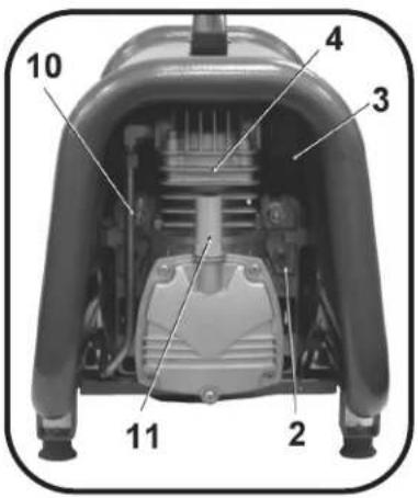
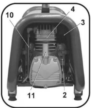
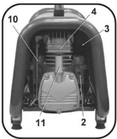
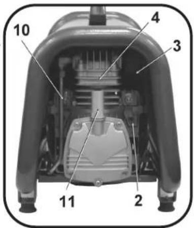
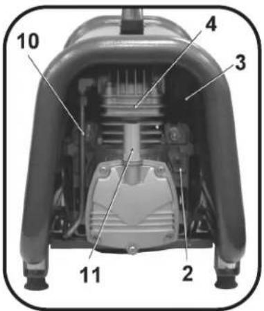
2) MOTOR THERMAL OVERLOAD: The electric motor has a thermal overload protector. If the motor overheats for any reason, the thermal overload will cut off power, thus preventing the motor from being damaged. Wait until the motor is cool. Motor also has a magnetic breaker. Reset switch if it is tripped.
3) AIR INTAKE FILTER: This filter is designed to clean air coming into the pump. To ensure the pump continually receives a clean, cool, dry air supply this filter must always be clean and ventilation opening free from obstructions. The filter can be removed for cleaning by using warm, soapy water. Rinse the filter and air dry.
4) AIR COMPRESSOR PUMP: To compress air, the piston moves up and down in the cylinder. On the downstroke, air is drawn in through the air intake valve while the exhaust valve remains closed. On the upstroke, air is compressed, the intake valve closes and compressed air is forced out through the exhaust valve, into the discharge line, through the check valve and into the air tank.
5) SAFETY RELIEF VALVE: This valve is designed to prevent system failures by relieving pressure from the system when the compressed air reaches a predetermined level. The valve is preset by the manufacturer and must not be modified in any way. To verify the valve is working properly, pull on the ring. Air pressure should escape. When the ring is released, it will reseat.
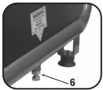
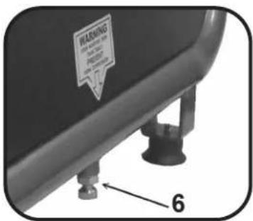
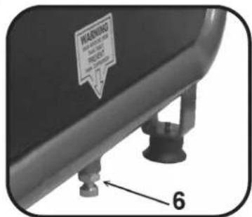
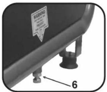
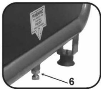
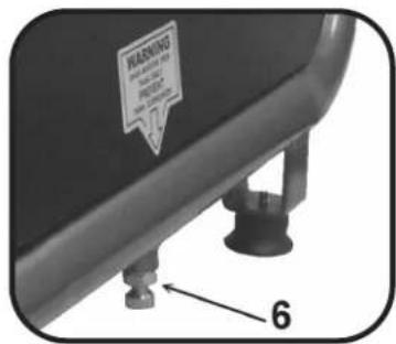
6) AIR TANK DRAIN VALVE: The drain valve is used to remove moisture from the air tank(s) after the air compressor is shut off. NEVER attempt to open the drain valve when more than 0.7 bar of air pressure is in the air tank! To open the drain valve, turn the knob counterclockwise. Tilt tank to ensure that all condensation drains through valve.
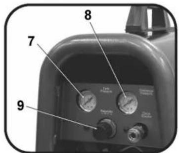
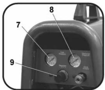
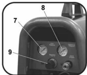
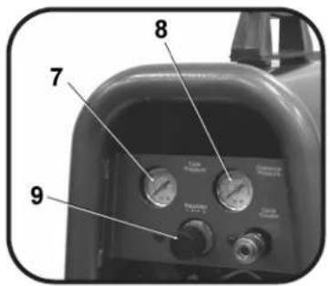
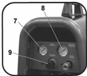
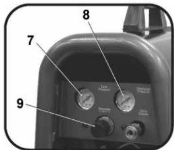
7) AIR TANK PRESSURE GAUGE: The air tank pressure gauge indicates the reserve air pressure in the air tank (s).
8) OUTLET PRESSURE GAUGE: The outlet pressure gauge indicates the air pressure available at the outlet side of the regulator. This pressure is controlled by the regulator and is always less or equal to the air tank pressure.
9) PRESSURE REGULATOR: The air pressure coming from the air tank is controlled by the regulator knob. Turn the pressure regulation knob clockwise to increase discharge pressure, and counterclockwise to decrease discharge pressure.
10) DISCHARGE LINE: Please note that the discharge line is very hot. HOT SURFACES: Do not remove protective shroud. High temperature after sustained use.
11) DIPSTICK: The dipstick will measure the amount of oil in the pump. Oil level should be checked on a daily basis to ensure that it is between the minimum and maximum notch. Air escaping from the vent is normal.

PREPARATION
INITIAL SET-UP:
- Read safety warnings before setting-up air compressor .
- Add entire contents of oil from enclosed bottle prior to starting compressor
- Ensure the oil level is above the minimum notch and below the maximum notch on the dipstick. If low, add compressor pump oil.
LOCATION:
CAUTION
In order to avoid damaging the air compressor, do not incline the air compressor transversely or longitudinally more than 10^ .
- Place air compressor at least 30 cm away from obstacles that may prevent proper ventilation.
Do not place air compressor in an area:
-where there is evidence of oil or gas leaks.
-where flammable gas vapors or materials may be present.

WARNING
Serious injury or death may occur if electrical sparks from motor and pressure switch come in contact with flammable vapors, combustible dust, gases or other combustible materials. When using the air compressor for spray painting, place the pressor as far away I from the work area as possible, using extra air hoses instead of on cords.
-where air temperatures fall below 0^ C or exceed 40^ C.
-where extremely dirty air or water could be drawn into the air compressor.
ELECTRICAL:

DANGER
Improper connection of the equipment-grounding conductor can result in a risk of shock or electrocution. Check with a qualified electrician or service personnel
if you are in doubt as to whether the outlet is properly grounded. Do not use any type of adapter with this product. If repair or replacement of the cord or plug is necessary, do not connect the grounding wire to either flat blade terminal. The wire with insulation having an outer surface that is green with or without yellow stripes is the grounding wire.

WARNING
This product must be grounded. If there should be a malfunction or breakdown, grounding provides a path of least resistance for electric current to reduce the risk of electric shock. This product is equipped with a cord having an equipment
grounding conductor and a grounding type plug. The plug must be plugged into an appropriate outlet that is properly installed and grounded in accordance with all local codes and ordinances.
- SENCO® DOES NOT RECOMMEND THE USE OF EXTENSION CORDS as this can create power loss and overheating of the motor. Use of an additional air hose is recommended rather than an extension cord. If use of an extension cord is unavoidable, it should be plugged into a GFCI found in circuit boxes or protected receptacles. When using an extension cord, observe the following:
Cable Length Wire Gauge
Up to 8 meters 12 AWG
Up to 30 meters
Up to 50 meters
Up to 75 meters
10 AWG
8 AWG
6 AWG
Use only 3-blade extension cords that have 3-blade grounding-type plugs and 3-slot cord connectors that will accept the plug from the product. Use only extension cords having an electrical rating not less than the rating of the product. Do not use damaged extension cords. Examine extension cord before using and replace if damaged. Do not abuse extension cord and do not yank on any cord to disconnect. Keep cord away from heat and sharp edges. Always shut off the air compressor switch before removing the plug from the receptacle.
OPERATION
PRE-START CHECKLIST:
- Remove any moisture in the air compressor air tank. Remove excessive pressure with an air tool, then open the air tank drain valve in the bottom of the air tank. Close tightly when drained.

WARNING: Risk of bodily injury. NEVER attempt to open the drain valve when more than 0.7 bar of air pressure is in the air tank!
- Make sure the air compressor Motor Switch is in the OFF (0) position.
- Make sure all safety valves are working correctly.
- Make sure all guards and covers are in place and securely mounted.
START-UP:
- Ensure the lever on the pressure switch box is in the OFF (0) position.
- Plug the power cord into a grounded outlet.
- Move the lever on the pressure switch box to the On (1) position.
- AUTO OPERATION: The ON position will allow the air compressor to START building up pressure in the air tanks and STOP when correct pressure is achieved. When pressure drops with usage, the air compressor will START building up pressure again.
- Set pressure by adjusting the pressure regulator knob counterclockwise for less pressure and clockwise for more pressure.
- If you notice any unusual noise or vibration, stop the air compressor and refer to Troubleshooting.
SHUTDOWN:
- To stop the air compressor, move the lever on the pressure switch box to the OFF (0) position. NEVER stop the air compressor by unplugging it from the power source. This could result in risk of electrocution.
- Drain air from the air tank by releasing air with an attached air tool or by pulling on the safety relief valve ring.
- Once pressure in the air tanks register under 0.7 bar, open the drain valve under each air tank to drain any moisture.
- Allow the air compressor to cool down.
- Wipe air compressor clean and store in a safe, non-freezing area.
MAINTENANCE
Read the instruction manual before performing maintenance. The following procedures must be performed when stopping the air compressor for maintenance or service.
- Turn off air compressor.


WARNING: Never assume the air compressor is safe to work on just because it is not operating. It could restart at any time!
- Disconnect cord from main power supply.
- Open all drains.
- Wait for the air compressor to cool before starting service.
MAINTENANCE CHART
| PROCEDURE | DAILY | WEEKLY | MONTHLY | 200 HOURS |
| Check pump oil level | X | |||
| Oil leak inspection | X | |||
| Drain condensation in air tank(s) | X | |||
| Check for unusual noise/vibration | X | |||
| Check for air leaks | X | |||
| Inspect air filter | X | |||
| Clean exterior of compressor | X | |||
| Check safety relief valve | X | |||
| Change pump oil* | X | |||
| Replace air filter | X |
*The pump oil must be changed after the first 50 hours of operation and every 200 hours or 3 months, whichever comes first. Recommended non-detergent straight weights.
TROUBLESHOOTIN G
Symptom 1. Motor will not run or restart.
| Power cord not plugged in. | Plug cord into grounded outlet. |
| Motor/Pressure switch in OFF (0) position. | Move switch to ON (1) position. |
| Motor thermal overload switch has tripped. | Turn air compressor off, wait until motor is cool, then check motor circuit breaker. |
| Fuse blown or circuit breaker has tripped. | Replace fuse or reset circuit breaker. |
| Check for proper fuse amperage. | |
| Check for low voltage conditions. | |
| Disconnect any other electrical appliances from circuit or operate air compressor on its own branch circuit. | |
| Wrong gauge wire or length of extension cord. | Check chart on page #10 for proper gauge wire and cord length. |
| Air tank pressure exceeds motor/ pressure switch cut-in pressure. | Motor will start automatically when air tank pressure drops below cut-in pressure of motor/pressure switch. |
| Pressure release valve on motor/ pressure switch has not unloaded pump head pressure. | Bleed the line by moving the switch to the Off (0) position. |
| Defective motor, motor capacitor, motor/ pressure switch, or check valve. | Contact Senco Customer Service. |
Symptom 2. When in the Start/Stop option, motor runs continuously.
| PROBABLE CAUSEMotor/Pressure switch does not shut off motor when air compressor reaches cut-out pressure and safety relief valve activates. | REMEDYMove the motor/pressure switch to the Off (0) positionIf the motor doesn t shutoff, unplug the air compressor.If the electrical contacts are welded together, replace the pressure switch. |
| Air compressor is incorrectly sized. | Limit the air pressure to the capacity of the air compressor. Either use a smaller tool or a larger air compressor. |
Symptom 3. Air continues to leak at motor/pressure switch release valve after motor stops.
| PROBABLE CAUSEThe check valve is stuck open. | REMEDYRemove, clean or replace. |
TROUBLESHOOTING
| Symptom 4. Air continues to leak at motor/pressure switch release valve while motor is running. | |
| PROBABLE CAUSE | REMEDY |
| Defective motor/pressure switch. | Replace. |
Symptom 5. Air leaks from safety relief valve.
| PROBABLE CAUSEPossible defective safety relief valve. | REMEDYOperate safety relief valve manually by pulling on ring.If it still leaks, it should be replaced. |
| Excessive air tank pressure. | Defective motor/pressure switch. Replace. |
Symptom 6. Air leaks at fittings.
| PROBABLE CAUSEFittings are not tight enough. | REMEDYTighten fittings where air can be heard escaping. Check fittings with soapy water solution.Do not overtighten. |
Symptom 7. Air leak in air tank.
| PROBABLE CAUSEDefective or rusted air tank. | REMEDYAir tank must be replaced. Do not attempt to repair air tank! Do not weld, repair or make modifications. |
Symptom 8. Air blowing from inlet filter.
| PROBABLE CAUSE | REMEDY |
| Damaged inlet (reed) valve. | Contact SENCO Customer Service |
Symptom 9. Insufficient pressure at air tool or accessory.
| PROBABLE CAUSEPressure regulator knob not turned to high enough pressure or defective pressure regulator. | REMEDYAdjust pressure regulator knob to proper setting or replace. |
| Restricted air intake filter. | Clean. |
| Air leaks. | Check for leaks and repair. |
| Air compressor is not large enough for air requirement. | Check the accessory air requirement. If it is higher than the CFM or pressure supply of the air compressor, you need a larger air compressor. |
TROUBLESHOOTING
Symptom 10. Air compressor not making enough air.
PROBABLE CAUSE
Restricted air intake filter.
Defective (reed) valve.
REMEDY
Clean.
Drain air tank and measure pump up time. Compare to specifications. If lower, remove pump head and inspect valve plate, clean or replace.
Symptom 11. Moisture in discharge air.
PROBABLE CAUSE
Condensation in air tank caused by high level of atmospheric humidity or air compressor is not run long enough.
REMEDY
Drain air tank after every use. Drain air tank more often in humid weather and use an air line filter.
MODEL : PC1252
PX馬達
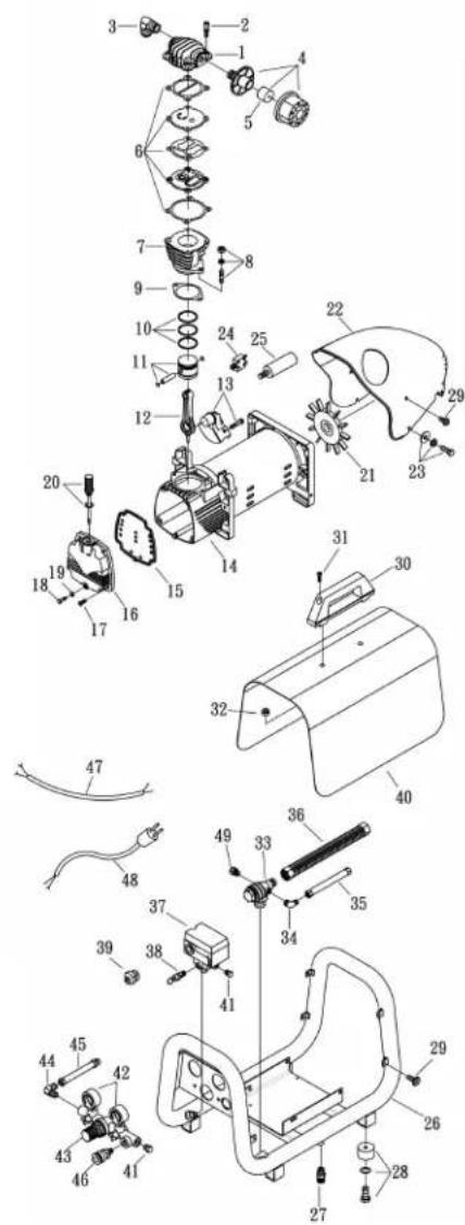
SPARE PARTS LIST
NO:RLB-1311
| REF. NO. | DESCRIPTION | PART NO. | QTY. |
| 1 | Cylinder head | 3101061 | 1 |
| 2 | Allen bolt set | 3B01-M06*040V | 4 |
| 3 | Exhaust elbow | 2N06-03T03H | 1 |
| 4 | Air filter | 2140023ARS | 1 |
| 5 | Filter element | 2142017 | 1 |
| 6 | In.& Ex.valve assembly | 3B13-AC0747 | 1 |
| 7 | Cylinder | 3201066 | 1 |
| 8 | Double head screw set | 3B11-008-A | 2 |
| 9 | Cylinder gasket | 2G04-015 | 1 |
| 10 | Piston ring set | 3B32-47N | 1 |
| 11 | Piston set | 3B31-47 | 1 |
| 12 | Rod | 2315055X | 1 |
| 13 | Crankshaft & balancer | 3304081 | 1 |
| 14 | Motor set | 3B8-XD2006 | 1 |
| 15 | Front cover gasket | 2G07-010A | 1 |
| 16 | Front cover | 3309024 | 1 |
| 17 | Bolt | 2B02-FM6*015 | 4 |
| 18 | Bolt | 2B02-FM6*035 | 1 |
| 19 | O-ring | 2N52-P06 | 1 |
| 20 | Dipstick set | 2339008ARS | 1 |
| 21 | Cooling fan | 2336037-2 | 1 |
| 22 | Shroud | 2428014RS | 1 |
| 23 | Bolt | 3B00-SM06*020VW | 4 |
| 24 | Circuit breaker | 2E25-10AS | 1 |
| 25 | Running capacitor | 2E27-030S45X45 | 1 |
| 26 | Air tank | 3401735 | 1 |
| 27 | Drain valve | 2405012 | 2 |
| 28 | Rubber pad set | 3433011-ARS | 4 |
| 29 | Bolt | 2B02-FM5*010WB | 14 |
| 30 | Grip | 3432005 | 1 |
| 31 | Allen bolt | 2B01-M06*025 | 2 |
| 32 | U-nut | 2B21-FM06 | 2 |
| 33 | Check valve | 2414037X | 1 |
| 34 | Unloading tube | 2N06-01T02H | 1 |
| 35 | Unloading tube set | 3B2-02*170F | 1 |
| 36 | Exhaust tube set | 3B2-03*510N | 1 |
| 37 | Pressure switch | 2E21-BA266APS | 1 |
| 38 | Pressure relief valve | 2406018CE | 1 |
| 39 | Strain relief bushing | 2E04-008 | 3 |
| 40 | Shroud | 3420069 | 1 |
| 41 | Plug | 2B14-ST02E | 3 |
| 42 | Pressure gauge | 2D12-15V14BAR | 2 |
| 43 | Exhaust manifold | 2408012RS | 1 |
| 44 | Elbow | 2N06-02T02SRS | 1 |
| 45 | Tube | 2T06-030RS | 1 |
| 46 | Quick coupler | 07S1/4M-ERS | 1 |
| 47 | Cable | 2E02-2C30602Y2T | 1 |
| 48 | Power cable | 2E01-029 | 1 |
| 49 | Auto relief valve | 2409010 | 1 |
SPECIFICATIONS
| Model # | PC1252 |
| Motor | |
| Horsepower | 2.0 HP / 1.5 KW |
| Voltage | 230V |
| Amperage | 10A |
| Hz. | 50 |
| Phase | Single |
| RPM | 2850 |
| Compressor Pump | |
| Number of Cylinders | 1 |
| Compressor Stage | 1 |
| Lubrication | Oil-lube |
| Oil Type | SENCO PC0344 |
| Crankcase | Aluminium |
| Bearings | Ball |
| Cylinder | Aluminium/Steel Sleeve |
| Valves | Reed-Single |
| Head | Aluminium |
| Filter | Canister |
| Motor/Pressure Switch Setting | |
| Cut-out | 9 Bar |
| Cut-in | 7 Bar |
| Control | On (1) / Off (0) |
| Air tank | |
| Capacity | 3 liter |
| Performance | |
| Air Displacement L/min | 198 L/min (7.06 CFM) |
| Air flow @ 6 bar L/min | 82 L/min (4.69 CFM) |
| Maximum Pressure | 9 Bar |
| Pump-up time: 0-9 Bar | 15 sec. |
| Recovery time: 7-9 bar | 4 sec. |
| Weight | |
| Net. | 22.5 kg |
| Dimensions | |
| Basic L x W x H | 54x32x46cm |
| Measured sound power level [dB] | 88 dBA |
Guaranteed sound power level [dB] 90 dBA
SENCO COMPRESSOR AND PARTS WARRANTY
This compressor has been designed and constructed using the highest standards of material and workmanship.
COMPRESSOR WARRANTY:
The length of this guarantee is 1 year from date of purchase by the original retail purchaser. During this period, Senco Products, Inc., will repair or replace at Senco's option, any original part or parts for the original retail purchaser. This will be done free of charge, provided the parts are determined defective in materials or workmanship upon examination by a Senco Authorized Warranty Service Center, with the exceptions and exclusions described below. Any replacement part provided will carry a warranty for the balance of the period of warranty applicable to the part it replaces. When repair or replacement of parts or compressor is necessary, the original retail purchaser returns the complete compressor or part, with transportation prepaid, to the nearest Senco Authorized Warranty Service Center, with purchase receipt or other positive proof that the part or compressor is within the warranty period.
Senco warrants all parts of your Senco air compressor to be free from defects in materials and workmanship during the following periods:
Defective parts not subject to normal wear and tear will be repaired or replaced, at our (Senco's) option, during warranty period. In any event, reimbursement is limited to the purchase price paid.
EXCLUSIONS:
- This warranty does not cover parts damaged due to normal wear, misapplication, misuse, accidents, operation at other than recommended speeds or voltage (electric units only), improper storage, or damages resulting during shipping.
- Deviation from operating instructions, specifications, and maintenance schedules.
- Labor charges, loss or damage resulting from improper operation, maintenance or repairs made by person(s) other than a Senco Authorized Warranty Service Center.
- The use of other than genuine Senco Repair Parts will void warranty.
This warranty is contingent upon proper use of the compressor by purchaser and does not cover:
(A) Abnormal conditions, accident, neglect, misuse or improper storage of the unit.
(B) Deviation from operating or maintenance instructions.
(C) Modifications not authorized by Senco.
(D) Repairs or maintenance (other than routine air tank draining required by your operating and maintenance manual) made by persons other than Senco or its authorized agents.
(E) Freight damage.
THIS WARRANTY IS THE ONLY WARRANTY ON THIS COMPRESSOR, AND ALL OTHER WARRANTIES, WHETHER ORAL, WRITTEN, EXPRESS, OR IMPLIED, INCLUDING, BUT NOT LIMITED TO, THE IMPLIED WARRANTY OF MERCHANTABILITY OR FITNESS FOR A PARTICULAR PURPOSE, ARE EXCLUDED. BUYER S OR USER S REMEDIES ARE SOLELY AND EXCLUSIVELY AS STATED ABOVE. SENCO PRODUCTS, INC. SHALL IN NO EVENT BE LIABLE FOR INCIDENTAL, CONSEQUENTIAL, INDIRECT, OR SPECIAL DAMAGES. IN NO EVENT, WHETHER AS A RESULT OF A BREACH OF CONTRACT, WARRANTY, TORT (INCLUDING NEGLIGENCE) OR OTHERWISE, SHALL SENCO S LIABILITY EXCEED THE PRICE OF THE COMPRESSOR WHICH HAS GIVEN RISE TO THE CLAIM OR LIABILITY. ANY LIABILITY CONNECTED WITH THE USE OF THIS COMPRESSOR SHALL TERMINATE UPON THE EXPIRATION OF THE WARRANTY PERIOD SPECIFIED ABOVE.
Replacement of Compressor Due to Natural Disaster
Senco will also replace any compressor destroyed by an Act of God such as flood, earthquake, hurricane or other disaster resulting only from the forces of nature. Such a claim will be honored provided that such original retail purchaser had previously submitted a completed warranty registration card, and then submits proof of ownership and an acceptable statement describing such Act of God documented by an insurance carrier, police department, or other official governmental source.

SENCO
2010 by Verpa-Senco BV
PC1252 Rev. 000000000


PIÈCES EN MOUVEMENT 7
NÉGLIGENCE 7
DOMMAGES AU COMPRESSEUR 7
CARACTÉRISTIQUES DU COMPRESSEUR 8
PRÉPARATION.... 10
MISE EN ŒUVRE INITIALE 10
EMPLACEMENT 10
ALIMENTATION ÉLECTRIQUE 10
FONCTIONNEMENT.... 11
LISTE DE VÉRIFICATIONS PRÉLIMINAIRES......11
DÉMARRAGE 11
COUPURE 11
ENTRETIEN ....11
DÉPANNAGE 12-14
SPÉCIFICATIONS .... 15
GARANTIE 16
INTRODUCTION
natural_image
Black and white illustration of a hand with a lightning bolt symbol (no text or numbers)
natural_image
Warning symbol of a lightning bolt inside a triangle (no text or numbers)CONSEQUENCES POTENTIELLES

PRÉPARATION
MISE EN ŒUVRE INITIALE :
| PROCEDURE | DAILY | WEEKLY | MONTHLY | 200 HOURS |
| Check pump oil level X | ||||
| Oil leak inspection X | ||||
| Drain condensation in air tank(s) X | ||||
| Check for unusual noise/vibration X | ||||
| Check for air leaks X | ||||
| Inspect air filter X | ||||
| Clean exterior of compressor X | ||||
| Check safety relief valve X | ||||
| Change pump oil* | X | |||
| Replace air filter | X |
*The pump oil must be changed after the first 50 hours of operation and every 200 hours or 3 months, whichever comes first. Recommended non-detergent straight weights.
DÉPANNAGE
PX馬達
SPARE PARTS LIST
NO:RLB-1311
| REF. NO. | DESCRIPTION | PART NO. | QTY. |
| 1 | Cylinder head | 3101061 | 1 |
| 2 | Allen bolt set | 3B01-M06*040V | 4 |
| 3 | Exhaust elbow | 2N06-03T03H | 1 |
| 4 | Air filter | 2140023ARS | 1 |
| 5 | Filter element | 2142017 | 1 |
| 6 | In.& Ex.valve assembly | 3B13-AC0747 | 1 |
| 7 | Cylinder | 3201066 | 1 |
| 8 | Double head screw set | 3B11-008-A | 2 |
| 9 | Cylinder gasket | 2G04-015 | 1 |
| 10 | Piston ring set | 3B32-47N | 1 |
| 11 | Piston set | 3B31-47 | 1 |
| 12 | Rod | 2315055X | 1 |
| 13 | Crankshaft & balancer | 3304081 | 1 |
| 14 | Motor set | 3B8-XD2006 | 1 |
| 15 | Front cover gasket | 2G07-010A | 1 |
| 16 | Front cover | 3309024 | 1 |
| 17 | Bolt | 2B02-FM6*015 | 4 |
| 18 | Bolt | 2B02-FM6*035 | 1 |
| 19 | O-ring | 2N52-P06 | 1 |
| 20 | Dipstick set | 2339008ARS | 1 |
| 21 | Cooling fan | 2336037-2 | 1 |
| 22 | Shroud | 2428014RS | 1 |
| 23 | Bolt | 3B00-SM06*020VW | 4 |
| 24 | Circuit breaker | 2E25-10AS | 1 |
| 25 | Running capacitor | 2E27-030S45X45 | 1 |
| 26 | Air tank | 3401735 | 1 |
| 27 | Drain valve | 2405012 | 2 |
| 28 | Rubber pad set | 3433011-ARS | 4 |
| 29 | Bolt | 2B02-FM5*010WB | 14 |
| 30 | Grip | 3432005 | 1 |
| 31 | Allen bolt | 2B01-M06*025 | 2 |
| 32 | U-nut | 2B21-FM06 | 2 |
| 33 | Check valve | 2414037X | 1 |
| 34 | Unloading tube | 2N06-01T02H | 1 |
| 35 | Unloading tube set | 3B2-02*170F | 1 |
| 36 | Exhaust tube set | 3B2-03*510N | 1 |
| 37 | Pressure switch | 2E21-BA266APS | 1 |
| 38 | Pressure relief valve | 2406018CE | 1 |
| 39 | Strain relief bushing | 2E04-008 | 3 |
| 40 | Shroud | 3420069 | 1 |
| 41 | Plug | 2B14-ST02E | 3 |
| 42 | Pressure gauge | 2D12-15V14BAR | 2 |
| 43 | Exhaust manifold | 2408012RS | 1 |
| 44 | Elbow | 2N06-02T02SRS | 1 |
| 45 | Tube | 2T06-030RS | 1 |
| 46 | Quick coupler | 07S1/4M-ERS | 1 |
| 47 | Cable | 2E02-2C30602Y2T | 1 |
| 48 | Power cable | 2E01-029 | 1 |
| 49 | Auto relief valve | 2409010 | 1 |
SPÉCIFICATIONS
Guaranteed sound power level [dB] 90 dBA
GARANTIE SENCO POUR LE COMPRESSEUR ET LES PIÈCES
2010 by Verpa-Senco BV
PC1252 Rev. 000000000

natural_image
Black and white illustration of a hand with lightning bolts and a broken rope (no text or symbols)
natural_image
Warning symbol of a lightning bolt inside a triangle (no text or numbers)natural_image
Abstract black-and-white graphic of a stylized human figure with geometric patterns (no text or symbols)RIESGO DE
QUEMADURAS
natural_image
Silhouette of a person running with arrows indicating motion or effort (no text or symbols)natural_image
Simple icon of a person wearing glasses inside a circle (no text or symbols)POTENTIAL CONSEQUENCE

PREPARACIÓN
MONTAJE INICIAL:
| PROCEDURE DAILY WEEKLY MONTHLY 200 HOURS | ||||
| Check pump oil level X | ||||
| Oil leak inspection X | ||||
| Drain condensation in air tank(s) X | ||||
| Check for unusual noise/vibration X | ||||
| Check for air leaks X | ||||
| Inspect air filter X | ||||
| Clean exterior of compressor X | ||||
| Check safety relief valve X | ||||
| Change pump oil* | X | |||
| Replace air filter | X | |||
*The pump oil must be changed after the first 50 hours of operation and every 200 hours or 3 months, whichever comes first. Recommended non-detergent straight weights.
PX馬達
SPARE PARTS LIST
NO:RLB-1311
| REF. NO. | DESCRIPTION | PART NO. | QTY. |
| 1 | Cylinder head | 3101061 | 1 |
| 2 | Allen bolt set | 3B01-M06*040V | 4 |
| 3 | Exhaust elbow | 2N06-03T03H | 1 |
| 4 | Air filter | 2140023ARS | 1 |
| 5 | Filter element | 2142017 | 1 |
| 6 | In.& Ex.valve assembly | 3B13-AC0747 | 1 |
| 7 | Cylinder | 3201066 | 1 |
| 8 | Double head screw set | 3B11-008-A | 2 |
| 9 | Cylinder gasket | 2G04-015 | 1 |
| 10 | Piston ring set | 3B32-47N | 1 |
| 11 | Piston set | 3B31-47 | 1 |
| 12 | Rod | 2315055X | 1 |
| 13 | Crankshaft & balancer | 3304081 | 1 |
| 14 | Motor set | 3B8-XD2006 | 1 |
| 15 | Front cover gasket | 2G07-010A | 1 |
| 16 | Front cover | 3309024 | 1 |
| 17 | Bolt | 2B02-FM6*015 | 4 |
| 18 | Bolt | 2B02-FM6*035 | 1 |
| 19 | O-ring | 2N52-P06 | 1 |
| 20 | Dipstick set | 2339008ARS | 1 |
| 21 | Cooling fan | 2336037-2 | 1 |
| 22 | Shroud | 2428014RS | 1 |
| 23 | Bolt | 3B00-SM06*020VW | 4 |
| 24 | Circuit breaker | 2E25-10AS | 1 |
| 25 | Running capacitor | 2E27-030S45X45 | 1 |
| 26 | Air tank | 3401735 | 1 |
| 27 | Drain valve | 2405012 | 2 |
| 28 | Rubber pad set | 3433011-ARS | 4 |
| 29 | Bolt | 2B02-FM5*010WB | 14 |
| 30 | Grip | 3432005 | 1 |
| 31 | Allen bolt | 2B01-M06*025 | 2 |
| 32 | U-nut | 2B21-FM06 | 2 |
| 33 | Check valve | 2414037X | 1 |
| 34 | Unloading tube | 2N06-01T02H | 1 |
| 35 | Unloading tube set | 3B2-02*170F | 1 |
| 36 | Exhaust tube set | 3B2-03*510N | 1 |
| 37 | Pressure switch | 2E21-BA266APS | 1 |
| 38 | Pressure relief valve | 2406018CE | 1 |
| 39 | Strain relief bushing | 2E04-008 | 3 |
| 40 | Shroud | 3420069 | 1 |
| 41 | Plug | 2B14-ST02E | 3 |
| 42 | Pressure gauge | 2D12-15V14BAR | 2 |
| 43 | Exhaust manifold | 2408012RS | 1 |
| 44 | Elbow | 2N06-02T02SRS | 1 |
| 45 | Tube | 2T06-030RS | 1 |
| 46 | Quick coupler | 07S1/4M-ERS | 1 |
| 47 | Cable | 2E02-2C30602Y2T | 1 |
| 48 | Power cable | 2E01-029 | 1 |
| 49 | Auto relief valve | 2409010 | 1 |
ESPECIFICACIONES
Guaranteed sound power level [dB] 90 dBA
GARANTIA SENCO PARA EL COMPRESOR Y LAS PIEZAS
2010 by Verpa-Senco BV
PC1252 Rev.

KOMPRESSORFUNKTIONER....8
FORBEREDELSE....10
INDLEDENDE INSTALLATION....10
PLACERING....10
ELEKTRISK....10
DRIFT....11
KONTROLLISTE F∅R START 11
OPSTART....11
AFBRYDELSE....11
VEDLIGEHOLDELSE ....11
FEJLAFHJÆLPNING....12-14
SPECIFICATIONER....15
GARANTI....16
INDLEDNING

FORBEREDELSE
INDLEDENDE INSTALLERING:
| PROCEDURE | DAILY | WEEKLY | MONTHLY | 200 HOURS |
| Check pump oil level X | ||||
| Oil leak inspection X | ||||
| Drain condensation in air tank(s) | X | |||
| Check for unusual noise/vibration | X | |||
| Check for air leaks | X | |||
| Inspect air filter | X | |||
| Clean exterior of compressor | X | |||
| Check safety relief valve | X | |||
| Change pump oil* | X | |||
| Replace air filter | X |
PX馬達
SPARE PARTS LIST
NO:RLB-1311
| REF. NO. | DESCRIPTION | PART NO. | QTY. |
| 1 | Cylinder head | 3101061 | 1 |
| 2 | Allen bolt set | 3B01-M06*040V | 4 |
| 3 | Exhaust elbow | 2N06-03T03H | 1 |
| 4 | Air filter | 2140023ARS | 1 |
| 5 | Filter element | 2142017 | 1 |
| 6 | In.& Ex.valve assembly | 3B13-AC0747 | 1 |
| 7 | Cylinder | 3201066 | 1 |
| 8 | Double head screw set | 3B11-008-A | 2 |
| 9 | Cylinder gasket | 2G04-015 | 1 |
| 10 | Piston ring set | 3B32-47N | 1 |
| 11 | Piston set | 3B31-47 | 1 |
| 12 | Rod | 2315055X | 1 |
| 13 | Crankshaft & balancer | 3304081 | 1 |
| 14 | Motor set | 3B8-XD2006 | 1 |
| 15 | Front cover gasket | 2G07-010A | 1 |
| 16 | Front cover | 3309024 | 1 |
| 17 | Bolt | 2B02-FM6*015 | 4 |
| 18 | Bolt | 2B02-FM6*035 | 1 |
| 19 | O-ring | 2N52-P06 | 1 |
| 20 | Dipstick set | 2339008ARS | 1 |
| 21 | Cooling fan | 2336037-2 | 1 |
| 22 | Shroud | 2428014RS | 1 |
| 23 | Bolt | 3B00-SM06*020VW | 4 |
| 24 | Circuit breaker | 2E25-10AS | 1 |
| 25 | Running capacitor | 2E27-030S45X45 | 1 |
| 26 | Air tank | 3401735 | 1 |
| 27 | Drain valve | 2405012 | 2 |
| 28 | Rubber pad set | 3433011-ARS | 4 |
| 29 | Bolt | 2B02-FM5*010WB | 14 |
| 30 | Grip | 3432005 | 1 |
| 31 | Allen bolt | 2B01-M06*025 | 2 |
| 32 | U-nut | 2B21-FM06 | 2 |
| 33 | Check valve | 2414037X | 1 |
| 34 | Unloading tube | 2N06-01T02H | 1 |
| 35 | Unloading tube set | 3B2-02*170F | 1 |
| 36 | Exhaust tube set | 3B2-03*S10N | 1 |
| 37 | Pressure switch | 2E21-BA266APS | 1 |
| 38 | Pressure relief valve | 2406018CE | 1 |
| 39 | Strain relief bushing | 2E04-008 | 3 |
| 40 | Shroud | 3420069 | 1 |
| 41 | Plug | 2B14-ST02E | 3 |
| 42 | Pressure gauge | 2D12-15V14BAR | 2 |
| 43 | Exhaust manifold | 2408012RS | 1 |
| 44 | Elbow | 2N06-02T02SRS | 1 |
| 45 | Tube | 2T06-030RS | 1 |
| 46 | Quick coupler | 07S1/4M-ERS | 1 |
| 47 | Cable | 2E02-2C30602Y2T | 1 |
| 48 | Power cable | 2E01-029 | 1 |
| 49 | Auto relief valve | 2409010 | 1 |
SPECIFICATIONER
| Model # | PC1252 |
| Motor | |
| Motor/HK | 2.0 HK / 1.5 KW |
| Spænding | 230V |
| Strømstyrke | 10A |
| Frekvens (Hz.) | 50 |
| Fase | Enkelt (1) |
| Omdrejninger | 2850 |
| Kompressor Pumpe | |
| Antal Cylindere | 1 |
| Kompressionstrin | 1 |
| Smøring | Olie |
| Olie type | SENCO PC0344 |
| Krumtaphus | Aluminium |
| Lejer | Kugle |
| Cylinder | Aluminium/Stål |
| Ventiler | Ventilplader |
| Cylinder Hoved | Aluminium |
| Filter | Indsaetning |
| Motor/Pressostat indstilinger | |
| Udkobling | 9 Bar |
| Indkobling | 7 Bar |
| Kontrol | Start (1) / Stop (0) |
| Luft tank | |
| Tank størrelse | 3 liter |
| Praestation | |
| Luft forskydning L/min | 198 L/min (7.06 CFM) |
| Luftmængde ved @ 6 bar L/min | 82 L/min (4.69 CFM) |
| Maksimum Tryk | 9 Bar |
| Oppumpningstid (sek.)0-9 bar | 15 sec. |
| Genopfyldningstid (sek.)7-9 bar | 4 sec. |
| Vægt | |
| Netto | 22.5 kg |
| Dimensioner | |
| Dimensioner L x W x H | 54x32x46cm |
| Measured sound power level [dB] | 88 dBA |
Guaranteed sound power level [dB] 90 dBA
SENCO KOMPRESSOR OG RESERVEDELSGARANTI
2010 by Verpa-Senco BV
PC1252 Rev.

RÄJÄHDYS TAI TULIPALO....5
RÄJÄHDYS....5
HENGITTÄMINEN 6
PALOVAMMAT....6
LENTÄVÄT ESINEET....6
LIIKKUVAT OSAT....7
HUOLIMATTOMUUS 7
PAINEILMAKOMPRESSORIN VAURIOITUMINEN...... 7
KOMPRESSORIN OMINAISUUDET.... 8
ALKUVALMISTELUT....10
ENSIMMÄINEN KÄYTTÖÖNOTTO....10
SIJOITTAMINEN....10
SÄHKÖ....10
KÄYTTÖ....11
TEHTÄVÄ ENNEN KÄYNNISTYSTÄ 11
KÄYNNISTYS....11
SAMMUTUS....11
HUOLTO 11
VIANETSINTÄ....12-14
TEKNISET TIEDOT....15
TAKUU....16
JOHDANTO
ALKUVALMISTELUT
ENSIMMÄINEN KÄYTTÖÖNOTTO:
PX馬達
SPARE PARTS LIST
NO:RLB-1311
| REF NO. | DESCRIPTION | PART NO. | QTY. |
| 1 | Cylinder head | 3101061 | 1 |
| 2 | Allen bolt set | 3B01-M06*040V | 4 |
| 3 | Exhaust elbow | 2N06-03T03H | 1 |
| 4 | Air filter | 2140023ARS | 1 |
| 5 | Filter element | 2142017 | 1 |
| 6 | In.& Ex.valve assembly | 3B13-AC0747 | 1 |
| 7 | Cylinder | 3201066 | 1 |
| 8 | Double head screw set | 3B11-008-A | 2 |
| 9 | Cylinder gasket | 2G04-015 | 1 |
| 10 | Piston ring set | 3B32-47N | 1 |
| 11 | Piston set | 3B31-47 | 1 |
| 12 | Rod | 2315055X | 1 |
| 13 | Crankshaft & balancer | 3304081 | 1 |
| 14 | Motor set | 3B8-XD2006 | 1 |
| 15 | Front cover gasket | 2G07-010A | 1 |
| 16 | Front cover | 3309024 | 1 |
| 17 | Bolt | 2B02-FM6*015 | 4 |
| 18 | Bolt | 2B02-FM6*035 | 1 |
| 19 | O-ring | 2N52-P06 | 1 |
| 20 | Dipstick set | 2339008ARS | 1 |
| 21 | Cooling fan | 2336037-2 | 1 |
| 22 | Shroud | 2428014RS | 1 |
| 23 | Bolt | 3B00-SM06*020VW | 4 |
| 24 | Circuit breaker | 2E25-10AS | 1 |
| 25 | Running capacitor | 2E27-030S45X45 | 1 |
| 26 | Air tank | 3401735 | 1 |
| 27 | Drain valve | 2405012 | 2 |
| 28 | Rubber pad set | 3433011-ARS | 4 |
| 29 | Bolt | 2B02-FM5*010WB | 14 |
| 30 | Grip | 3432005 | 1 |
| 31 | Allen bolt | 2B01-M06*025 | 2 |
| 32 | U-nut | 2B21-FM06 | 2 |
| 33 | Check valve | 2414037X | 1 |
| 34 | Unloading tube | 2N06-01T02H | 1 |
| 35 | Unloading tube set | 3B2-02*170F | 1 |
| 36 | Exhaust tube set | 3B2-03*510N | 1 |
| 37 | Pressure switch | 2E21-BA266APS | 1 |
| 38 | Pressure relief valve | 2406018CE | 1 |
| 39 | Strain relief bushing | 2E04-008 | 3 |
| 40 | Shroud | 3420069 | 1 |
| 41 | Plug | 2B14-ST02E | 3 |
| 42 | Pressure gauge | 2D12-15V14BAR | 2 |
| 43 | Exhaust manifold | 2408012RS | 1 |
| 44 | Elbow | 2N06-02T02SRS | 1 |
| 45 | Tube | 2T06-030RS | 1 |
| 46 | Quick coupler | 07S1/4M-ERS | 1 |
| 47 | Cable | 2E02-2C30602Y2T | 1 |
| 48 | Power cable | 2E01-029 | 1 |
| 49 | Auto relief valve | 2409010 | 1 |
ERITELMÄT
Guaranteed sound power level [dB] 90 dBA
TAKUU SENCO-KOMPRESSORILLE JA OSILLE
2010 by Verpa-Senco BV
PC1252 Rev.

GEFAHR DURCH EINATMEN....6
GEFAHR VON VERBRENNUNGEN....6
VORBEREITUNG
| PROCEDURE DAILY | WEEKLY MONTHLY 200 HOURS | |||
| Check pump oil level X | ||||
| Oil leak inspection X | ||||
| Drain condensation in air tank(s) X | ||||
| Check for unusual noise/vibration | X | |||
| Check for air leaks | X | |||
| Inspect air filter | X | |||
| Clean exterior of compressor | X | |||
| Check safety relief valve | X | |||
| Change pump oil* | X | |||
| Replace air filter | X | |||
PX馬達
SPARE PARTS LIST
NO:RLB-1311
| REF. NO. | DESCRIPTION | PART NO. | QTY. |
| 1 | Cylinder head | 3101061 | 1 |
| 2 | Allen bolt set | 3B01-M06*040V | 4 |
| 3 | Exhaust elbow | 2N06-03T03H | 1 |
| 4 | Air filter | 2140023ARS | 1 |
| 5 | Filter element | 2142017 | 1 |
| 6 | In.& Ex.valve assembly | 3B13-AC0747 | 1 |
| 7 | Cylinder | 3201066 | 1 |
| 8 | Double head screw set | 3B11-008-A | 2 |
| 9 | Cylinder gasket | 2G04-015 | 1 |
| 10 | Piston ring set | 3B32-47N | 1 |
| 11 | Piston set | 3B31-47 | 1 |
| 12 | Rod | 2315055X | 1 |
| 13 | Crankshaft & balancer | 3304081 | 1 |
| 14 | Motor set | 3B8-XD2006 | 1 |
| 15 | Front cover gasket | 2G07-010A | 1 |
| 16 | Front cover | 3309024 | 1 |
| 17 | Bolt | 2B02-FM6*015 | 4 |
| 18 | Bolt | 2B02-FM6*035 | 1 |
| 19 | O-ring | 2N52-P06 | 1 |
| 20 | Dipstick set | 2339008ARS | 1 |
| 21 | Cooling fan | 2336037-2 | 1 |
| 22 | Shroud | 2428014RS | 1 |
| 23 | Bolt | 3B00-SM06*020VW | 4 |
| 24 | Circuit breaker | 2E25-10AS | 1 |
| 25 | Running capacitor | 2E27-030S45X45 | 1 |
| 26 | Air tank | 3401735 | 1 |
| 27 | Drain valve | 2405012 | 2 |
| 28 | Rubber pad set | 3433011-ARS | 4 |
| 29 | Bolt | 2B02-FM5*010WB | 14 |
| 30 | Grip | 3432005 | 1 |
| 31 | Allen bolt | 2B01-M06*025 | 2 |
| 32 | U-nut | 2B21-FM06 | 2 |
| 33 | Check valve | 2414037X | 1 |
| 34 | Unloading tube | 2N06-01T02H | 1 |
| 35 | Unloading tube set | 3B2-02*170F | 1 |
| 36 | Exhaust tube set | 3B2-03*510N | 1 |
| 37 | Pressure switch | 2E21-BA266APS | 1 |
| 38 | Pressure relief valve | 2406018CE | 1 |
| 39 | Strain relief bushing | 2E04-008 | 3 |
| 40 | Shroud | 3420069 | 1 |
| 41 | Plug | 2B14-ST02E | 3 |
| 42 | Pressure gauge | 2D12-15V14BAR | 2 |
| 43 | Exhaust manifold | 2408012RS | 1 |
| 44 | Elbow | 2N06-02T02SRS | 1 |
| 45 | Tube | 2T06-030RS | 1 |
| 46 | Quick coupler | 07S1/4M-ERS | 1 |
| 47 | Cable | 2E02-2C30602Y2T | 1 |
| 48 | Power cable | 2E01-029 | 1 |
| 49 | Auto relief valve | 2409010 | 1 |
TECHNISCHE DATEN
Guaranteed sound power level [dB] 90 dBA
SENCO-KOMPRESSOR- UND -TEILEGARANTIE
2010 by Verpa-Senco BV
PC1252 Rev. 000000000

WYBUCHY I POŻARY....5
ROZERWANIE....5
INHALACJA....6
OPARZENIA....6
LATAJACE PRZEDMIOTY....6
CZEŚCI RUCHOME....7
NIEDOPATRZENIA....7
natural_image
Black and white illustration of a hand with lightning bolt symbol (no text or numbers)
MOŻLIWE
PRZYGOTOWANIE
PRZYGOTOWANIE WSTĘPNE:
PX馬達
SPARE PARTS LIST
NO:RLB-1311
| REF. NO. | DESCRIPTION | PART NO. | QTY. |
| 1 | Cylinder head | 3101061 | 1 |
| 2 | Allen bolt set | 3B01-M06*040V | 4 |
| 3 | Exhaust elbow | 2N06-03T03H | 1 |
| 4 | Air filter | 2140023ARS | 1 |
| 5 | Filter element | 2142017 | 1 |
| 6 | In.& Ex.valve assembly | 3B13-AC0747 | 1 |
| 7 | Cylinder | 3201066 | 1 |
| 8 | Double head screw set | 3B11-008-A | 2 |
| 9 | Cylinder gasket | 2G04-015 | 1 |
| 10 | Piston ring set | 3B32-47N | 1 |
| 11 | Piston set | 3B31-47 | 1 |
| 12 | Rod | 2315055X | 1 |
| 13 | Crankshaft & balancer | 3304081 | 1 |
| 14 | Motor set | 3B8-XD2006 | 1 |
| 15 | Front cover gasket | 2G07-010A | 1 |
| 16 | Front cover | 3309024 | 1 |
| 17 | Bolt | 2B02-FM6*015 | 4 |
| 18 | Bolt | 2B02-FM6*035 | 1 |
| 19 | O-ring | 2N52-P06 | 1 |
| 20 | Dipstick set | 2339008ARS | 1 |
| 21 | Cooling fan | 2336037-2 | 1 |
| 22 | Shroud | 2428014RS | 1 |
| 23 | Bolt | 3B00-SM06*020VW | 4 |
| 24 | Circuit breaker | 2E25-10AS | 1 |
| 25 | Running capacitor | 2E27-030S45X45 | 1 |
| 26 | Air tank | 3401735 | 1 |
| 27 | Drain valve | 2405012 | 2 |
| 28 | Rubber pad set | 3433011-ARS | 4 |
| 29 | Bolt | 2B02-FM5*010WB | 14 |
| 30 | Grip | 3432005 | 1 |
| 31 | Allen bolt | 2B01-M06*025 | 2 |
| 32 | U-nut | 2B21-FM06 | 2 |
| 33 | Check valve | 2414037X | 1 |
| 34 | Unloading tube | 2N06-01T02H | 1 |
| 35 | Unloading tube set | 3B2-02*170F | 1 |
| 36 | Exhaust tube set | 3B2-03*510N | 1 |
| 37 | Pressure switch | 2E21-BA266APS | 1 |
| 38 | Pressure relief valve | 2406018CE | 1 |
| 39 | Strain relief bushing | 2E04-008 | 3 |
| 40 | Shroud | 3420069 | 1 |
| 41 | Plug | 2B14-ST02E | 3 |
| 42 | Pressure gauge | 2D12-15V14BAR | 2 |
| 43 | Exhaust manifold | 2408012RS | 1 |
| 44 | Elbow | 2N06-02T02SRS | 1 |
| 45 | Tube | 2T06-030RS | 1 |
| 46 | Quick coupler | 07S1/4M-ERS | 1 |
| 47 | Cable | 2E02-2C30602Y2T | 1 |
| 48 | Power cable | 2E01-029 | 1 |
| 49 | Auto relief valve | 2409010 | 1 |
SPECYFIKACJE
Guaranteed sound power level [dB] 90 dBA
GWARANCJA NA SPREŻARKE I CZĘŚCI FIRMY SENCO
2010 by Verpa-Senco BV
PC1252 Rev. 000000000
INNEHÅLLSFÖRTECKNING
INTRODUKTION .... 3
VIKTIGT OM SÄKERHET.... 3
KONTROLL.... 3
SÄKERHETSANVISNINGAR 4
ELEKTRICITET......4
EXPLOSION ELLER BRAND....5
BRISTNING....5
INANDNING....6
BRÄNNSKADOR....6
FLYGANDE DELAR 6
RÖRLIGA DELAR....7
FÖRSUMLIGHET 7
SKADOR PÅ KOMPRESSORN 7
KOMPRESSORNS FUNKTIONER 8
FÖRBEREDELSER....10
INLEDANDE INSTALLATION....10
PLACERING....10
ELINSTALLATION....10
ANVÄNDNING....11
KONTROLLISTA INNAN DU BÖRJAR 11
IGÅNGSÄTTNING....11
AVSTÄNGNING....11
UNDERHÅLL 11
FELSÖKNING....12-14
SPECIFICATIONER....15
GARANTI ....16
INTRODUKTION
11) DIPSTICK: The dipstick will measure the amount of oil in the pump. Oil level should be checked on a daily basis to ensure that it is between the minimum and maximum notch. Air escaping from the vent is normal.
FÖRBEREDELSE
INLEDANDE INSTALLATION:
| PROCEDURE | DAILY | WEEKLY | MONTHLY | 200 HOURS |
| Check pump oil level X | ||||
| Oil leak inspection X | ||||
| Drain condensation in air tank(s) X | ||||
| Check for unusual noise/vibration X | ||||
| Check for air leaks X | ||||
| Inspect air filter X | ||||
| Clean exterior of compressor X | ||||
| Check safety relief valve | X | |||
| Change pump oil* | X | |||
| Replace air filter | X |
PX馬達
SPARE PARTS LIST
NO:RLB-1311
| REF. NO. | DESCRIPTION | PART NO. | QTY. |
| 1 | Cylinder head | 3101061 | 1 |
| 2 | Allen bolt set | 3B01-M06*040V | 4 |
| 3 | Exhaust elbow | 2N06-03T03H | 1 |
| 4 | Air filter | 2140023ARS | 1 |
| 5 | Filter element | 2142017 | 1 |
| 6 | In.& Ex.valve assembly | 3B13-AC0747 | 1 |
| 7 | Cylinder | 3201066 | 1 |
| 8 | Double head screw set | 3B11-008-A | 2 |
| 9 | Cylinder gasket | 2G04-015 | 1 |
| 10 | Piston ring set | 3B32-47N | 1 |
| 11 | Piston set | 3B31-47 | 1 |
| 12 | Rod | 2315055X | 1 |
| 13 | Crankshaft & balancer | 3304081 | 1 |
| 14 | Motor set | 3B8-XD2006 | 1 |
| 15 | Front cover gasket | 2G07-010A | 1 |
| 16 | Front cover | 3309024 | 1 |
| 17 | Bolt | 2B02-FM6*015 | 4 |
| 18 | Bolt | 2B02-FM6*035 | 1 |
| 19 | O-ring | 2N52-P06 | 1 |
| 20 | Dipstick set | 2339008ARS | 1 |
| 21 | Cooling fan | 2336037-2 | 1 |
| 22 | Shroud | 2428014RS | 1 |
| 23 | Bolt | 3B00-SM06*020VW | 4 |
| 24 | Circuit breaker | 2E25-10AS | 1 |
| 25 | Running capacitor | 2E27-030S45X45 | 1 |
| 26 | Air tank | 3401735 | 1 |
| 27 | Drain valve | 2405012 | 2 |
| 28 | Rubber pad set | 3433011-ARS | 4 |
| 29 | Bolt | 2B02-FM5*010WB | 14 |
| 30 | Grip | 3432005 | 1 |
| 31 | Allen bolt | 2B01-M06*025 | 2 |
| 32 | U-nut | 2B21-FM06 | 2 |
| 33 | Check valve | 2414037X | 1 |
| 34 | Unloading tube | 2N06-01T02H | 1 |
| 35 | Unloading tube set | 3B2-02*170F | 1 |
| 36 | Exhaust tube set | 3B2-03*510N | 1 |
| 37 | Pressure switch | 2E21-BA266APS | 1 |
| 38 | Pressure relief valve | 2406018CE | 1 |
| 39 | Strain relief bushing | 2E04-008 | 3 |
| 40 | Shroud | 3420069 | 1 |
| 41 | Plug | 2B14-ST02E | 3 |
| 42 | Pressure gauge | 2D12-15V14BAR | 2 |
| 43 | Exhaust manifold | 2408012RS | 1 |
| 44 | Elbow | 2N06-02T02SRS | 1 |
| 45 | Tube | 2T06-030RS | 1 |
| 46 | Quick coupler | 07S1/4M-ERS | 1 |
| 47 | Cable | 2E02-2C30602Y2T | 1 |
| 48 | Power cable | 2E01-029 | 1 |
| 49 | Auto relief valve | 2409010 | 1 |
SPECIFICATIONER
| Model # | PC1252 |
| Motor | |
| Hästkrafter / kW | 2.0 HK / 1.5 KW |
| Spänning Volt | 230V |
| Strömstyrka Ampere | 10A |
| Varvtal (Hz) | 50 |
| Fas | 1 |
| Varvtal per minut (rpm) | 2850 |
| Kompressor Pump | |
| Antal cylindrar | 1 |
| Kompressionskammare | 1 |
| Smörjning | Olja |
| Typ av olja | SENCO PC0344 |
| Vevhus | Aluminium |
| Lager | Kullager |
| Cylinder | Aluminium/Stål |
| Ventiler | Enkelblad |
| Lock | Aluminium |
| Filter | Insatstyp |
| Motor/Tryckströmställare Setting | |
| Frånkoppling | 9 Bar |
| Inkoppling | 7 Bar |
| Reglage | Start (1) / Stopp (O) |
| Luft tank | |
| Luftkapacitet | 3 ltr |
| Performans | |
| Luft per minut in L/min | 198 L/min (7.06 CFM) |
| Avgiven luftmängd vid 6 bar L/min | 82 L/min (4.69 CFM) |
| Max. Tryck | 9 Bar |
| Tid till fullt tryck: 0-9 Bar | 15 sec. |
| Äterhämtningstid: 7-9 bar | 4 sec. |
| Vikt | |
| Netto | 22.5 kg |
| Dimensioner | |
| Dimensioner ihopfälld L x W x H | 54x32x46cm |
| Measured sound power level [dB] 88 dBA | |
Guaranteed sound power level [dB] 90 dBA
SENCO KOMPRESSOR- OCH RESERVDELSGARANTI
2010 by Verpa-Senco BV
PC1252 Rev. 000000000
INHOUDSOPGAVE
INLEIDING.... 3
VEILIGHEIDSATTENTIE....3
INSPECTIE....3
VEILIGHEIDSWAARSCHUWINGEN....4
ELEKTRICITEIT....4
EXPLOSIE OF VUUR....5
BARSTEN....5
INADEMEN....6
BRANDWONDEN....6
VLIEGENDE VOORWERPEN 6
BEWEGENDE ONDERDELEN....7
NALATIGHEID....7
SCHADE AAN LUCHTCOMPRESSOR....7
COMPRESSORKENMERKEN....8
VOORBEREIDING....10
EERSTE INSTELLING....10
LOCATIE....10
ELEKTRICITEIT....10
BEDIENING....11
CONTROLELIJST V R START....11
OPSTARTEN....11
UITSCHAKELEN....11
ONDERHOUD....11
PROBLEMEN OPLOSSEN....12-14
SPECIFICATIES....15
GARANTIE....16
INLEIDING
VEILIGHEIDSWAARSCHUWINGEN
LEES ALLE VEILIGHEIDSWAARSCHUWINGEN VOORDAT
DE LUCHTCOMPRESSOR WORDT GEBRUIKT
VEILIGHEIDSWAARSCHUWINGEN
LEES ALLE VEILIGHEIDSWAARSCHUWINGEN VOORDAT
DE LUCHTCOMPRESSOR WORDT GEBRUIKT
VEILIGHEIDSWAARSCHUWINGEN
DE LUCHTCOMPRESSOR WORDT GEBRUIKT
VOORBEREIDING
EERSTE INSTELLING:
| PROCEDURE DAILY WEEKLY MONTHLY 200 HOURS | ||||
| Check pump oil level X | ||||
| Oil leak inspection X | ||||
| Drain condensation in air tank(s) X | ||||
| Check for unusual noise/vibration X | ||||
| Check for air leaks X | ||||
| Inspect air filter | X | |||
| Clean exterior of compressor | X | |||
| Check safety relief valve | X | |||
| Change pump oil* | X | |||
| Replace air filter | X | |||
PX馬達
SPARE PARTS LIST
| REF. NO. | DESCRIPTION | PART NO. | QTY. |
| 1 | Cylinder head | 3101061 | 1 |
| 2 | Allen bolt set | 3B01-M06*040V | 4 |
| 3 | Exhaust elbow | 2N06-03T03H | 1 |
| 4 | Air filter | 2140023ARS | 1 |
| 5 | Filter element | 2142017 | 1 |
| 6 | In.& Ex. valve assembly | 3B13-AC0747 | 1 |
| 7 | Cylinder | 3201066 | 1 |
| 8 | Double head screw set | 3B11-008-A | 2 |
| 9 | Cylinder gasket | 2G04-015 | 1 |
| 10 | Piston ring set | 3B32-47N | 1 |
| 11 | Piston set | 3B31-47 | 1 |
| 12 | Rod | 2315055X | 1 |
| 13 | Crankshaft & balancer | 3304081 | 1 |
| 14 | Motor set | 3B8-XD2006 | 1 |
| 15 | Front cover gasket | 2G07-010A | 1 |
| 16 | Front cover | 3309024 | 1 |
| 17 | Bolt | 2B02-FM6*015 | 4 |
| 18 | Bolt | 2B02-FM6*035 | 1 |
| 19 | O-ring | 2N52-P06 | 1 |
| 20 | Dipstick set | 2339008ARS | 1 |
| 21 | Cooling fan | 2336037-2 | 1 |
| 22 | Shroud | 2428014RS | 1 |
| 23 | Bolt | 3B00-SM06*020VW | 4 |
| 24 | Circuit breaker | 2E25-10AS | 1 |
| 25 | Running capacitor | 2E27-030S45X45 | 1 |
| 26 | Air tank | 3401735 | 1 |
| 27 | Drain valve | 2405012 | 2 |
| 28 | Rubber pad set | 3433011-ARS | 4 |
| 29 | Bolt | 2B02-FM5*010WB | 14 |
| 30 | Grip | 3432005 | 1 |
| 31 | Allen bolt | 2B01-M06*025 | 2 |
| 32 | U-nut | 2B21-FM06 | 2 |
| 33 | Check valve | 2414037X | 1 |
| 34 | Unloading tube | 2N06-01T02H | 1 |
| 35 | Unloading tube set | 3B2-02*170F | 1 |
| 36 | Exhaust tube set | 3B2-03*510N | 1 |
| 37 | Pressure switch | 2E21-BA266APS | 1 |
| 38 | Pressure relief valve | 2406018CE | 1 |
| 39 | Strain relief bushing | 2E04-008 | 3 |
| 40 | Shroud | 3420069 | 1 |
| 41 | Plug | 2B14-ST02E | 3 |
| 42 | Pressure gauge | 2D12-15V14BAR | 2 |
| 43 | Exhaust manifold | 2408012RS | 1 |
| 44 | Elbow | 2N06-02T02SRS | 1 |
| 45 | Tube | 2T06-030RS | 1 |
| 46 | Quick coupler | 07S1/4M-ERS | 1 |
| 47 | Cable | 2E02-2C30602Y2T | 1 |
| 48 | Power cable | 2E01-029 | 1 |
| 49 | Auto relief valve | 2409010 | 1 |
SPECIFICATIES
| Model # | PC1252 |
| Motor | |
| Motorvermogen | 2.0 HP / 1.5 KW |
| Spanning | 230V |
| Amperage | 10A |
| Frequency (Hz) | 50 |
| Fase | 1 |
| Toerental | 2850 |
| Compressor Pomp | |
| Cilinders | 1 |
| Compressiefase | 1 |
| Smering | Olie |
| Olie type | SENCO PC0344 |
| Carter | Aluminium |
| Lagers | Kogel |
| Cilinder | Aluminium/Staal |
| Kleppen | Enkelvoudige (Reed) Klep |
| Kop | Aluminium |
| Filter | Filter |
| Motor/Drukschakelaar Instelling | |
| Uitschakeldruk | 9 Bar |
| Inschakeldruk | 7 Bar |
| Control | Aan (1) / Uit(0) |
| Luchttank | |
| Ketelinhoud | 3 liter |
| Prestatie | |
| Aanzuigvolume L/min | 198 L/min (7.06 CFM) |
| Netto opbrengst @ 6 bar L/min | 82 L/min (4.69 CFM) |
| Max. werkdruk | 9 Bar |
| Comprimeertijd 0-9 bar | 15 sec. |
| Inschakeltijd 7-9 bar | 4 sec. |
| Gewicht | |
| Netto | 22.5 kg |
| Afmetingen | |
| Afmetingen (LxBxH) | 54x32x46cm |
| Measured sound power level [dB] 88 dBA | |
Guaranteed sound power level [dB] 90 dBA