BT11 - Multimeter BASETECH - Free user manual and instructions
Find the device manual for free BT11 BASETECH in PDF.
| Product type | Digital multimeter |
| Brand | BaseTech |
| Model | BT11 |
| Display | Digital, 2000 counts |
| Overvoltage category | CAT III (up to 250 V) |
| Maximum measurable voltage | 250 V DC/AC |
| Maximum direct current | 200 mA |
| Maximum resistance | 2000 kΩ |
| Diode test | Yes (control voltage 1.3 V, current 0.9 mA) |
| Battery test | 1.5 V and 9 V under load |
| Signal generator | Yes, 60 Hz ±10 Hz, amplitude 3 Vpp |
| Power supply | 2 LR44 batteries (3 V DC) |
| Protection fuse | 0.5 A / 250 V (5×20 mm) in the red test lead |
| Input resistance | >1 MΩ |
| Measurement rate | 2.5 measurements/s |
| DC voltage accuracy | ±(1.5% + 2 counts) on 200 mV; ±(2.5% + 2 counts) on 2000 mV - 250 V |
| DC current accuracy | ±(2.5% + 9 counts) |
| Resistance accuracy | ±(2.5% + 3 counts) (typical value) |
| Ambient conditions (operation) | 0 °C to +40 °C, RH ≤80% (non-condensing) |
| Safety | Do not use in humid or stormy environments; observe maximum voltages |
| Maintenance | Clean with a dry, lint-free, antistatic cloth |
| Battery replacement | Open the rear housing, observe polarity |
| Fuse replacement | Unscrew the red test lead, replace with an identical fuse |
| Package contents | Multimeter with fixed cables, 2 LR44 batteries, instruction manual |
| Product reference | 1599499 |
Frequently Asked Questions - BT11 BASETECH
User questions about BT11 BASETECH
0 question about this device. Answer the ones you know or ask your own.
Ask a new question about this device
Download the instructions for your Multimeter in PDF format for free! Find your manual BT11 - BASETECH and take your electronic device back in hand. On this page are published all the documents necessary for the use of your device. BT11 by BASETECH.
USER MANUAL BT11 BASETECH
Copyright 2017 by Conrad Electronic SE. 159949_V2_1117_02 jc_m_de
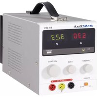
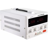
Operating instructions
Digital Multimeter BT-11
Item no. 1599499
Intended use
- Measuring and displaying electric parameters in the range of excess voltage category III (up to max. 250 V against ground potential, pursuant to EN 61010-1) or lower
- Measuring direct and alternating voltage up to a maximum of 250 V
- Measurement of direct current up to max. 200mA
Also designed to measure resistance values of up to 2000 kOhm - Diode test
- Battery test for 9 and 1.5V batteries under load condition
- Rectangular signal generator
Operation is only permissible using the stated battery type (2 x LR44 or identical).
The measuring instrument must not be operated when it is open, i.e. with an open battery or fuse compartment. Measuring in damp rooms or under unfavourable ambient conditions is not admissible.
Unfavourable ambient conditions are:
- Wetness or high air humidity
- Dust and flammable gases, vapours or solvent,
- Thunderstorms or similar conditions such as strong electrostatic fields etc!
The multimeter (referred to as DMM in the following) indicates measured values on the digital display. The measuring value display of the DMM comprises 2000 counts (count = smallest display value).
The individual measuring ranges are selected via a rotary switch.
The measuring circuit is protected against overload with a fine-wire fuse. The fuse is located in the red test prod.
For safety reasons, the measuring cables are permanently connected to the measuring device and cannot be changed.
The measuring device can be used for do-it-yourself or for professional applications.
For safety and approval purposes, you must not rebuild and/or modify this product. If you use the product for purposes other than those described above, the product may be damaged. In addition, improper use can cause hazards such as short circuiting, fire, electric shock etc. Read the instructions carefully and keep them. Make this product available to third parties only together with its operating instructions.
This product complies with the statutory national and European requirements. All company names and product names are trademarks of their respective owners. All rights reserved.
Explanations of symbols and units on the multimeter
| V Alternating voltage | |
| V Direct voltage | |
| V Volt (unit of electric potential) | |
| mV Millivolt (exp.-3) | |
| mA Milliampere (unit of electric current, exp.-3) | |
| μA Microampere (exp.-6) | |
| Ω Ohm (unit of electric resistance) | |
| kΩ Kilo Ohm (exp.3) | |
| ← | Diode test |
| → | Battery test |
| π Rectangular signal generator | |
| CAT III Over-voltage category 3 | |
Delivery content
- Multimeter with permanently attached measuring leads
- 2 LR44 batteries (or identical batteries)
- Operating instructions

Latest operating instructions
Download the latest operating instructions via the link www.conrad.com/downloads or scan the QR code shown. Follow the instructions on the website.
Explanation of symbols

The lightning symbol inside a triangle is used when there is a potential risk of personal injury, such as electric shock.

An exclamation mark in a triangle indicates important instructions in this operating manual that absolutely have to be observed.

The arrow symbol indicates specific tips and advice on operation.

This product has been CE-tested and meets the necessary European guidelines.
Covar-voltage category III for measuring building wiring installation (e.g. outlets or sub-distributions). This category also covers all smaller categories (e.g. CAT II for measuring electronic devices).

potential
Safety instructions

Read the operating instructions carefully and especially observe the safety information. If you do not follow the safety instructions and information on proper handling in this manual, we assume no liability for any resulting personal injury or damage to property. Such cases will invalidate the warranty/ guarantee.

a) General
The device is not a toy. Keep it out of the reach of children and pets.
- Do not leave packaging material lying around carelessly. This may become dangerous playing material for children.
- Protect the product from extreme temperatures, direct sunlight, strong jolts, high humidity, moisture, flammable gases, vapours and solvents.
- Do not place the product under any mechanical stress.
- If it is no longer possible to operate the product safely, take it out of operation and protect it from any accidental use. Safe operation can no longer be guaranteed if the product:
- is visibly damaged,
- is no longer working properly,
- has been stored for extended periods in poor ambient conditions or
-
has been subjected to any serious transport-related stresses.
-
Please handle the product carefully. Jolts, impacts or a fall even from a low height can damage the product.
- In commercial and industrial facilities the regulations for the prevention of accidents as laid down by the professional trade association for electrical equipment and devices need to be observed.
- In schools, training centres, computer and self-help workshops, handling of measuring instruments must be supervised by trained personnel in a responsible manner.
- Before measuring voltages, always make sure that the measuring instrument is not set to a measuring range for currents. The voltage between the measuring instrument and earth must never exceed 250 V DC/AC in CAT III.
- The test prods have to be removed from the measured object every time the measuring range is changed.
- Take particular care when dealing with voltages exceeding 25 V AC or 35 V DC! Even at these voltages it is possible to get a fatal electric shock if you touch electric conductors.
- Check the measuring device and its measuring lines for damage before each measurement. Never carry out any measurements if the protecting insulation is defect (torn, ripped off etc.)
- To avoid an electric shock, make sure not to touch the connections/measuring points to be measured neither directly nor indirectly during measurement. When during measuring, do not grip beyond the grip range markings present on the test prods. Do not use the multimeter immediately before, during or after thunder and lightning (thunderstrike / high-energy over-volts!). Please make sure that your hands, your shoes, your clothing, the floor, switches and switching components are dry.
-
Avoid an operation near:
-
strong magnetic or electromagnetic fields
-
transmitter aerials or HF generators
This may falsify the measuring value.
- Do not switch the measuring instrument on immediately after it has been taken from a cold to a warm environment. Condensation water that forms might destroy your device. Leave the device switched off and wait until it has reached room temperature.
- Consult an expert when in doubt about operation, safety or connection of the device.
- Maintenance, modifications and repairs are to be performed exclusively by an expert or at a qualified shop.
- If you have questions which remain unanswered by these operating instructions, contact our technical support service or other technical personnel.
b) (Rechargeable) batteries
- Correct polarity must be observed while inserting the (rechargeable) batteries.
- (Rechargeable) batteries should be removed from the device if it is not used for a long period of time to avoid damage through leaking. Leaking or damaged (rechargeable) batteries might cause acid burns when in contact with skin, therefore use suitable protective gloves to handle corrupted (rechargeable) batteries.
- (Rechargeable) batteries must be kept out of reach of children. Do not leave (rechargeable) batteries lying around, as there is risk, that children or pets swallow them.
- All (rechargeable) batteries should be replaced at the same time. Mixing old and new (rechargeable) batteries in the device can lead to (rechargeable) battery leakage and device damage.
- (Rechargeable) batteries must not be dismantled, short-circuited or thrown into fire. Never recharge non-rechargeable batteries. There is a risk of explosion!
Initial operation
The batteries are already inserted in the DMM upon delivery.
Rotary switch
The individual measuring functions can be set via the rotary switch. If the rotary switch is set to "OFF", the measuring device is switched off. Always turn the measuring device off when it is not in use.
Measuring

exceed the maximum permitted input values. Do not contact circuits or parts
of circuits if there could be voltages higher than 25 V ACrms or 35 V DC present within them. Mortal danger! Before measuring, check the connected measuring cable for damage such as, for example, cuts, cracks or squeezing. Defective measuring cables must no longer be used. Mortal danger!
a) Voltage measuring "V"
Proceed as follows to measure DC voltages (V #):
- Turn the DMM on on the rotary switch and select the right measuring range for your voltage "V"
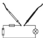
- Now connect the two test prods to the object to be measured (battery, circuit etc.). The red measuring tip indicates the positive pole, the black measuring tip the neg
- The polarity of the respective measuring value is indicated on the together with the current measuring value.
As seen as a minus "-" appears for the direct voltage in front of the measuring value, the measured voltage is negative (or the measuring tips have been mixed up).
After you finish testing, always switch the measuring device off. Turn the rotary switch to "OFF".
Proceed as follows to measure AC voltages (V T):
- Turn the DMM on on the rotary switch and select the right measuring range for your voltage "V".
- Now connect the two measuring prods to the object to be measured (generator, switching etc.).
The measuring value is indicated on the display
The voltage range "V DC/AC" shows an input resistance of >1 MOhm.
After you finish testing, always switch the measuring device off. Turn the rotary switch to "OFF".
b) Resistance measuring

sure that all the circuit parts, switches and components and other objects of measurement are disconnected from the voltage at all times.
Proceed as follows to measure the resistance:
- Turn the DMM on on the rotary switch and select the right measuring range for your voltage "Ω".
- Check the measuring leads for continuity by connecting both measuring prods to one another. After that the resistance value must be approximately 3 Ohm.
- Now connect the measuring prods to the object to be measured. As long as the object to be measured is not high-resistive or interrupted, the measured value will be indicated on the display.
- As soon as "1" (= overflow) appears on the display, you have exceeded the measuring range or the measuring circuit has been interrupted. Switch to the next higher measuring range.
- After you finish testing, always switch the measuring device off. Turn the rotary switch to "OFF".

carry out a resistance measurement, make sure that the measuring points which you contact with the test prods are free from dirt, oil, solderable lacquer or the like. An incorrect measurement may result under such circumstances.
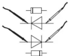
c) Diode test

measure that all the circuit parts, switches and components and other objects of the measurement are disconnected from the voltage at all times.
Select the measuring range
- Check the measuring leads for continuity by connecting both measuring prods to one another.
After that the value must be approx. 003. - Now connect the two measuring prods with the object to be measured (diode).
- The display shows the continuity voltage in Millivolt (mV). Usual voltage values: silicon diode ca. 700 mV, germanium diode ca. 250 mV. If "1" is indicated, the diode is measured in reverse direction or the diode is faulty (interruption).
- After you finish testing, always switch the measuring device off. Turn the rotary switch to "OFF".
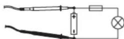
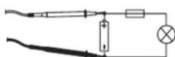
d) Battery test
With the two measuring ranges, you can test all batteries and accumulators with a nominal voltage of 9V / 1.5V or 1.2V . The cells are slightly charged during testing, which corresponds to actual operation.
Select the respective measuring range
For 1.2V accumulators, select the 1.5V range.
- Connect the red measuring tip with the positive pole and the black measuring tip with the negative pole.
- The contact voltage of the battery/accumulator is indicated on the display.

new batteries or completely charged accumulators, the contact voltage is slightly higher than the stated nominal voltage.
- After you finish testing, always switch the measuring device off. Turn the rotary switch to "OFF".
e) Rectangular signal generator
In this range, the DMM works as a rectangular generator for testing audio switching or similar. In this measuring range, the measuring tips carry a signal of 60 ± 10 Hertz and an amplitude of 3 Vpp.
Do not short-circuit the measuring cables in this measuring range.
Select the measuring range.
- Connect the two measuring tips with the measuring object (red = signal, black = reference mass).
- After you finish testing, always switch the measuring device off. Turn the rotary switch to "OFF".
f) Direct current measuring A ---
Current measuring is possible in three ranges from 0 to 200mA . All current measuring ranges are provided with fuses and thus protected against overload.
Proceed as follows to measure DC voltages:
- If you want to measure currents up to max. 2000 A , set the rotary switch to the position "2000 A " or the matching measuring range.
- Now connect the two test prods in series with the object to be measured (battery, circuit etc.); the display indicates the polarity together with the currently measured value.
Never measure currents above 200mA in the A / mA range, since this would cause the fuse to trip. The voltage in the measuring circuit may not exceed 250 V. In current measuring range the two test prods have a low-impedance connection. Merely touching a metal end poses the risk of an electric shock.
If measuring is no longer possible (measuring value does not change, etc.), the internal fuse may have been triggered. See the next chapter to read about replacing the fuse.
- After you finish testing, always switch the measuring device off. Turn the rotary switch to "OFF".
Care and cleaning
Live components may be exposed if the covering is opened or components are removed. The connected lines must be disconnected from all measuring objects prior to cleaning or repairing the device.
- Disconnect the product from the power supply before cleaning.
- Do not use scrubbing agents or chemical agents containing petrol, alcohol or the like to clean the product. These could corrode the surface of the measuring instrument. The fumes are furthermore a health hazard and are explosive. Moreover, you should not use sharp-edged tools, screwdrivers or metal brushes or similar for cleaning.
- To clean the device, the display or measurement lines, use a clean, dry lint-free anti-static cleaning cloth.
- Do not immerse the product in water.
Replacing the fuse
If no measurement data is shown on the display, the fuse is probably defective. The fuse is integrated in the red test prod in a user-friendly position. To replace the fuse, proceed as follows:
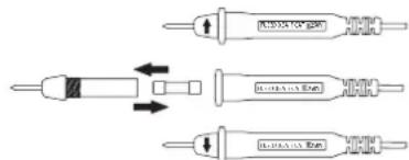
- Turn off the measuring instrument and remove both test prods from the device under test.
- Unscrew the front end of the red test prod from the reaching area of the hands.
- Replace the defective fuse with a fuse of the same type and nominal current (quick-acting 0.5A / 250V fine-wire fuse).
- Carefully screw the red test prod back together.
Inserting/changing the batteries
Operation of the measuring device requires two button cell batteries (LR44 or identical). A battery replacement is required when the display becomes weaker.
To insert/replace the battery, proceed as follows:
- Disconnect the measuring device from the measuring circuit and turn it off.
- Loosen the casing screw on the rear and open the casing.
- Place new batteries into the battery compartment observing the correct polarity. Always observe the indicated polarity.
- Now, close the cover carefully again.
Never operate the measurement device when it is open. RISK OF FATAL INJURY! Do not leave flat batteries in the device. Even batteries protected against leaking can corrode and thus release chemicals which may be detrimental to your health or destroy the battery compartment.
Suitable replacement batteries are available under order number 652044 (order 1 set of 2).
Troubleshooting
In purchasing the DMM, you have acquired a product which has been designed to the state of the art and is operationally reliable. Nevertheless, problems or faults may occur. For this reason, the following is a description of how you can eliminate possible malfunctions yourself.
| Error | Possible cause |
| The multimeter does not function. | Are the batteries spent? Check the status. |
| No measuring value change. | Is the wrong measuring function active? The internal overload fuse is defective. |
Disposal
a) Product

Electronic devices are recyclable waste and must not be disposed of in the household waste. At the end of its service life, dispose of the product according to the relevant statutory regulations.
ave any inserted (rechargeable) batteries and dispose of them separately from the product.
b) (Rechargeable) batteries
As the end user, you are required by law (Battery Ordinance) to return all used (rechargeable) batteries; disposal of them in the household waste is prohibited!

rated (rechargeable) batteries are labelled with this symbol to indicate that disposal in the domestic waste is forbidden. The designations for the heavy metals involved are: Cd = Cadmium, Hg = Mercury, Pb = Lead (name on (rechargeable) batteries, e.g. below the trash icon on the left).
Used (rechargeable) batteries can be returned to collection points in your municipality, our stores or wherever (rechargeable) batteries are sold.
You thus fulfil your statutory obligations and contribute to the protection of the environment.
Technical data
Display. 2000 counts
Measuring frequency. 2.5 measurements per sec
Input resistance. >1 MΩ
Operating voltage 3 V/DC (2 x LR 44 or identical)
Ambient conditions. Operation: 0 to +40^ , max. 80% RH (non-condensing)
Dimensions (W x H x D) 52 x 27 x 103 (mm)
Weight ca. 80 g
a) Measurement tolerances
Statement of accuracy in ± [% of reading + display error in counts (= number of smallest points)]. The accuracy is valid for one year at a temperature of +23^ ± 5^ , and at a relative humidity of less than 75% , non-condensing. The warming-up time is about 1 minute.
| AccuracyMeasuring rangeType of operat | |
| Direct voltage | ±(1.5% + 2 counts)200 mV |
| ±(2.5% + 2 counts)2000 mV - 250 V | |
| ±(2.5% + 9 counts)200 - 250 VAternatin | |
| ±(2.5% + 9 counts)2000 μA - 200 mADir | |
| ±(2.5% + 5 Counts + 3 Ohm)200 Ohm - |
Diode test. Test voltage: 1.3V / test current 0.9mA
Battery test. 50 mA load current in 1.5 V range
5 mA load current in 9 V range
b) Max. input sizes/overload protection
Voltage measurement. 250 V/DC or V/ACrms (rms = effective)
Current measurement. max. 200 mA DC, max. 250 VDC
Overload protection.. Fine fuse 5× 20mm (F500mA/250V)
Quick-acting 500 mA, 250 V. May only be exchanged by an expert.

exceed the maximum permitted input values. Do not touch any circuits or parts of circuits, if they can have higher voltages than 25 V Acrms or 35 V/DC. Mortality is danger!

by check the technical safety of the device and the measuring cables, e.g. for damage to the casing etc. Do not use the measuring device in case of damage!
The measuring range diodes and the battery test, rectangular signal generator as well as resistance measuring are not protected against excess input voltage or overload. Exceeding the max. admissible input values or overload may damage the measuring device or lead to mortal danger!
This is a publication by Conrad Electronic SE, Klaus-Conrad-Str. 1, D-92240 Hirschau (www.conrad.com).
All rights including translation reserved. Reproduction by any method, e.g. photocopy, microfiling, or the capture in electronic data processing systems require the prior written approval by the editor. Reprinting, also in part, is prohibited. This publication represents the technical status at the time of printing.
Copyright 2017 by Conrad Electronic SE.
1599499_V2_1117_02_jc_m_en
Mode d'emploi
Digital Multimeter BT-11
N^o de commande:1599499
Utilisation prévue
Dimensions (L x H x P) 52 x 27 x 103 (mm)
Poids....env.80g
Display. 2000 counts
Meetinterval 2,5 metingen per seconde
Stroommeting. max. 200 mA DC, max. 250 V DC
Bescherming gegen overbelasting.... Fijnzekering 5 x 20 mm (F500mA/250V)
Copyright 2017 by Conrad Electronic SE. 1599499_V2_1117_02_jc_m.nl