
Cube - Thermostat Atag - Free user manual and instructions
Find the device manual for free Cube Atag in PDF.
| Product type | Room thermostat |
| Brand | Atag |
| Model | Cube |
| Dimensions (W x H x D) | 93 x 88 x 24 mm |
| Power supply | BUS 8-24V max, 6 mA |
| Operating temperature | 0 to 40°C |
| Storage temperature | -10 to 70°C |
| Protection rating | IP30 (proper installation) |
| Insulation class | III |
| Sensor accuracy | 1% |
| Display | Backlit screen (room temperature, modes, Wi-Fi detected) |
| Main functions | Heating, cooling, manual mode, program mode, frost protection, timed adjustment |
| Number of zones | Zone assignment via menu (NR02) |
| Connection | Shielded cable or 2-wire phone cable, max 50 m, min 0.6 mm² |
| Installation | Wall-mounted, 1.5 m above floor, away from heat sources |
| Maintenance and cleaning | Clean with a dry cloth, no solvents or harsh chemicals |
| Safety | Use by children aged 8 and over under supervision, do not climb, disconnect before installation |
| Adjustable settings | Temperature correction (CF01), backlight (CF11, CF12) |
| Possible errors | Zone assignment error, damaged sensor (---Err) |
| Compliance | Directive 2014/53/EU, recycling according to WEEE |
Frequently Asked Questions - Cube Atag
User questions about Cube Atag
0 question about this device. Answer the ones you know or ask your own.
Ask a new question about this device
Download the instructions for your Thermostat in PDF format for free! Find your manual Cube - Atag and take your electronic device back in hand. On this page are published all the documents necessary for the use of your device. Cube by Atag.
USER MANUAL Cube Atag
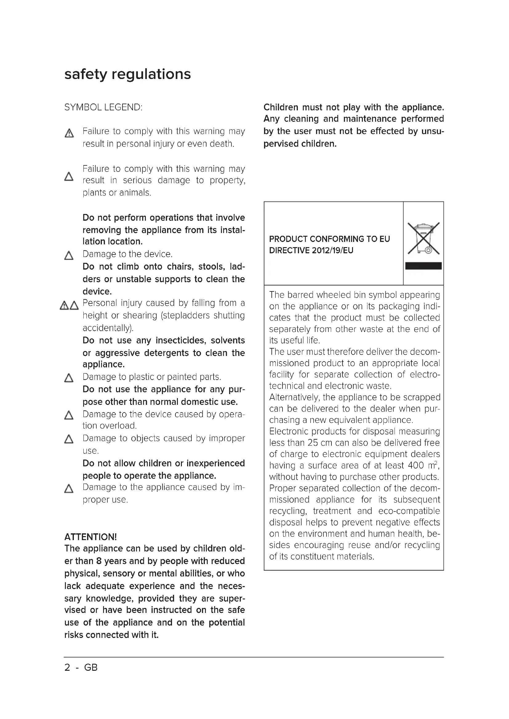
Failure to comply with this warning may result in personal injury or even death.
Failure to comply with this warning may result in serious damage to property, plants or animals.
Do not perform operations that involve removing the appliance from its installation location.
Damage to the device. Do not climb onto chairs, stools, ladders or unstable supports to clean the device.
Personal injury caused by falling from a height or shearing (stepladders shutting accidentally). Do not use any insecticides, solvents or aggressive detergents to clean the appliance.
Damage to plastic or painted parts. Do not use the appliance for any purpose other than normal domestic use.
Damage to the device caused by operation overload.
Damage to objects caused by improper use. Do not allow children or inexperienced people to operate the appliance.
Damage to the appliance caused by improper use.
ATTENTION!
The appliance can be used by children older than 8 years and by people with reduced physical, sensory or mental abilities, or who lack adequate experience and the necessary knowledge, provided they are supervised or have been instructed on the safe use of the appliance and on the potential risks connected with it.
Children must not play with the appliance. Any cleaning and maintenance performed by the user must not be effected by unsupervised children.
PRODUCT CONFORMING TO EU DIRECTIVE 2012/19/EU
The barred wheeled bin symbol appearing on the appliance or on its packaging indicates that the product must be collected separately from other waste at the end of its useful life.
The user must therefore deliver the decommissioned product to an appropriate local facility for separate collection of electrotechnical and electronic waste.
Alternatively, the appliance to be scrapped can be delivered to the dealer when purchasing a new equivalent appliance.
Electronic products for disposal measuring less than 25cm can also be delivered free of charge to electronic equipment dealers having a surface area of at least 400m^2 without having to purchase other products. Proper separated collection of the decommissioned appliance for its subsequent recycling, treatment and eco-compatible disposal helps to prevent negative effects on the environment and human health, besides encouraging reuse and/or recycling of its constituent materials.
technical features
| Technical data | |
| Power supply BUS 8 to 24V max / Limited Power | er Source = Complies |
| Electrical uptake | 6 mA |
| Operating temperature | 0 to 40°C |
| Storage temperature | -10 to 70°C |
| Dimensions | 93 x 88 x 24 mm |
| Bus wire length and cross-sectional area | max. 50 m - min. 0,6 mm² |
| NOTE: IN ORDER TO AVOID INTERFERENCE PROBLEMS, USE A SHIELDED CABLE OR TWISTED PAIR CABLE. | |
| Insulation class | III |
| Protection rating | IP30 (when installed as specified) |
| Temperature sensor | ±1% |
| Product Technical Sheet | |
| Supplier name ATAG | |
| Manufacturer's model ID | Cube |
| Temperature control class V | |
| Energy efficiency contribution (%) for space heating +3% | |
| If an Atag external sensor is added: | |
| Temperature control class VI | |
| Energy efficiency contribution (%) for space heating +4% | |
| In a system with 3 zones with 1 ATAG Oz and 1 ATAG Cube: | |
| Temperature control class VIII | |
| Energy efficiency contribution (%) for space heating +5% | |
technical features
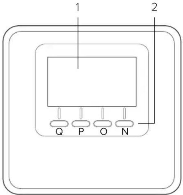
Room controller:
- display
- keys
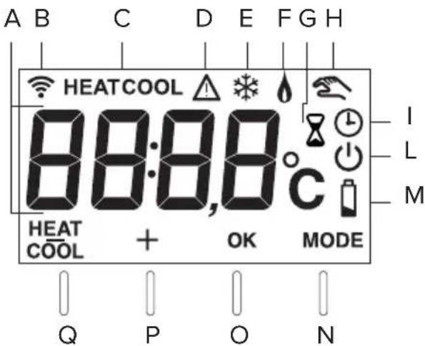
Display:
A. Detected room temperature
B. WiFi device detected on bus
C. Heating/cooling mode indication
D. Fault
E. Cooling/anti-freeze mode in controlled zone
F. Heat request
G. Timer-based modification of room temperature set-point in the schedule programming (when enabled)
H. Manual mode active
1. Programmed mode active (heating/cooling as scheduled on a device capable of setting schedule)
L. Controlled zone OFF
M. Battery low charge
N. Mode key ("MODE")
O. Confirm key (OK)
P. Increase temperature setting key (+)
Q. Decrease temperature setting key (-) Set mode to heating (HEAT) or cooling (COOL).
operating mode
The system's operating mode can be set to heating or cooling when the device is connected to a product which supports both modes (such as a heat pump).
Press the "MODE" key (Fig. 1) to display:
Press "MODE" again (Fig. 2) for 5 seconds.
HEAT COOL will display next to the key.
Now press the key to select the mode (Fig. 3)
The display will show:
-
"HEAT" heating
-
"COOL" cooling.
Press the OK button to confirm the selection.
NOTE:
The heating/cooling mode selection applies to the entire system.
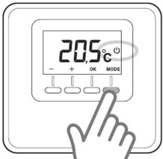
Fig.1
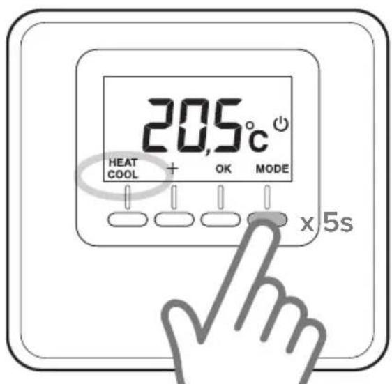
Fig. 2
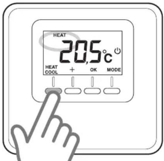
Fig. 3
manual operation
Manual operation heats or cools the zone in which the thermostat is installed, and maintains the manual temperature setting throughout the day (time scheduling is disabled).
Press the "MODE" button until the display shows " 一 (Fig. 4).
Modifying the room temperature
In manual mode, the set-point temperature (default value 20^ ) can be modified. Press the temperature adjustment keys "+" and "-" to set the room temperature (Fig. 5). Press "OK" to confirm.
The set value will flash on the display for a few seconds, after which the display will once again show the detected room temperature.
Disabling
heating/cooling
You can disable heating/cooling in the zone in which the thermostat is installed. Press the "MODE" button until the display shows:
When heating is off, the anti-freeze function is enabled.
Anti-freeze function
When the anti-freeze function is enabled, the display shows:
In this mode, central heating will only activate if the room temperature falls below 5^ , to protect the pipes against freezing up.
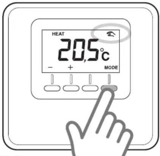
Fig. 4
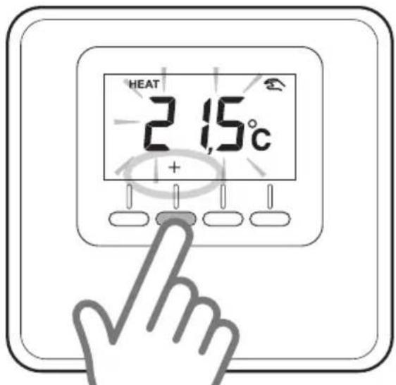
Fig. 5
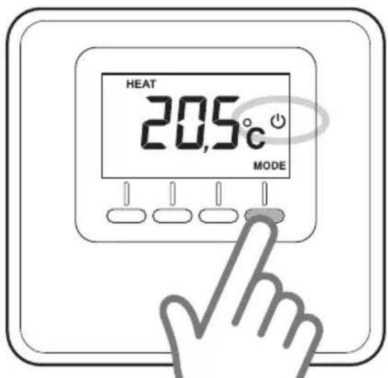
Fig. 6
programmed operation
Programmed operation is controlled by the heating/cooling schedule set on a device capable of setting schedules.
Press the "MODE" button until the display shows "Fig. 7).
Timed adjustment room temperature
In programmed mode, you can temporarily modify the set-point temperature set on a device capable of setting schedule.
Press the temperature adjustment keys "+" and "- to set the room temperature (Fig. 8).
Press "OK" to confirm the temporary setting.
The display will now show " 空 " and the time for which the changed setting applies will flash (3h default) (Fig. 9).
Press "+" and "- to set the duration of the modification, which can vary between 0 hour (minimum) and 24 hours (maximum). Press "OK" to confirm the modified setting.
The display will now show the detected room temperature again.
When the temporary setting times out, the display will again show the set-point temperature set with a device capable of setting schedule.
To cancel the modified setting, press "MODE" and select manual mode.
Press the "MODE" button until the display shows " 品 to return to programmed operation.

Fig. 7
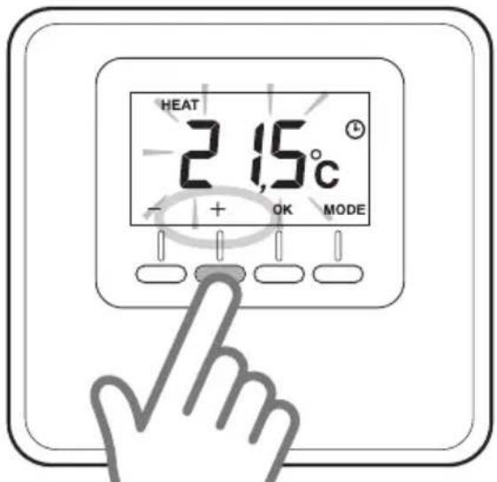
Fig. 8
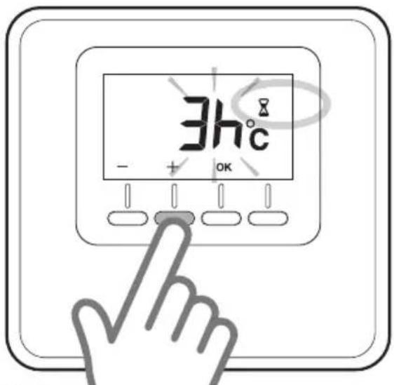
Fig. 9
installing
Positioning
The device detects the room temperature, therefore several factors should be taken into account when choosing an installation site. Position the device far from heat sources (radiators, sunlight, fireplaces, etc.) and from draughts, doorways and windows which could affect the temperature readings. It should be installed approximately 1.5 metres above the floor level.

ATTENTION!
Installation should be performed by a qualified technician. Before making any connections, shut off electrical power to the heat generator with its external two-position switch. Power supply of the device must be connected to a circuit breaker.
Wall installation
- If necessary, install the mounting plate to the electrical box included in the kit (Fig. 10).
- Detach the thermostat's base by pressing down the tab at the bottom (Fig. 11).
Fix the base to the wall at the chosen position, using the plugs and screws supplied with the kit (Fig. 12).
Electrical connection to the heat generator.
IN ORDER TO AVOID INTERFERENCE PROBLEMS, USE A SHIELDED CABLE OR TWISTED PAIR CABLE.
- Route the wires through the slot and connect them to terminals B and T.
- Once the wires have been connected, restore the thermostat by first inserting the top and then rotating it downwards while pressing it gently in towards the wall.
- Connect the thermostat wire to the BUS terminal on the heat generator's terminal board (Fig. 13).
- Power up the heat generator
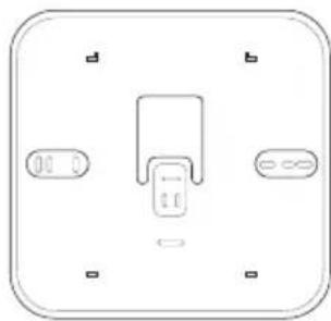
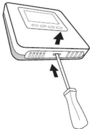
Fig. 10
Fig. 11
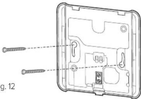
Fig. 12
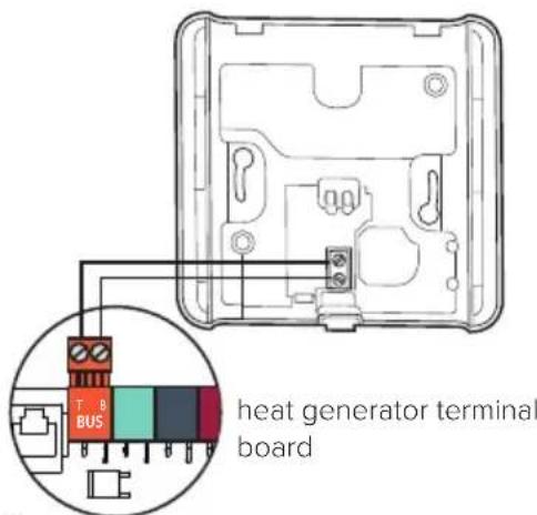
Fig. 13
installing
Associating the zone
- Check that the thermostat is powered up and properly hooked up
- Hold the "+" key on the thermostat down for 5 seconds (Fig. 14).
The display will alternate between the software version and modification index.
- Hold the "+" key on the thermostat down for 5 seconds.
The display will show the parameter "nr02" (Fig. 15). - Press "OK" to enter the zone association menu; the display will show the first available zone.
- Press "+" and "-" to select the zone you wish to associate (Fig. 16).
- Press 'OK' to confirm.
- Press "MODE" to return to the main screen.
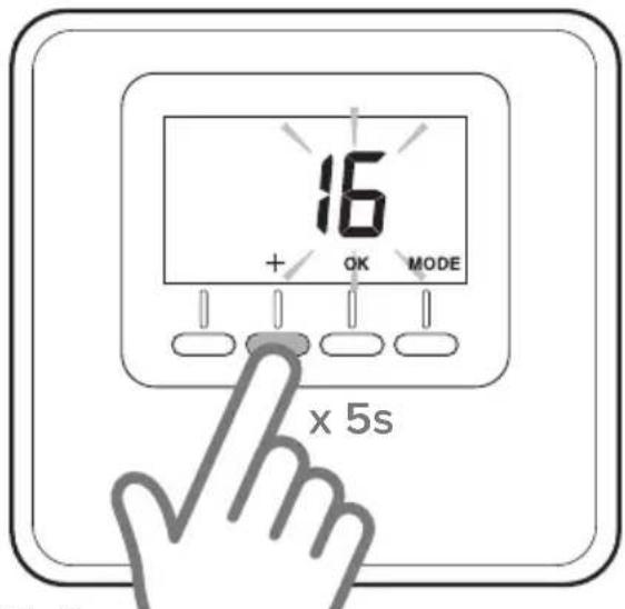
Fig.14
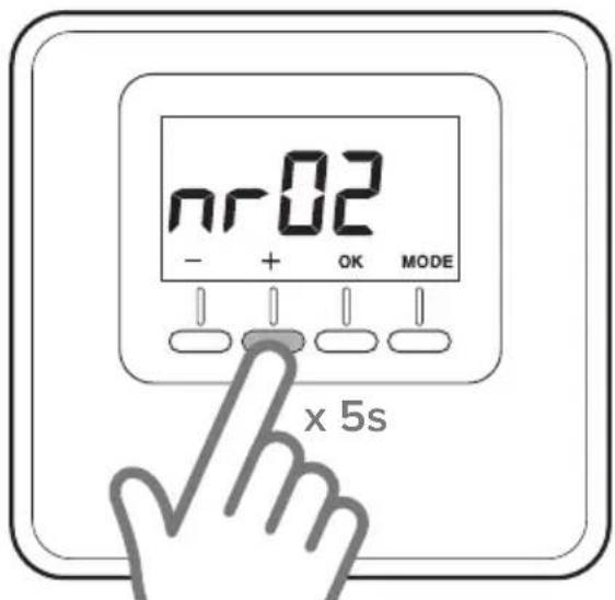
Fig.15
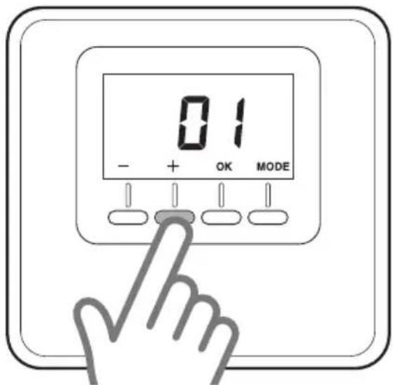
Fig.16
technical adjustments
TABLE OF PARAMETERS
| ATAG Cube | ||
| - Hold "+" down for 5 seconds. The display will alternate between the software version and modification index. - Press "OK" to enter the settings menu. - Press "+" and "-" to scroll through the parameters. - Press "OK" button to select a parameter. | ||
| Par. Description Default | ||
| CF01 Room temperature correction (range +/-5°C) 0°C | ||
| CF11 | 0: Display OFF after 10s1: Display always on | 1 |
| CF12 | 0: Backlight off1: Backlight OFF after 5s of inactivity | 1 |
TABLE OF ERRORS
| Error Cause Solution | ||
| Err - Ebus | Zone association error: the zone associated with the device is already assigned | Check the installed thermostats. Assign a different zone. |
| --- Err | The thermostat is damaged Replace it | |
veiligheidsnormen
LEGENDE VAN DE SYMBOLEN
OBJECT: EC Declaration of Conformity
Hereby, Ariston Thermo S.p.A. (viale A.Merloni 45, 60044-Fabriano (AN), ITALY) declares that this product is in compliance with the essential requirements and other relevant provisions of Directive RED 2014/53/EU
The complete EU Declaration of Conformity can be found at: http://www.aristonthermo.com/en/download-area
ATAG Heating Technology Ltd.
Sales department
47 Castle Street - Reading, Berkshire RG1 7SR

- ATTENTION!
- technical features
- Room controller:
- Display:
- operating mode
- NOTE:
- manual operation
- Modifying the room temperature
- Disabling
- heating/cooling
- Anti-freeze function
- programmed operation
- Timed adjustment room temperature
- installing
- Positioning
- Wall installation
- Electrical connection to the heat generator.
- IN ORDER TO AVOID INTERFERENCE PROBLEMS, USE A SHIELDED CABLE OR TWISTED PAIR CABLE.
- Associating the zone
- technical adjustments
- veiligheidsnormen
- LEGENDE VAN DE SYMBOLEN
- OBJECT: EC Declaration of Conformity
- ATAG Heating Technology Ltd.
Brand : Atag
Model : Cube
Category : Thermostat