
BrainZ - Thermostat Atag - Free user manual and instructions
Find the device manual for free BrainZ Atag in PDF.


| Product Type | Programmable Thermostat |
| Brand | Atag |
| Model | BrainZ |
| Dimensions (W x H x D) | 80 x 80 x 30 mm |
| Weight | 100 g |
| Power Supply | Mains (230V AC) or 2x AA batteries |
| Display | Touchscreen LCD |
| Connectivity | Wi-Fi (2.4 GHz) |
| Compatibility | Gas, oil, electric, heat pump systems |
| Programming | 7-day, 4 periods per day |
| Smart Features | Geofencing, adaptive learning, voice assistant support |
| Temperature Range | 5°C to 35°C |
| Accuracy | ±0.5°C |
| Child Lock | Yes |
| Energy Saving Mode | Away, vacation, economy |
| Maintenance | Clean with a soft, dry cloth |
| Spare Parts Available | Battery compartment cover, wall base |
| Warranty | 2 years |
Frequently Asked Questions - BrainZ Atag
User questions about BrainZ Atag
0 question about this device. Answer the ones you know or ask your own.
Ask a new question about this device
Download the instructions for your Thermostat in PDF format for free! Find your manual BrainZ - Atag and take your electronic device back in hand. On this page are published all the documents necessary for the use of your device. BrainZ by Atag.
USER MANUAL BrainZ Atag
Operating Instructions
Room control unit RSC and RSC-OT
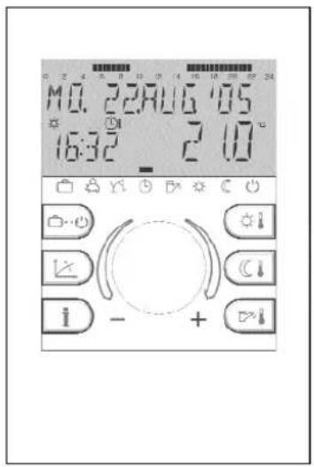
Table of contents
USER LEVEL
Operating instruments 4
Operation start-up - language selection - device identification - standard display ....5-6
Temperature settings required daytime temperature, required reduced temperature, required hot water temperature ....7
Operational mode selection for heating and hot water (summary) 8
Function of operational modes holiday, absence, party, automatic, summer, permanent heating, permanent reduced heating, standby ....9
Quick operational mode selection (automatic, party, absence, hot-water reloading) 10
Heating characteristics (heating curve) 17
Plant information 12-133
PROGRAMMING LEVEL
LEVEL SUMMARY schematic block diagram 14-15
Level TIME PROGRAMS Programming, copying, reloading of standard programs, table for individual programs .....16-22
Level TIME-DATE Time, calender year, calender month, calender day, automatic summer-/wintertime reset .....23
Level SYSTEM Language selection, clearing of time programs, control mode, summer switching-off .....22-26
Level DOMESTIC HOT WATER Economic temperature, legionella protection 27
Level UNMIXED CIRCUIT Reduced mode, heating system .....28-29
Alarm messages ....30
Notes 37
Technical specification 32
General operation
Operating instruments

Operation
Symbolism used in this manual:

Turn: select parameters, change values

Press once: confirm, store

Display test
Language selection
Country code
The center-positioned rotary-push button and the labeled keys guarantee a simple and easy operation. It is however recommended to read this manual attentively to be informed about the repeating steps.
– Each value in the display appears flashing and can be modified with the rotary-push button. A flashing display is appropriately marked in this manual.
Turn to the right (+): Increase values
Turn to the left (-): Decrease values
- Press once: Acceptance of the selected and indicated value, store.
- Keep pressed: Entry into the programming level (level selection),
The last operation step will be stored automatically after approx. 60 seconds if it was not stored by means of the rotary-push button.
Start-up
In case of initiation of the plant or after every power failure a display test of the large display is carried out with automatic error diagnosis. At that all available segments and symbols will be displayed.
Language selection
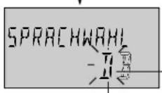
In case of first initiation the desired language can be chosen after the display test. The languages DE, GB, FR, IT, NL, ES, PT, HU, CZ, PL, RO, RU, TR, S, N can be selected.
Note: This display appears after every restart on day of first initiation until midnight. After that the language can only be changed in the level SYSTEM - parameter LANGUAGE.

Device identification
After the display test and/or the language selection the device identification momentary appears with device type, interface and the corresponding number of software version.
Basic display
Provided that there is not any error message, the basic display indicates the date, time, heating mode ( ※ = daytime temperature, = reduced set back temperature) as well as the current boiler temperature or, if released, the room temperature. Response time program. The cursor below (■) indicates the current operating mode (see function of operating modes). The upper time bar shows the heating periods and the corresponding operating times of the current weekday.
An activated summer switch-off is represented in the basic display by a sunshade symbol ( ). The heating mode symbols ✝ or will be suppressed during an activated summer switch-off.
With acting frost protection function an ice crystal symbol appears in the basic display ( * ).
Temperature settings


This button is used to set the required daytime room temperature
This button is used to set the required set back room temperature
This button is used to set the required domestic hot water temperature
Adjustment (standard display mode only):
After pressing the button for the required temperature the current value appears flashing and can be adjusted directly with the rotary pushbutton.
Re-entry into the standard display is done by pressing the rotary-push button or the corresponding temperature button or automatically after approx. 60 seconds.
Operational mode selection for heating and hot water

With this button the required operational mode is selected. It appears in plaintext on the display, simultaneously a cursor at the lower edge of the display points to the appertaining program symbol.
Select: Pressing the button ☐ the previously selected operational mode appears flashing. The other operational modes can be selected and activated with the rotary-push button according to the following scheme.

flowchart
graph TD
    A["Entry into the previously selected heating operation mode"] --> B["Select required operational mode"]
    B --> C["accept, activate"]
    C --> D["set date or time"]
    D --> E["activate, re-entry to standard display"]

    subgraph Before
        F["HOLIDAY TILL 27:08"] --> G["ABSENT TILL 19:45"] --> H["PARTY TILL 02:30"]
    end

    subgraph After
        I["HOLIDAY TILL 15:30 27:08"] --> J["ABSENT TILL 15:30 19:45"] --> K["PARTY TILL 15:30 02:30"]
    end

    style Before fill:#f9f,stroke:#333
    style After fill:#bbf,stroke:#333
Functions of operational modes
| Plant off during holiday | Interrupt heating operation | Extend heating operation | Heating operation via timer | Domestic hot water only | Permanent heating operation | Permanent red. heating operation | Plant off frost protection |
| HOLI JAY TIL19:27 24.09 | ABSENT TIL10:27 19.30 | PARTY TIL19:27 02.27 | MO. 22.AUG. '0519:27 56.5 | SUMMER10:27 24.0 | HEATING19:27 72.0 | RED HEATING19:27 45.0 | STANJBY19:27 19.0 |
| Setting range:Actual date...actual date + 250 daysReturn to the previously selected operational mode at 0.00 o'clock of the set return date.Hot water operation is set to frost protection temperature of 5 °C.Earlier termination:Press button ,select required operational mode with rotary-push button and press again to activate. | Setting rangeP1:Heating operation is interrupted until next switching-on time of current operating time program (see level TIME PROGRAMS)0.5 ...24h:Heating operation is interrupted until set time of return.Earlier termination:Press button ,select required operational mode with rotary-push button and press again to activate. | Setting range:P1:Heating operation is continued until next switching-on time of current operating time program (see level TIME PROGRAMS)0.5 ...24h:Heating operation is continued until end of party.Earlier termination:Press button ,select required operational mode with rotary-push button and press again to activate. | Operating times:(see level TIME PROGRAMS)Heating and domestic hot water operation automatically according to settings of temperature values (see Temperature settings) and selected operating times program.Programming of individual operating times see level TIME PROGRAMS). | Operating times:(see level TIME PROGRAMS)Only hot water operation according to settings of hot water temperature (see Temperature settings) and selected operating times program.The heating operation is interrupted and frost protected.Programming of individual operating times see level TIME PROGRAMS). | Permanent heating and reduced hot water operation round the clock according to the settings of daytime room temperature and domestic hot water temperature (see Temperature settings) | Permanent reduced heating and reduced hot water operation round the clock according to the settings of set back temperature (see Temperature settings), reduced heating mode (see level UNMIXED CIRCUIT) and hot water economic temperature (see level DHW). | Heating and hot water plant completely switched off except for frost protection mode. |
Quick operational mode selection

flowchart
graph TD
    A["3 sec"] --> B["Automatic mode"]
    B --> C["Modify: if required"]
    C --> D["activate"]

    E["3 sec 3 sec3 sec"] --> F["Party mode Absence mode Manual hot water loading"]
    F --> G["1 TIME JHW"]
    G --> H["Setting range: 0...240 min\nFactory preset: 0.0 min"]
Short-time operational modes
Frequently used operating modes such as PARTY or ABSENT or reloading the hot water tank during set back mode can be selected quickly according to the left scheme.
Direct automatic mode
Pressing button for approx. 3 seconds activates the automatic mode via timer inevitably. Functions and setting range see Operational mode selection for heating and hot water - Function of operational modes.
Manual hot water loading
To activate manual hot water loading outdoor of operation times the button [→] has to be pressed for about 3 seconds. This turns on hot water preparation at any time for a period which may be adjusted with the rotary pushbutton between 0 ...240 minutes. Pushing the rotary pushbutton activates loading. Afterwards the controller returns to program operation.
At adjustment 0.0 the loading is independent of any time period. The tank will be loaded up to the set DHW-temperature value once.
Setting the heating characteristics (heating curve)


Setting range: OFF (heating circuit eliminated) 0,20...3,50
Factory preset: 1,50
Store modification
Note: The heating slope should be modified only in small steps and left for a while until steady condition can be obtained. Changes to the slope should be made in intervals of 0.1 every 1 or 2 days.

This button regulates the heating characteristics of the heating circuit in relation to outdoor temperature.
The adjustment is dependent of the plant installation and shows the relation between outdoor temperature and heat generator (boiler) temperature.
The slope sets the change of the supply temperature, if the outdoor temperature changes for 1 K.
Diagram of heating curves

line
| Outdoor temp.(°C) | Heat generator temperature (°C) for 0.20 | Heat generator temperature (°C) for 0.50 | Heat generator temperature (°C) for 0.75 | Heat generator temperature (°C) for 1.00 | Heat generator temperature (°C) for 1.25 | Heat generator temperature (°C) for 1.50 (factory preset) | Heat generator temperature (°C) for 1.75 | Heat generator temperature (°C) for 2.00 | | ----------------- | ---------------------------------------- | ---------------------------------------- | ---------------------------------------- | ---------------------------------------- | ---------------------------------------- | ------------------------------------------------------ | -------------------------------------- | -------------------------------------- | | 20 | 20 | 20 | 20 | 20 | 20 | 20 | 20 | 20 | | 16 | 30 | 35 | 40 | 45 | 50 | 55 | 60 | 65 | | 12 | 40 | 50 | 60 | 70 | 80 | 90 | 100 | 110 | | 8 | 50 | 65 | 80 | 95 | 110 | 125 | 140 | 155 | | 4 | 60 | 80 | 100 | 125 | 145 | 165 | 185 | 205 | | 0 | 70 | 95 | 125 | 155 | 185 | 210 | 235 | 260 | | -8 | 80 | 110 | 150 | 185 | 220 | 245 | 275 | 310 | | -16 | 90 | 125 | 175 | 210 | 245 | 275 | 310 | 345 | | -20 | 100 | 140 | 200 | 235 | 275 | 310 | 345 | 380 |Re-entry into the standard display is done be pressing the button 📄 Logain or automatically after approx. 60 seconds.
Plant information
flowchart
graph TD
    A["Outdoor temperature 135°"] --> B["Outdoor temperature"]
    B --> C["Outdoor temperature"]
    C --> D["Outdoor temperature"]
    D --> E["Outdoor temperature"]
    E --> F["Outdoor temperature"]
    F --> G["Outdoor temperature"]
    G --> H["Outdoor temperature"]
    H --> I["Outdoor temperature"]
    I --> J["Outdoor temperature"]
    J --> K["Outdoor temperature"]
    K --> L["Outdoor temperature"]
    L --> M["Outdoor temperature"]
    M --> N["Outdoor temperature"]
    N --> O["Outdoor temperature"]
    O --> P["Outdoor temperature"]
    P --> Q["Outdoor temperature"]
    Q --> R["Outdoor temperature"]
    R --> S["Outdoor temperature"]
    S --> T["Outdoor temperature"]
    T --> U["Outdoor temperature"]
    U --> V["Outdoor temperature"]
    V --> W["Outdoor temperature"]
    W --> X["Outdoor temperature"]
    X --> Y["Outdoor temperature"]
    Y --> Z["Outdoor temperature"]
    Z --> AA["Outdoor temperature"]
    AA --> AB["Outdoor temperature"]
    AB --> AC["Outdoor temperature"]
    AC --> AD["Outdoor temperature"]
    AD --> AE["Outdoor temperature"]
    AE --> AF["Outdoor temperature"]
    AF --> AG["Outdoor temperature"]
    AG --> AH["Outdoor temperature"]
    AH --> AI["Outdoor temperature"]
    AI --> AJ["Outdoor temperature"]
    AJ --> AK["Outdoor temperature"]
    AK --> AL["Outdoor temperature"]
    AL --> AM["Outdoor temperature"]
    AM --> AN["Outdoor temperature"]
    AN --> AO["Outdoor temperature"]
    AO --> AP["Outdoor temperature"]
    AP --> AQ["Outdoor temperature"]
    AQ --> AR["Outdoor temperature"]
    AR --> AS["Outdoor temperature"]
    AS --> AT["Outdoor temperature"]
    AT --> AU["Outdoor temperature"]
    AU --> AV["Outdoor temperature"]
    AV --> AW["Outdoor temperature"]
    AW --> AX["Outdoor temperature"]
    AX --> AY["Outdoor temperature"]
    AY --> AZ["Outdoor temperature"]
    AZ --> BA["Outdoor temperature"]
    BA --> BB["Outdoor temperature"]
    BB --> BC["Outdoor temperature"]
    BC --> BD["Outdoor temperature"]
    BD --> BE["Outdoor temperature"]
    BE --> BF["Outdoor temperature"]
    BF --> BG["Outdoor temperature"]
    BG --> BH["Outdoor temperature"]
    BH --> BI["Outdoor temperature"]
    BI --> BJ["Outdoor temperature"]
    BJ --> BK["Outdoor temperature"]
    BK --> BL["Outdoor temperature"]
    BL --> BM["Outdoor temperature"]
    BM --> BN["Outdoor temperature"]
    BN --> BO["Outdoor temperature"]
    BO --> BP["Outdoor temperature"]
    BP --> BQ["Outdoor temperature"]
    BQ --> BR["Outdoor temperature"]
    BR --> BS["Outdoor temperature"]
    BS --> BT["Outdoor temperature"]
    BT --> BU["Outdoor temperature"]
    BU --> BV["Outdoor temperature"]
    BV --> BW["Outdoor temperature"]
    BW --> BX["Outdoor temperature"]
    BX --> BY["Outdoor temperature"]
    BY --> BZ["Outdoor temperature"]
    BZ --> CA["Outdoor temperature"]
    CA --> CB["Outdoor temperature"]
    CB --> CC["Outdoor temperature"]
    CC --> CD["Outdoor temperature"]
    CD --> CE["Outdoor temperature"]
    CE --> CF["Outdoor temperature"]
    CF --> CG["Outdoor temperature"]
    CG --> CH["Outdoor temperature"]
    CH --> CI["Outdoor temperature"]
    CI --> CJ["Outdoor temperature"]
    CJ --> CK["Outdoor temperature"]
    CK --> CR["Outdoor temperature"]
    CR --> CS["Outdoor temperature"]
    CS --> CT["Outdoor temperature"]
    CT --> CU["Outdoor temperature"]
    CU --> CV["Outdoor temperature"]
    CV --> CW["Outdoor temperature"]
    CW --> CX["Outdoor temperature"]
    CX --> CY["Outdoor temperature"]
    CY --> CZ["Outdoor temperature"]
    CZ --> DA["Outdoor temperature"]
    DA --> DB["Outdoor temperature"]
    DB --> DC["Outdoor temperature"]
    DC --> DD["Outdoor temperature"]
    DD --> DE["Outdoor temperature"]
    DE --> DF["Outdoor temperature"]
    DF --> DG["Outdoor temperature"]
    DG --> DH["Outdoor temperature"]
    DH --> DI["Outdoor temperature"]
    DI --> DJ["Outdoor temperature"]
    DJ --> DK["Outdoor temperature"]
    DK --> DL["Outdoor temperature"]

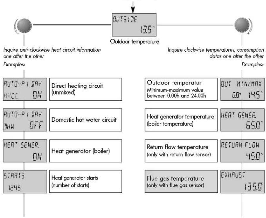
This button displays all plant temperatures and states of all circuits. The information can be requested according to the direction with the rotary-push button.
Turning rotary-push button clockwise
displays from all plant-specific temperatures
- the actual values and
- the nominal values (pressing rotary-push button)
- meter readings such as consumption data etc.
Turning rotary-push button anti-clockwise
displays from direct heating circuit resp. DHW circuit
- operational mode (holiday, absence, party, auto etc.)
- timer programm P1(P2 and P3 only when released)
- heating mode (daytime-, reduced-, ECO-mode)
- identification (direct circuit HC, hot water circuit DHW)
- status of heating- and DHW charging pump (on, off)

flowchart
graph TD
    A["OPER. HOURS 258"] --> B["THERMOSTAT HCC OFF"]
    B --> C["ROOMTEMP HC 210°"]
    C --> D["Heat generator run time number of service hours"]
    D --> E["Room thermostat function 2) room max. temp. delimitation"]
    E --> F["Room temperature 2) Direct heating circuit"]
    F --> G["Hydraulic pressure 1) (only it pressure sensor is present)"]
    G --> H["Hot-water temperature (electronically controlled)"]
    H --> I["Hot-water thermostat 1) (mechanically controlled)"]
    I --> J["THERMOSTAT DHW OFF"]
    J --> K["HYDRU PRESS 14"]
    K --> L["BHW 520° resp."]
shows
- operating status (on, off)
- number of service hours
- number of starts
of heat generator, boiler etc.
shows
- room thermostat function (heating on, off)
- current room temperature
if room sensor is activated
shows
- water pressure
if pressure sensor is present
1) display dependent on the type of heat generator
^2 will be displayed only if the room sensor was activated before

flowchart
graph TD
    A["Standard display (Example: Operational mode AUTOMATIC)"] --> B["Entry into the level selection"]
    B --> C["3sec"]
    C --> D["press knob for approx. 5 seconds"]
    D --> E["Select Level"]
    E --> F["TIME-DATE"]
    F --> G["TIME"]
    G --> H["back forward"]
    H --> I["YEAR"]
    I --> J["Back"]
    J --> K["SELECT CIRCUIT HC (Heating) DHW (Hot water)"]
    K --> L["SELECT CIRCUIT HC (Heating) DHW (Hot water)"]
    L --> M["WEEKDAY (Mo-Su) Heating cycle (1...3) Copying function"]
    M --> N["Back forward back"]
    N --> O["LANGUAGE"]
    O --> P["back forward back"]
    P --> Q["TIME PROGRAM P1 P1-P3"]
    Q --> R["back forward back"]
    R --> S["LEGIONELLA PROTECTION Day 1-7"]
    S --> T["Forward back forward"]
    T --> U["UNMIXED HEATING CIRCUIT"]
    U --> V["REDUCED HEATING ECO/Reduction"]
    V --> W["ECO-Temperature reduced nominal DHW-value"]
    W --> X["forward"]
    X --> Y["HEATING SYSTEM m-value Underfl./rad./conv."]
    Y --> Z["HEATING SYSTEM m-value Underfl./rad./conv."]
    Z --> AA["HEATING CIRCUIT NAME"]
    AA --> AB["UNMIXED HEATING CIRCUIT"]

flowchart
graph TD
    A["DAY-MONTH"] --> B["back"]
    B --> C["forward"]
    C --> D["CHANGEOVER Summer-Wintertime"]
    D --> E["back"]
    E --> F["forward"]

flowchart
graph TD
    A["HEATING START selected cycle"] --> B["●"]
    B --> C["HEATING END selected cycle"]
    C --> D["●"]
    D --> E["TEMPERATURE selected cycle"]
    E --> F["●"]

flowchart
graph TD
    A["OPERATING MODE\ncommon (1)\nseparate (2)"] --> B["back"]
    B --> C["forward"]
    C --> D["SUMMER\nswitching off"]
    D --> E["back"]
    E --> F["forward"]
    F --> G["PARAM.-RESET\nReset to factory\npreset"]
    G --> H["back"]
    H --> I["forward"]
Selection and modification of parameters and setting values
Entering into the programming level, principally the operating times level (TIME PROGRAMS) appears at first. All other levels, such as
- SYSTEM
- DHW
- UNMIXED CIRCUIT
- DATE-TIME
can be selected directly via rotary-push button
By pressing the rotary-push button, the selected flashing level is activated; the first value resp. parameter appears flashing. If necessary, it can be modified via the rotary-push button and accepted by pressing again. If necessary, the following parameters can be treated in the same way.
Re-entry into the level selection is done via the info button ⓘ, re-entry into the standard display via the program-selection button ⓘ or automatically after approx. 60 seconds.
Programming of operating times
flowchart
graph TD
    A["Standard display"] --> B["Press for approx. 3 seconds"]
    B --> C["Enter operating times level"]
    C --> D["accept"]
    D --> E["Select heating circuit"]
    E --> F["For example unmixed heating circuit HC"]
    F --> G["accept"]
    G --> H["select program P1...P3, if released"]

    style A fill:#f9f,stroke:#333
    style H fill:#ccf,stroke:#333

    note right of A: With this mode of operation individual water mode can be set up. For this factory preset standard program (P1...P3)
    Note: For programming the operation time switch-on and switch-off time each a cycle be combined with a required room cycle.
    end
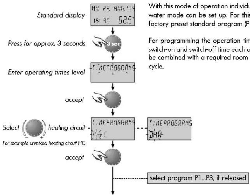
With this mode of operation individual programs, other than standard programs for heating and hot-water mode can be set up. For this purpose after selecting the heating- resp. hot-water circuit the factory preset standard program (P1) is called an can be overwritten individually.
For programming the operation times, for each week day maximum three heating cycles with one switch-on and switch-off time each are available. Further more, the heating- resp. hot-water cycle can be combined with a required room temperature resp. hot-water temperature for the duration of the cycle.
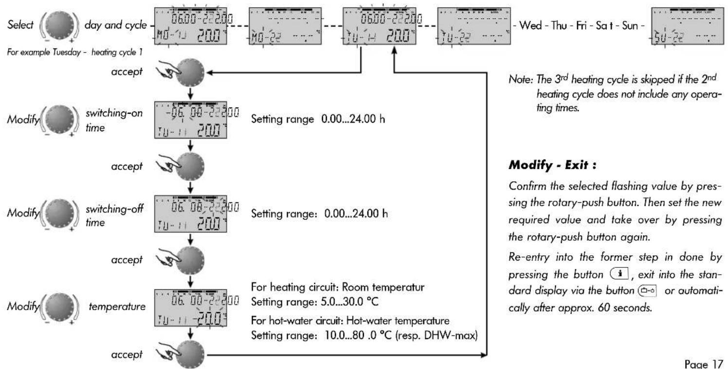
flowchart
graph TD
    A["Select day and cycle"] --> B["Day 06:00-22:00"]
    B --> C["Day 06:00-22:00"]
    C --> D["Day 06:00-22:00"]
    D --> E["Wed - Thu - Fri - Sat - Sun"]
    E --> F["Day 06:00-22:00"]
    F --> G["Day 06:00-22:00"]
    G --> H["Day 06:00-22:00"]
    H --> I["Day 06:00-22:00"]
    I --> J["Day 06:00-22:00"]
    J --> K["Day 06:00-22:00"]
    K --> L["Day 06:00-22:00"]
    L --> M["Day 06:00-22:00"]
    M --> N["Day 06:00-22:00"]
    N --> O["Day 06:00-22:00"]
    O --> P["Day 06:00-22:00"]
    P --> Q["Day 06:00-22:00"]
    Q --> R["Day 06:00-22:00"]
    R --> S["Day 06:00-22:00"]
    S --> T["Day 06:00-22:00"]
    T --> U["Day 06:00-22:00"]
    U --> V["Day 06:00-22:00"]
    V --> W["Day 06:00-22:00"]
    W --> X["Day 06:00-22:00"]
    X --> Y["Day 06:00-22:00"]
    Y --> Z["Day 06:00-22:00"]
    Z --> AA["Day 06:00-22:00"]
    AA --> AB["Day 06:00-22:00"]
    AB --> AC["Day 06:00-22:00"]
    AC --> AD["Day 06:00-22:00"]
    AD --> AE["Day 06:00-22:00"]
    AE --> AF["Day 06:00-22:00"]
    AF --> AG["Day 06:00-22:00"]
    AG --> AH["Day 06:00-22:00"]
    AH --> AI["Day 06:00-22:00"]
    AI --> AJ["Day 06:00-22:00"]
    AJ --> AK["Day 06:00-22:00"]
    AK --> AL["Day 06:00-22:00"]
    AL --> AM["Day 06:00-22:00"]
    AM --> AN["Day 06:00-22:00"]
    AN --> AO["Day 06:00-22:00"]
    AO --> AP["Day 17 Day 17"]

    subgraph Flashing Value
        direction LR
        A -->|Accept| A
        B -->|Accept| B
        C -->|Accept| C
        D -->|Accept| D
        E -->|Accept| E
        F -->|Accept| F
        G -->|Accept| G
        H -->|Accept| H
        I -->|Accept| I
        J -->|Accept| J
        K -->|Accept| K
        L -->|Accept| L
        M -->|Accept| M
        N -->|Accept| N
        O -->|Accept| O
        P -->|Accept| P
        Q -->|Accept| Q
        R -->|Accept| R
        S -->|Accept| S
        T -->|Accept| T
        U -->|Accept| U
        V -->|Accept| V
        W -->|Accept| W
        X -->|Accept| X
        Y -->|Accept| Y
        Z -->|Accept| Z
        AA -->|Accept| AA
        AB -->|Accept| AB
        AC -->|Accept| AC
        AD -->|Accept| AD
        AE -->|Accept| AE
        AF -->|Accept| AF
        AG -->|Accept| AG
        AH -->|Accept| AH
        AI -->|Accept| AI
        AJ -->|Accept| AJ
        AK -->|Accept| AK
        AL -->|Accept| AL
        AM -->|Accept| AM
        AN -->|Accept| AN
        AO -->|Accept| AO
        AP -->|Accept| AP
        AQ -->|Accept| AQ
        AR -->|Accept| AR
        AS -->|Accept| AS
        AT -->|Accept| AT
        AU -->|Accept| AU
        AV -->|Accept| AV
        AW -->|Accept| AW
        AX -->|Accept| AX
        AY --> Y
    end

    Note:
    note1["Note: The 3rd heating cycle is skipped if the 2nd heating cycle does not include any operating times."]
    note1 -.-> note1
Copy operating times

flowchart
graph TD
    A["Standard display"] --> B["Push for approx. 3 seconds"]
    B --> C["Enter operating times level"]
    C --> D{accept}
    D -->|Yes| E["select heating circuit"]
    D -->|No| F{accept}
    E --> G["For example unmixed heating circuit HC"]
    G --> H{select program P1...P3, if available}
    H --> I["copy functionSelect"]
    I --> J["06:00-2:00"]
    J --> K["06:00-2:00"]
    K --> L["06:00-2:00"]
Programming of operating times includes a extensive copying function which allows to copy any day of the week to other days (Mo..Su) resp. to the whole week (1-7) or parts of a week such as workdays (1-5) or weekends (6-7).

flowchart
graph TD
    A["Start"] --> B["Select source\nExample: Monday"]
    B --> C{accept}
    C -->|Yes| D["Copy from -MMO"]
    C -->|No| E["Copy TO -1-55"]
    D --> F["Setting range: Monday (MO)...Sunday (SU)"]
    E --> G["Setting range: Days (MO...SU), whole week (1-7), Working days (1-5), weekend (6-7)"]
    F --> H["Copy DAY 00K"]
    G --> I["Copy TO -65-77"]
    H --> J["Confirmation"]
    I --> K["Source and destination are identical"]
    J --> L["If necessary select and take over further destinations in the same way."]
    K --> M["Select next destination\nExample: Saturday and Sunday"]
    L --> N["etc.."]
Modify - Exit :
Confirm the selected flashing value by pressing the rotary-push button. Then set the new required value and take over by pressing the rotary-push button again.
Re-entry into the former step in done by pressing the button i exit into the standard display via the button o on automatically after approx. 60 seconds.
Reloading of standard time programs - deleting of individual time programs

flowchart
graph TD
    A["Standard display"] --> B["Push for approx. 3 seconds"]
    B --> C["Enter operating times level"]
    C --> D{TIMEPROGRAMS}
    D -->|accept| E["select default time"]
    D -->|accept| F["select heating circuitSelect"]
    E --> G["DEFAULT-TIME"]
    F --> H["DEFAULT-TIME"]
    G --> I["Re-entry into the former step in done by pressing the button i, n exit into the standard display via the button = -o or automatically after approx. 60 seconds"]
    H --> J["DEFAULT-TIME ALL-"]
The standard programs do not get lost by overwriting with individual programs. Individual programs however are cancelled at a later call of the corresponding standard programs and have to be set up again. For this purpose individual switching-on and switching-off times should always be noted (see level TIME PROGRAMS - table for individual programs).
Modify - Exit :
Confirm the selected flashing value by pressing the rotary-push button. Then set the new required value and take over by pressing the rotary-push button again.
Re-entry into the former step in done by pressing the button i, exit into the standard display via the button =or automatically after approx. 60 seconds.
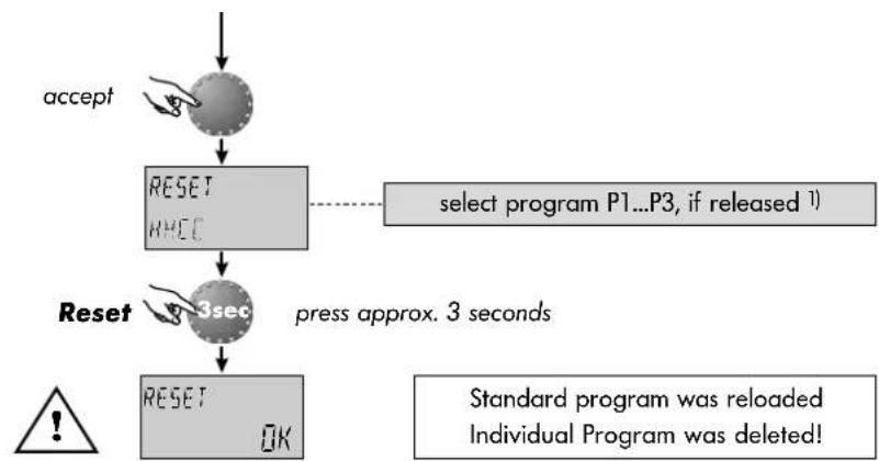
flowchart
graph TD
    A["accept"] --> B["RESET\nRMCC"]
    B --> C["3sec"]
    C --> D["RESET\nOK"]
    E["select program P1...P3, if released 1"] -.-> C
    F["Standard program was reloaded\nIndividual Program was deleted!"]
    G["Reset"] --> C
    H["3sec"] --> C
    I["Press approx. 3 seconds"] --> C
Standard time programs
Standard operating-times program P1
| Circuit Day Heating from...to | |
| Unmixed heating circuit (HC) | Mo-Su 06.00 - 22.00 h |
| Domestic hot water (DHW) | Mo-Su 05.00 - 22.00 h |
Standard operating-times program P1 1)
| Circuit Day Heating from...to | |
| Unmixed heating circuit (HC) | Mo-Th 06.00-08.00 16.00-22.00hFr 06.00-08.00 13.00-22.00hSa-Su 07.00-23.00h |
| Domestic hot water (DHW) | Mo-Th 05.00-08.00 15.30-22.00hFr 05.00-08.00 12.30-22.00hSa-Su 06.00-23.00h |
^1) see level SYSTEM - parameter PROGRAM
Standard operating-times program P3 1)
| Circuit Day Heating from...to | |
| Unmixed heating circuit (HC) | Mo-Fr 07.00-18.00 hSa-Su reduced heating |
| Domestic hot water (DHW) | Mo-Fr 06.00-18.00 hSa-Su reduced heating |
Table for individual operating times and programs
| Operating times program P1 Operating times program P2 Operating times program P3 | |||||||||||||||||||
| Unmixed heating circuit (HC) | Day | 1^st cycle | 2^nd cycle | 3^rd cycle | 1^st cycle | 2^nd cycle | 3^nd cycle | 1^st cycle | 2^nd cycle | 3^rd cycle | |||||||||
| From till | from till | from till | from till | from till | from till | from till | from till | from till | |||||||||||
| Mon | |||||||||||||||||||
| Tue | |||||||||||||||||||
| Wed | |||||||||||||||||||
| Thu | |||||||||||||||||||
| Fri | |||||||||||||||||||
| Sat | |||||||||||||||||||
| Sun | |||||||||||||||||||
| Domestic hot-water circuit (DHW) | Day | 1^st cycle | 2^nd cycle 2 | 3^rd cycle | 1^st cycle | 2^nd cycle | 3^rd cycle | 1^st cycle | 2^nd cycle | 3^rd cycle | |||||||||
| from till | from till | from till | from till | from till | from till | from | till | from till | from till | ||||||||||
| Mon | |||||||||||||||||||
| Tue | |||||||||||||||||||
| Wed | |||||||||||||||||||
| Thu | |||||||||||||||||||
| Fri | |||||||||||||||||||
| Sat | |||||||||||||||||||
| Sun | |||||||||||||||||||
TIME-DATE

flowchart
graph TD
    A["Entry:"] --> B["set time"]
    B --> C["set year"]
    C --> D["set day & month"]
    D --> E["set changeover"]

    F["TIME - DATE"] --> G["TIME - 18:45"]
    G --> H["YEAR - 2005"]
    H --> I["BAY-MONTH - MMOS 22.08"]
    I --> J["CHANGE - SU-WI AUTO"]
Current time
Setting range:
0.00...24.00 h
Calender year
Setting range:
2001...2099
Calender day-month-weekday
Weekday is set automatically
Time changeover mode
Setting range:
Automatic: last Sunday in March & Oct.
Manual: no time reset
Entry: see » Programming level - Level summary « .
Exit: via button


Modify: Confirm selected flashing parameter by pressing
the rotary-push button. Then set the new required value via and accept by pressing the rotary-push button again. If necessary, correct the following parameters in the same way.
The values to the left are factory presets and normally need not be updated. If in some exceptional cases corrections should be necessary, the values can be adapted to the real conditions.
The internal pre-programmed calender provides an automatic time changeover at the yearly repeating summer-wintertime dates.
If required, the automatic time changeover can be switched off (manual reset).
SYSTEM


next parameter

This level includes general delimiting parameters and options referring to the corresponding heating system
Language
Setting range:
DE = German GB = English FR = French
IT = Italian NL = Dutch ES = Spanish
PT = Portuguese HU = Hungarian CZ = Czech
PL = Polish RO = Romanian RU = Russian
TR = Turkish S = Swedish N = Norwegian
Factory preset: DE
All information that appears in the display, is available in a number of languages. After entry as first parameter appears the language selection. The required language can be selected and accepted according to the above assignment.
Operating times program
Setting range: P1, P1-P3
Factory preset: P1
This parameter specifies the number of the released time programs. With setting P1 only one operating-times program is available, with setting P1-P3 all three programs are released and can be selected for programming operating times.
Entry: see » Programming level - Level summary « .
Exit: via button

or automatically after 60 seconds
Modify:
Confirm selected flashing parameter by pressing the rotary-push button. Then set the new required value via and accept by pressing the rotary-push button again. If necessary, correct the following parameters in the same way.
Application:
Use of the instrument at the corresponding language area.
Application:
Shift work, different programs for summer, transition period, winter etc.

next parameter
Control mode
Setting range: 1 = common mode 2 = separated mode
Factory preset: 1
Common control mode:
The selected operational mode (via button ☐-☐-☐-for Holiday, Absence, Party, Automatic etc.) applies to the heating circuit and to the hot-water circuit together.
Separated control mode:
The heating- and hot-water circuit can be assigned with own operational mode.
Application: Objects with uniform seizure character (One-family houses etc).
Application: Objects with different use of heating and hot-water (for example heating operation in Holiday mode, hot-water permanently in reduced mode).

flowchart
graph TD
    A["Select Circuit"] --> B["OP. MODE"]
    B --> C["Unmixed circuit (HC), hot-water circuit (DHW)"]
    C --> D["accept"]
    D --> E["further operation see »Operational mode s"]
next parameter

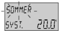
Summer switch-off
Setting range: OFF, 10.0 to 30,0 °C
Factory preset: 20.0 °C
This parameter specifies the heating delimiting value regarding the average resp. current outdoor temperature and puts the heating plant automatically out of service as soon as the outdoor temperature exceeds the set heating delimiting value. During summer switch-off the pump of the heating circuit is activated each day for approx. 10 seconds to protect it against corrosion.
With setting OFF the summer switch-off is not effective.
Hot water preparation is not affected by summer switch-off.


Parameter-reset
This function resets all individually entered values in the programming level to factory preset.
Exception: Time-date, operating times
Reset: Press rotary-push button for approx. 5 sec. while indication SET is flashing, until standard display appears.
Note: The active summer switch-off appears on the standard display with a sunshade symbol.

Summer switch-off activated
Application: All objects which do not require a heating operation during summertime
Important: Reset may only be executed if all individually entered values shall be replaced by the factory preset values!
DOMESTIC HOT WATER

flowchart
graph TD
    A["Entry:"] --> B["NIGHT 40.0°"]
    B --> C["next parameter"]
    C --> D["LEG ON PROT. DAY OFF"]
This level includes the necessary parameters for programming the hot-water circuit except the hot-water operating-times.
Hot-water economic temperature
Setting range: 5.0 °C up to the required hot water temperature Factory preset: 40.0 °C
This parameter determines the amount of the reduced hot-water temperature outside the hot-water operating times (between the hot-water cycles) as well as in the operational mode ABSENCE for the duration of absence.
Legionella protection (day)
Setting range: OFF, MO...SU, ALL Factory preset: OFF
The legionella protection serves to avoid a legionella infestation inside the hot-water tank and is activated on the selected week-day (Mon to Sun) or every day at 2.00 o'clock. If the hot-water temperature should drop below 65 °C, the tank is reloaded.
With setting OFF this function is not effective.
Entry: see » Programming level - Level summary « .
Exit: via button ☐ or automatically after 60 seconds
Modify: Confirm selected flashing parameter by pressing the rotary-push button. Then set the new required value via and accept by pressing the rotary-push button again. If necessary, correct the following parameters in the same way.
Application: Base temperature inside the hot-water tank in order to avoid a cooling down of the tank.
Note: This parameter is skipped if a hot-water thermostat is used instead of an electronic hot-water sensor.
Note: Other legionella protection times can be regulated exclusively by the heating plant specialist.
Important: Danger of scalding! Use thermostatic mixing valve on DHW outlet.
Unmixed heating circuit (direct circuit)
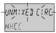

next parameter

This level includes the parameters required for programming the heating circuit with the exception of the related operating-times programs.
Reduced heating mode
Setting range: ECO, RED
Factory preset: ECO
During the reduced operation the following modes can be selected:
ECO mode: At outdoor temperatures above the set plant frost protection the heating circuit is switched off completely. At temperatures below frost protection the heating circuit is controlled with reduced heating characteristic according to the required reduced temperature (see »Temperature setting«).
RED mode: During the reduced mode the heating circuit pump remains activated. The heating circuit is controlled according to the reduced heating characteristic, the temperature does not drop below the set minimum temperature value.
Entry: see » Programming level - Level summary « .
Exit: via button ☐or automatically after 60 seconds
Modify: Confirm selected flashing parameter by pressing the rotary-push button. Then set the new required value via and accept by pressing the rotary-push button again. If necessary, correct the following parameters in the same way.
Application: Objects with high insulation values
Application: Objects with low insulation values

Adaptation to the heating system
Setting range: 1,00 to 10.0
Factory preset: 1,30
This parameter refers to the type of the heating system and has to be adapted to the power characteristic of the corresponding consumer (underfloor systems, radiator, convector). The setting value specifies the curvature of the heating curve of the selected weather dependent heating circuit and compensates the system-related efficiency losses at lower temperatures by a progressive heating curve in conformity with the adjustment.

Heating circuit name
This is used to assign an individual, 5 character, abbreviated name to each heating circuit.
No individual name is assigned if the setting "empty" is used. The default abbreviated name appears.
- The character that blinks can be altered using the rotary knob according to the code number and accepted by pressing the knob once. The remaining characters can be altered in the same way.
• The individual heating circuit name display appears
- in the menu
- in the parameter tree
- in the info level
Applications:
The following setting values are recommended for the below-mentioned applications
| Setting value | Application |
| 1.00...1.10 | Heating curve for underfloor heating systems or other static heating surfaces |
| 1.30...2.20 | Normal standard heating curves for radiators |
| 3.00...4.00 | Heating curves for convectors |
| 4.00...10.0 | Special heating curves for ventilators with high starting temperatures |
Alarm messages

Example for alarm message »sensor« (short or open circuit) Error code 10...20
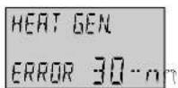
Example for alarm message »heat generator« (flue gas temperature exceeded) Error code 30...40...
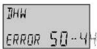
Example for logical alarm messages (control functions) Error code 50. ..60
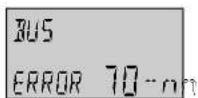
Example for alarm message »data bus« (address error) Error code 70
^1) For these alarm messages the error codes of the heat generator in the corresponding installation manuals have to be considered.
The instrument is equipped with an extensive error diagnostic features. The error displayed takes priority over other displays and varies dependent on the model in question.
For alarm messages from burner control (ERROR Xn:m) the error codes in the corresponding installation manuals have to be considered.
Note: Alarm messages only appear alternating with the standard display.

In case of alarm messages the heating specialist always has to be informed!
Personal notes
Seite 31
Technical specification
Supply voltage: Via data bus (DC-safety voltage by EN 60730)
Power consumption: 300 mW
Bus interface: T2B or OpenTherm according to model
Ambient temperature: 0...60 °C
Storage temperature: -25...60 °C
Protection type acc. to EN 60529: IP 30
Protection class acc. to EN 60730: III
Approval according to: VDE 60730
Casing dimensions (BxHxD): 90 x 138 x 28 mm
Casing material: ABS, antistatic
Electrical connections: 2-wire mode with plugable connection
Recommended cable: J-Y(St)Y 2 x 2 x 0.6 mm
Max. length of cable: 50 m
Data and timer back up: Min. 5 years from date of delivery
Accuracy of the internal clock ± 2s/day
Weight: Approx. 150 g
- Operating Instructions
- Table of contents
- USER LEVEL
- PROGRAMMING LEVEL
- General operation
- Operating instruments
- Operation
- Start-up
- Language selection
- Device identification
- Basic display
- Temperature settings
- Adjustment (standard display mode only):
- Operational mode selection for heating and hot water
- Quick operational mode selection
- Short-time operational modes
- Direct automatic mode
- Manual hot water loading
- Setting the heating characteristics (heating curve)
- Turning rotary-push button clockwise
- Turning rotary-push button anti-clockwise
- shows
- Selection and modification of parameters and setting values
- Programming of operating times
- Copy operating times
- Modify - Exit :
- Reloading of standard time programs - deleting of individual time programs
- Standard time programs
- Current time
- Calender year
- Calender day-month-weekday
- Time changeover mode
- SYSTEM
- Language
- Operating times program
- Control mode
- Common control mode:
- Separated control mode:
- Summer switch-off
- Parameter-reset
- DOMESTIC HOT WATER
- Hot-water economic temperature
- Legionella protection (day)
- Unmixed heating circuit (direct circuit)
- Reduced heating mode
- Adaptation to the heating system
- Heating circuit name
- Applications:
- Alarm messages
- Personal notes
- Technical specification
Brand : Atag
Model : BrainZ
Category : Thermostat