
IPA 424 T - Receiver LD Systems - Free user manual and instructions
Find the device manual for free IPA 424 T LD Systems in PDF.

| Product Type | Power amplifier for fixed installations |
| Brand | LD Systems |
| Model | IPA 424 T |
| Channels | 4 |
| Output circuit | Class D |
| Output power (1 kHz, 4 Ω) | 4 x 240 W (1.5 s sine wave) |
| Power supply | Wide-range switching power supply with power factor correction |
| Power connector | 3-pin IEC plug |
| Output impedances | Low impedance (4 Ω min.), high impedance (70 V / 100 V) |
| Audio inputs | 4 balanced line inputs (6-pin terminal block, pitch 3.81 mm) |
| Speaker outputs | 4 outputs (4-pin terminal block, pitch 5.08 mm) |
| DSP | Yes (ADAU1452 Sigma DSP, 48 kHz, 24-bit) |
| Remote control bus | CAN (RJ45) with included termination |
| Extension port | For Ethernet or Ethernet + Dante card (optional) |
| Cooling | Temperature-controlled active, 2 zones, front/rear airflow |
| Dimensions (W x H x D) | 483 x 44.5 x 425 mm (19" rack, 1U) |
| Weight | 11.36 kg |
| Operating temperature | 0 °C to +40 °C (max. 60% relative humidity) |
| Maintenance and cleaning | Disconnect the device; clean with a dry cloth only |
| Safety | Protections: DSP limiter, overcurrent, DC, overheat, short circuit, auto standby |
| Spare parts and repairability | Repair by an authorized professional; spare parts available on request from the manufacturer |
| Warranty | See terms on the manufacturer's website |
Frequently Asked Questions - IPA 424 T LD Systems
User questions about IPA 424 T LD Systems
0 question about this device. Answer the ones you know or ask your own.
Ask a new question about this device
Download the instructions for your Receiver in PDF format for free! Find your manual IPA 424 T - LD Systems and take your electronic device back in hand. On this page are published all the documents necessary for the use of your device. IPA 424 T by LD Systems.
USER MANUAL IPA 424 T LD Systems
SAFETY INFORMATION 3
INTRODUCTION
FEATURES
PACKAGING CONTENT 5
CONNECTIONS, CONTROLS AND DISPLAY ELEMENTS 5
ASSIGNMENT OF THE TERMINAL BLOCK CONNECTIONS
AND SETUP EXAMPLES 11
TECHNICAL DATA 11
MANUFACTURER'S DECLARATIONS 14
DEUTSCH
This device was developed and manufactured under high quality requirements to ensure smooth operation for many years. As a manufacturer of first-class audio products, LD Systems, its name, and long-standing experience, are inextricably linked with such standards. Please read this user manual carefully to ensure you can quickly make the best use of your new LD Systems product.
Further information about LD SYSTEMS is available on our website WWW.LD SYSTEMS.COM
SAFETY INFORMATION
- Please read this user manual carefully.
- Keep all information and instructions in a safe place.
- Follow the instructions.
- Observe all warnings. Do not remove any safety instructions or other information from the device.
- Only use the device as properly intended.
- Only use stable and suitable stands and fixtures and fittings (for fixed installations). Make sure wall brackets are properly installed and secured. Make sure that the device is securely installed and cannot fall down.
- Please observe the safety regulations in place in your country when installing the device.
- Do not install or operate the device near heating elements, heat storage units, stoves, or other sources of heat. Make sure that the device is always installed so that it is adequately cooled and cannot overheat.
- Do not put any sources of ignition (e.g., burning candles) on the device.
- Ventilation slots must not be blocked.
- Keep a minimum distance of 7.87 inches to the side and top of the device.
- Do not operate the device near water. Do not allow the device to come into contact with flammable materials, liquids, or gases. Avoid direct sunlight!
- Make sure that no dripping or splashing water can get into the device. Do not put containers filled with liquid (e.g., vases or drinking containers) on the device.
- Make sure that no objects can fall into the device.
- Only operate the device with accessories recommended and provided by the manufacturer.
- Do not open the device or make any modifications to it.
- After the device is connected, check all cable paths to prevent any damage or accidents (e.g., tripping hazards).
- During transport, make sure that the device does not fall down and potentially cause damage/injury to property and persons.
- If your device stops working properly, if liquids or objects have penetrated the device, or if the device has been damaged in any other way, switch it off immediately and unplug it from the power outlet (if the device is active). Only authorized specialists may repair the device.
- Use a dry cloth to clean the device.
- Observe all waste disposal laws applicable in your country. Separate plastic and paper/cardboard when disposing of packaging.
- Plastic bags must be kept out of the reach of children.
- Any changes and modifications made by the user, which have not been expressly agreed upon with the party responsible for compliance, could void the user's authority to operate the device.
FOR DEVICES CONNECTED TO A POWER SUPPLY
- CAUTION: If the device's power cable has a protective contact, it must be connected to an outlet with a protective ground conductor. Never deactivate the power cable's protective ground conductor.
- The mains outlet shall be installed near the equipment and shall be easily accessible, to be able to disconnect the device completely from Mains.
- Do not switch the device on right after it has been subjected to strong temperature fluctuations (e.g., after transport).
Humidity and condensation may have damaged the device. Only switch the device on once it has reached room temperature.
-
Before plugging the device into the outlet, first check whether the voltage and frequency of the power supply correspond to the values specified on the device. If the device has a voltage selector switch, only plug the device into the outlet if the device values match the power supply values. Contact an electrician if the supplied power cable or adapter does not fit into your power outlet.
-
Do not step on the power cable. Make sure that live cables are not kinked, especially at the power socket or at the power adapter and the device socket.
- When laying out the device cables, always ensure that the power cable or power adapter can be freely accessed at all times. Always disconnect the device from the power supply when it is not being used or when you want to clean it. Always hold the plug or adapter when unplugging the power cable or power adapter; do not unplug it by pulling the cable. Never touch the power cable and power adapter with wet hands.
- If possible, do not switch the device on and off in quick succession; this could negatively impact the lifespan of the device.
- I i t r t
- To completely disconnect the device from the power supply, unplug the power cable or power adapter from the outlet
- If your device has a lockable power supply, the corresponding device plug must be unlocked before it can be disconnected. This also means, however, that if the cable is pulled, it can cause the device to slip/fall and either cause injury to persons and/or cause other damage. Cables should therefore be laid out carefully.
- Remove the power cable and power adapter from the outlet if there is a risk of lightning or if you will not be using the device for a long period of time.
- The device is not intended for use by persons (including children) with reduced physical, sensory, or mental capabilities or with insufficient experience and knowledge.
- Children must be instructed not to play with the device.
- Do not use the device if its power cable is damaged. The power cable must be replaced with a suitable cable or a special assembly from an authorized service center.


CAUTION
Never remove the cover - there is a risk of electrical shock. The device does not contain any parts inside requiring repair or servicing by the operator. Only allow qualified service technicians to carry out maintenance and repairs.
To prevent electrical shock, do not touch exposed speaker cables/wires while the amplifier is in operation!

High output voltage; risk of electrical shock! A trained person must install the wiring for the loudspeaker connection terminals using prefabricated wiring systems!
CLASS 2 WIRING

Warning! This symbol indicates hot surfaces. Specific housing parts can become hot during operation. Allow the device to cool for at least ten minutes after use. Only then can it be transported or touched.

Warning! This device is designed for use up to a maximum height of 6,562 feet above sea level.

Warning! This device is not intended for use in tropical climates.

Protective earth (ground)
To identify any terminal which is intended for connection to an external conductor for protection against electric shock in case of a fault, or the terminal of a protective earth (ground) electrode.

"ON" (power)
To indicate connection to the mains, at least for mains switches or their positions, and all those cases where safety is involved.

"OFF" (power)
To indicate disconnection from the mains, at least for mains switches or their positions, and all those cases where safety is involved.
WARNING: HIGH-VOLUME AUDIOPRODUCTS!
This device is intended for professional use. The commercial operation of this device is subject to applicable national regulations and directives for accident prevention. As the manufacturer, Adam Hall is legally bound to specifically point out potential health risks. Hearing damage caused by high volumes and prolonged exposure: Using this product can generate high sound pressure levels (SPL), which can cause irreparable hearing damage to artists, employees, and audiences. Avoid prolonged exposure to high volumes above 90 dB.
INTRODUCTION
IPA 424 T and IPA 412 T are DSP-based 4-channel installation amplifiers in 19 rack format specially developed for professional audio installations. They have integrated transformers per channel and offer connections for 100 V/70 V and Low-Z systems up to 4 Ohm. For optimal energy efficiency, the devices have auto standby switches. A slot for optional expansion cards enables the IPA amplifier, including all internal DSP parameters to be controlled via Ethernet and, thanks to the Dante AoIP connectivity, to be integrated into larger installation networks. The IPA series can also interact with remote units and paging microphones from LD Systems via a REMOTE audio and control bus based on a CAN (Controller Area Network) architecture. This combination of powerful functions makes the IPA series the best choice for permanent installation.
FEATURES
Professional 4-channel DSP-based class D power amplifier
- 4 x 240W (IPA 424 T) or 4 x 120W (IPA 412 T) @ 4 ohm / 100V / 70V
- 4 balanced line inputs and 4 speaker outputs with terminal block connections
- User-friendly front panel design with signal, limit, protection, mute and bridge mode LEDs per channel
- Clip LEDs for the inputs and level controls for the outputs on the back
- On/off switchable auto standby mode
- Stereo/parallel/bridge mode selector per channel pair
- Toroidal output transformer per channel
- Low-impedance outputs, completely separated from the output transformers, for optimal audio quality in Low-Z applications
DSP presets with HP and LP filter which can be activated via DIP switch
- Speaker protection circuits: DSP limiter, overcurrent, direct current, overheating, short circuit
- The REMOTE audio and control bus is based on CAN architecture (Controller Area Network) and enables interaction with future remote control panels and paging microphones
- Slot for future optional expansion cards:
- An Ethernet expansion card providing access to all internal DSP settings and the analog input gain and increases the input dynamic range by up to 10 dB
-
An Ethernet + Dante expansion card with the same functionality as the Ethernet expansion card plus Dante connectivity
-
Fault relays with terminal block connections per channel pair
Universal wide-range PFC switching power supply - Temperature-controlled active cooling with low-noise fans in 2 zones
PACKAGING CONTENT
- 1x LD Systems IPA 424 T or IPA 412 T installation amplifier with pre-assembled rack brackets
- 2 x 6-pole terminal blocks for the audio inputs (pitch 3.81 mm)
- 4×4-pole terminal blocks for the speaker outputs (pitch 5.08 mm)
- 2 x 3-pole terminal blocks for the fault relay connections (pitch 3.81 mm)
- 1xR45 REMOTE bus terminating resistor
- 1xIEC power cable
- 1x user manual
CONNECTIONS, CONTROLS AND DISPLAY ELEMENTS
Note: The connections, controls and display elements for both models IPA 424 T and IPA 412 T are identical.

1 POWER CONNECTOR
IEC power connector for the device's power supply. A suitable power cable is provided.
2 FUSE
Fuse holder for 250 V miniature fuses (5 × 20 mm). CAUTION: Only replace the fuse with a fuse of the same type (T10AL/100-120V; T5AL/220-240V). See information on the housing. If the fuse blows repeatedly, please contact an authorised service centre.
3 ON/OFF
Rocker switch to turn the device on and off.
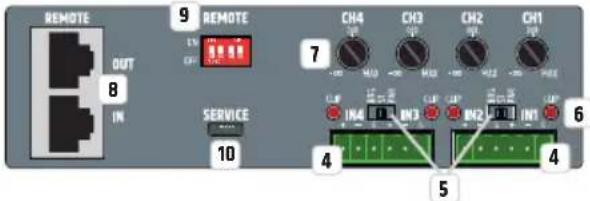
INPUT SECTION
4 IN1-IN4
Two 6-pole terminal block connections for input channels 1 and 2 or 3 and 4. Pins +, - and G form the balanced line input of the corresponding channel; suitable terminal blocks are included in the packaging.
BRG/ST/PAR
3-way switch to adjust the channel mode.
BRG (bridge mode): The power amplifiers of channels 1 and 2 or 3 and 4 are combined to provide more powerful mono power amplifiers. If the bridge mode is activated for channels 1 and 2, IN1 serves as a line input, and the volume is set using level control CH1. Line input IN2 and level control CH2 are deactivated. If the bridge mode is activated for channels 3 and 4, IN3 serves as a line input, and the volume is set using level control CH3. Line input IN4 and level control CH4 are deactivated.
Bridge operation is only available to drive low-impedance loudspeakers. When wiring the cables, ensure that the power amplifiers are correctly assigned and that the impedance of the connected loudspeaker or loudspeaker system is at least 8 ohm!
The configuration for channel 1/2 in bridge operation is: CH1 40HM = positive pole, CH2 40HM = negative pole.
The configuration for channel 3/4 in bridge operation is: CH3 40HM = positive pole, CH4 40HM = negative pole.
Caution: For safety reasons, bridge mode BRG and HI-Z mode cannot be activated at the same time. As soon as the 3-way switch is set to BRG and the corresponding DIP switch to HI-Z, an internal switching process prevents both operating modes from activating simultaneously. HI-Z mode has priority and is activated, while BRG bridge mode remains deactivated or is disabled. This state is signaled by the corresponding display field BRIDGE (No. 21) on the front panel flashing fast.
ST (stereo mode): In stereo mode, each individual line input is assigned to the corresponding speaker output, which means a signal that is present at line input IN1 is routed to speaker output CH1 and a signal that is present at line input IN2 is routed to speaker output CH2. The same also applies to channels 3 and 4. The corresponding level controls work independently of each other.
PAR (Parallel Mode): In parallel mode, a signal present at line input IN1 is routed to speaker outputs CH1 and CH2, while line input IN2 is deactivated. Level controls CH1 and CH2 are used to separately set the volume for the corresponding amplifier channel. A signal present at line input IN3 is routed to speaker outputs CH3 and CH4, while line input IN4 is deactivated. Level controls CH3 and CH4 are used to set the volume separately for the corresponding amplifier channel.
CLIP IN1-IN4
The clip LED of the corresponding channel is lit when the level of the input signal reaches -1dBFS and the channel is therefore operated at the distortion limit. Reduce the output level of the corresponding source device to avoid signal distortion.
LEVEL CONTROL CH1-CH4
Level control for the individual adjustment of the volume of speaker outputs CH1 to CH4 in stereo and parallel channel modes. As soon as the bridge mode (BRG) is activated, the level controls CH2 and CH4 have no function.
6 REMOTE IN/OUT
RJ45 connections for LD Systems REMOTE bus accessories. The accessories are connected in series to the REMOTE IN. An RJ45 bus terminating plug is included in the package. This should be connected to REMOTE OUT as standard and, under normal circumstances, not be removed from this socket. An RJ45 bus terminating plug should also be connected to the REMOTE IN of the last REMOTE bus accessory in the chain of accessory devices.
For more information on the REMOTE bus connections, see the operating instructions for the remote accessories.
9 REMOTE ON / OFF
Using the four DIP switches, the audio signal present at the REMOTE IN can be individually routed to the amplifier channels CH1 to CH4 (ON = function activated, OFF = function deactivated, DIP switch 1 = CH1, DIP switch 2 = CH2, etc). If an audio signal is present at the REMOTE IN input when the function is activated, the audio signal present at the line input of the corresponding channel is automatically muted. In this case, REMOTE IN has priority over all other line inputs.
10 SERVICE
The micro USB interface is reserved for service purposes. Do not try to create a connection to an external device.
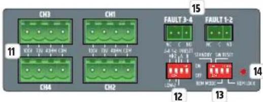
OUTPUT SECTION
11 SPEAKER OUTPUTS CH1 - CH4
Four 4-pole terminal block connectors CH1 to CH4 for the connection of speakers in the previously selected operating mode (100 V, 70 V, 4 ohm). You can find the pin assignment corresponding to the speaker system on the label between terminal block connections. The packaging includes suitable terminal blocks. Within DIP switch block no.12, use DIP switches 1 and 2 to select the desired operating mode.
12 HI-Z / LOW-Z AND PRESET
Use DIP switch 1 and 2 to select the operating mode for each pair of speaker outputs 1/2 and 3/4 .
Speaker outputs 1 and 2: Move DIP switch 2 to the ON position for HI-Z operation (100V, 70V) and to the OFF position for LOW-Z operating mode (4 OHM).
Speaker outputs 3 and 4: Move DIP switch 1 to the ON position for HI-Z operation (100V, 70V) and to the OFF position for LOW-Z operating mode (4 OHM).
Use DIP switch 3 and 4 to select the DSP preset for speaker outputs 1/2 and 3/4. The description of the preset and corresponding DIP switch positions can be found in the table below.
| IMAGE DIP switch 3 DIP switch 4 DSP preset CH1-2 CH3-4 Use | ||||||
| 3-4 1-2 PRESET HI-Z A B ON/DIP 12:34 LOW-Z | OFF OFF All channels flat Full-range speaker | |||||
| 3-4 1-2 PRESET HI-Z A B ON/DIP 12:34 LOW-Z | OFF ON | High-pass filter on all channels (HPF 95Hz, LR 24dB) | Satellite speaker | |||
| 3-4 1-2 PRESET HI-Z A B ON/DIP 12:34 LOW-Z | ON | OFF CH1 + CH2: High-pass filter (HPF 95Hz, LR 24dB) | Satellite speaker | |||
| CH3 + CH4: Low-pass filter (LPF 95Hz, LR 24dB / HPF 30Hz, BW 24dB) | Subwoofer | |||||
| 3-4 1-2 PRESET HI-Z A B ON/DIP 12:34 LOW-Z | ON | ON | Low-pass filter on all channels (LPF 95Hz, LR 24dB / HPF 30Hz, BW 24dB) | Subwoofer | ||
SYSTEM SETTINGS AND RESET
DIP SWITCH 1 STANDBY
To activate the automatic standby function, move DIP switch 1 to the ON position. If the standby switch is activated, the amplifier will automatically switch to standby mode (energy consumption reduction) after approximately 20 minutes of no audio signal. If there is an audio signal again, standby mode automatically ends and the amplifier is ready for operation again after about three seconds; the standby LED flashes white during this time. The STANDBY LED on the front of the device is white during normal operation and red when standby mode is activated. Standby mode can also be manually terminated by pressing the standby button on the front of the amplifier.
DIP SWITCH 2 SW RESET (SOFTWARE RESET)
In order to completely restore the factory settings and to avoid volume jumps after the start-up process, set all DIP switches of the device to the OFF position, the 3-way switch for setting the channel mode to ST (stereo) and turn level controls CH1 to CH4 fully counter-clockwise - before starting the software reset. Then carry out the software reset step by step:
A. Activate the standby mode of the device (press standby button no. 16) and wait until the STANDBY indicator LED lights up red continuously. Then switch the device off (switch number 3 on the back of the device) and wait until the LED display goes out completely.
B. Move the DIP switch 2 SW RESET to the ON position.
C. Switch the device on again and wait until the standby LED on the front is permanently white (to abort the reset process now move DIP switch 2 SW RESET to the OFF position).
D. Activate the standby mode of the device and wait until the STANDBY indicator LED lights up red continuously. Then switch the device off and wait until the LED display goes out completely.
E. Move DIP switch 2 SW RESET to the OFF position.
F. Switch the device on; the software is now reset. During the reset process, the device is started fully and then shutdown again. The device is then restarted. During the restart, the successful reset is reported such that display fields SIG and BRIDGE on the front of the device light up briefly one after the other. Do not switch off the amplifier during the phase under point F and do not change any settings!
DIP SWITCH 3 REM MODE (REMOTE MODE)
DIP switch 3 REM MODE is reserved for the integration of future LD Systems remote bus accessories. More detailed information can be found in the user manual of the additional remote bus accessories. The DIP switch currently has no function.
DIP SWITCH 4 REM LOCK (REMOTE LOCK)
Move DIP switch 4 to the ON position to lock all of the device's control elements (level control, DIP switch, switch for channel mode and STANDBY button), the REM LOCK LED display permanently lights up. To unlock the control elements, move the DIP switch to the OFF position. The display LED goes out, provided that no changes have been made to the control elements on the back or value changes have been made using the Ethernet control.
14 REMOTE LOCK LED
The extended access to all internal DSP settings and the analog input amplification can take place independently of the control elements on the back using an optionally available Ethernet expansion card. The following operating states are reported by the LED REMOTE LOCK display:
| LED STATUS DESCRIPTION LOCKED | CONTROL ELEMENTS | ||
| REM LOCK | REM LOCK permanently off The control elements on the back are not locked and no changes have been made to the DSP settings using the Ethernet control. | / | |
| REM LOCK | REM LOCK blinks slowly (approx. 2 Hz) | The DSP settings are changed using the Ethernet control. The setting changes cannot be undone using the control elements on the back. In order to end this state, perform a software reset (see point 13, DIP switch 2). | / |
| REM LOCK | REM LOCK blinks quickly (approx. 8Hz) | During the Remote Lock ON state, changes were made to the control elements on the back or volume-relevant settings were changed using the Ethernet control. In order to avoid volume jumps when deactivating the Remote Lock function (Remote Lock OFF), the control elements on the back remain locked. In order to terminate this state, perform a software reset (see point 13, DIP switch 2). | All control elements on the back |
| REM LOCK | REM LOCK permanently lit The remote lock function is activated (see point 13, DIP switch 4 ON). All control elements on the front and back | ||
15 FAULT 1-2 UND FAULT 3-4
Fault relay for transmitting the device operating state to a connected monitoring or redundancy system.
FAULT 1-2: If the device is switched off, in standby mode or the protection circuit of one of the two speaker channels 1 and 2 is active, contact NC is closed to C and contact NO is opened to C. In normal operation, the NC contact is open and the NO contact is closed.
FAULT 3-4: If the device is switched off, in standby mode or the protection circuit of one of the two speaker channels 3 and 4 is active, contact NC is closed to C and contact NO is opened to C. In normal operation, the NC contact is open and the NO contact is closed.
16 EXPANSION SLOTS
Slot for future optional expansion cards:
- An Ethernet expansion card that provides access to all internal DSP settings and the analog input gain and increases the input dynamic range to 10dB
- An Ethernet + Dante expansion card with the same functionality as the Ethernet expansion card plus Dante connectivity
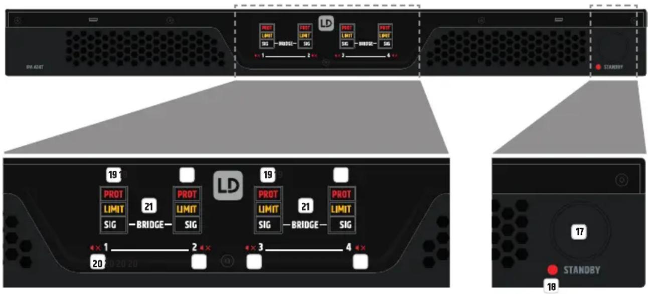
STANDBY BUTTON
The amplifier can be set into standby mode using the standby button (short press of the button); the speaker outputs are muted. To end standby mode and restore normal operation, briefly press the button again. If standby mode was manually activated by pressing the standby button, the amplifier's standby mode cannot be ended with the automatic standby function, even if there is an audio signal.
18 STANDBY LED
Two-colour LED to indicate the operating status. The LED is white when the device is operational and red in standby mode.
CHANNEL STATUS LEDs for CHANNELS 1-4
PROT (Protect) - The Protect LED displays different operating states. Details are provided in the table below.
| LED status Description Possible causes | |||
| PROT | Protect off The amplifier module for the corresponding channel functions normally. | ||
| PROT | Protect is blinking slowly (approx. 2Hz) | The device has detected a high temperature on the power supply or the amplifier board. The speaker module functions normally. The integrated temperature limiter reduces the device's output power in order to prevent the device from overheating. This status is generally displayed on all channels. As soon as the temperature falls again, the device switches to normal operation. | Concealed ventilation slots, dusty fans, long-term operation under high load, operation at very hot ambient temperatures, operation in racks without airflow. |
| PROT | Protect is blinking quickly (approx. 8Hz) | The amplifier module for the corresponding channel has detected a fault. To protect the amplifier module and the connected speaker, it is switched to mute. As soon as the fault disappears, the amplifier module switches back to normal operation. | Short circuit of the amplifier output, operation when the output impedance is too low, high-frequency signal at the output, *power supply overcurrent, *power supply fault *In the case of power supply faults, the status is displayed on all channels |
| PROT | Protect permanently lit The device has encountered a fatal fault. To protect the device and connected speaker, the device is switched to standby. This status is generally displayed on all channels. | Power supply overtemperature, amplifier board overtemperature, DC voltage signal at the output, DSP error. Turn off the device and allow it to cool. Disconnect all input and output cables and turn on the device. If the fault is still displayed after the system starts, please contact an authorised service centre. | |
The last Protect status is stored by the device. If the device is restarted, the last protect status of the respective channel/amplifier module is always displayed during the restart and then deleted.
LIMIT - The LED lights up when the corresponding channel is operated in the upper limit range. Brief flashing of the LED is not critical. To protect the system, an excessive signal level is gently reduced by the integrated limiter. If the limiter LED lights up longer or continuously, reduce the volume level.
SIG - The LED lights up when there is an audio signal on the corresponding channel.
20 MUTE SYMBOL CHANNEL1-4
The mute symbol lights up when the level control of the corresponding channel is turned fully counter-clockwise -∞ (channel is muted), or the corresponding channel is muted via the Ethernet expansion card.
21 BRIDGE LED CHANNEL 1/2 AND CHANNEL 3/4
The bridge LED of a channel pair lights up as soon as the channel bridge mode is activated for the corresponding channels (see point 5).
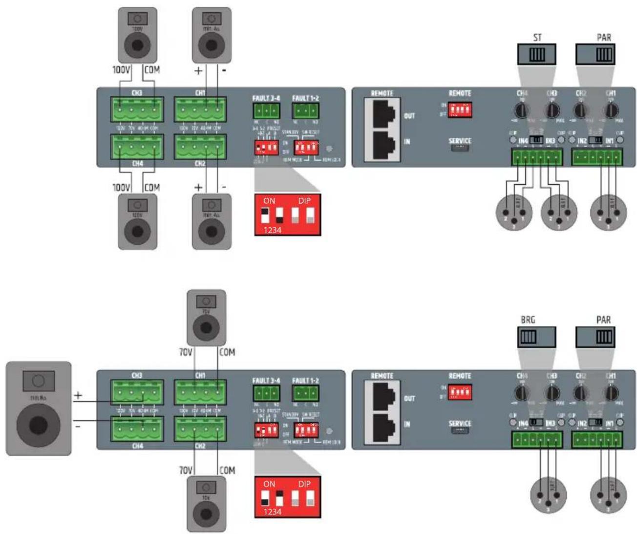
ASSIGNMENT OF THE TERMINAL BLOCK CONNECTIONS AND SETUP EXAMPLES
TECHNICAL DATA
Item description: LDIPA424T LDIPA412T
Product type: Power amplifier for fixed installations
General data
Audio channels: 4
Output circuit: Class D
Power supply: Wide-range switching power supply with PFC (power factor correction filter)
Power supply connector: 3-pole power supply socket (IEC)
Auto standby mode: Yes. Switchable (On-off)
Time to auto standby: 20 min. without audio input signal
DSP: Yes
Item description: L0IPA424T LDIPA412T
Remote bus: Yes
Display elements: Back: 4 x input signal clip LEDs, remote lock LED (red).
Front: "PROT", "LIMIT", "SIG", "BRIDGE" and mute symbol LEDs Power On/Standby LED
Front panel controls: Standby, On/Off switch (Power On/Off)
Rear panel controls: Potentiometer for output volume. Amplifier channel mode: "PAR" (Parallel), "ST" (Stereo), "BRG" (Bridge).
Remote ON/OFF. Remote locking switch. Remote mode. Standby On/Off. Switch for preset A and B.
Low-Z and high-Z switch (Per pair of channels).
Inputs: 4 x balanced line inputs, remote bus audio input
Input connections: 6-pole terminal block, pitch 3.81 mm, remote ON/OFF RJ45, service connector micro USB type B
Outputs: 4x powered speaker outputs: Low-2 (minimum 4 ohm), high-2 (70 V and 100 V).
Fault detection: 2 x NO/NC relay outputs (connected).
Output connections: Speaker outputs: 4-pole terminal block connections, pitch 5.08 mm.
Fault relays: 2 x 3-pole terminal block, pitch 3.81 mm.
Speaker cable diameter Minimum diameter (max AWG) of cable cross section is 1.5mm2 (16 AWG)
Maximum diameter (min AWG) of cable cross section is 3.31mm2 (12 AWG)
Expansion slots: Yes. For optional Ethernet or Ethernet + Dante cards
Cooling: Passive + temperature-controlled active two-zone cooling, with airflow from front to back/to the side
Operating voltage: 100 - 240 V
Mains fuse: T10AL/100-120 V; T5AL/220-240 V
Inrush current OFF-standby: 2.8 A
Inrush current standby-ON: 0.5 A
Power consumption 0.9 W
instandby:
Power consumption 30 W 25 W
in idle mode:
Power consumption 1000 W 790 W
at full load:
Operating temperature: 0°C... +40°C (max. 60% relative humidity).
Width: 19" rack (483 mm)
Height: 1 HE (44.5 mm)
Depth: 425 mm (with terminal block connections)
Weight: 11.36 kg 8.7 kg
Rack distance to the 1HE
next device (height):
Rack depth (required): 500 mm
Output specifications for the speakers, all outputs driven and loaded
Output power 4x240 W (1.5 second sine burst) 4x120 W (1.5 second sine burst)
(1 kHz at 4 ohm):
Output power 4x120W(1.5 second sine burst) 4x60W(1.5 second sine burst)
(1 kHz at 8 ohm):
Output power 4x60W(1.5 second sine burst) 4x30W(1.5 second sine burst)
(1 kHz at 16 ohm):
| Item description: LDIPA424T LDIPA412T | ||
| Output power (1 kHz at 8 ohm, bridge): | 2 x 490 W (1.5 second sine burst) | 2 x 235 W (1.5 second sine burst) |
| Output power (1 kHz at 100 V/70 V): | 4 x 240 W, transformer-coupled output | 4 x 120 W, transformer-coupled output |
| Protection circuits: | Audio limiter, temperature limiter, HPF (High-Z), HF protection, overheating, short circuit, direct current protection | |
| Minimum load impedance per channel: | Low-Z: 4 ohm single-ended, 8 ohm Bridge | Low-Z: 4 ohm single-ended, 8 ohm Bridge |
| 70V: 21 ohm | 70V: 42 ohm | |
| 100V: 42 ohm | 100V: 84 ohm | |
| Performance specifications | ||
| Nominal input sensitivity: +5 dBu (Sine wave, 1 kHz, max. gain) | ||
| Nominal input clipping: 19 dBu (Sine wave, 1 kHz) | ||
| Harmonic distortion (THD+N): < 0.03% (Low-Z SPK OUT, +18 dBu, 20 Hz - 20 kHz) | ||
| Intermodulation distortion (IMD), SMPTE: | 0.04% at 1 W power (Low-Z, max. gain), 0.1% at full power (-1 dB under clip) and min. load (4 ohm), analyzer bandwidth 90 kHz | |
| Frequency response: 18 Hz - 22 kHz (Low-Z OUT, -3 dB) | 50 Hz - 23 kHz (High-Z OUT, -3 dB) | |
| Input impedance: 40 kohm (symmetrical), input design instrumentation speaker | ||
| Signal-to-noise ratio: >105 dB (Low-Z SPK OUT, +18 dBu, CH gain center (0 dB), 20 kHz bandwidth, A-rated) | >104 dB (Low-Z SPK OUT, +18 dBu, CH gain center (0 dB), 20 kHz bandwidth, A-rated) | |
| Channel crosstalk: 83 dB at 1 kHz | ||
| Common mode rejection, CMRR IEC: | >55 dB (1 kHz) | |
| Gain: -Inf to 27dB, IN-OUT, Potentiometer range: -inf to +14dB | ||
| Standby wakeup threshold (wake up): | -45 dBu | |
| Digital specifications | ||
| DSP: ADAU452 Sigma DSP | ||
| System latency: 6.2 ms | ||
| Resolution AD/DA converter: 24 Bit PCM1865 (AD), 24 Bit PCM1690 (DA) | ||
| Sampling rate AD/DA converter: | 48 kHz | |
| Remote bus specifications, measured between REM in and SPK Out | ||
| Nominal input sensitivity: | 20 dBu | |
| Nominal input clipping: | 20 dBu | |
| Harmonic distortion (THD+N): | < 0.006% (Low-Z SPK OUT, +18 dBu, 20 Hz - 20 kHz) | |
| Frequency response: | 20 Hz - 20 kHz (0.1 dB) | |
| Input impedance: | 50 kohm (symmetrical) | |
| Signal-to-noise ratio: | >105 dB (Low-Z SPK OUT, +20 dBu, 20 kHz bandwidth, A-rated) | |
| Common mode rejection, CMRR IEC: | >65 dB at 1 kHz | |
| Gain: | 0 dB | |
| Phantom power: | +48 V DC/500 mA | |
| Protection circuits: | Resettable fuse protection (internal) | |
MANUFACTURER'S DECLARATIONS
MANUFACTURER'S WARRANTY & LIMITATIONS OF LIABILITY
You can find our current warranty conditions and limitations of liability at: https://cdn-shop.adamhall.com/media/pdf/MANUFACTURERS-DECLARATIONS LD SYSTEMS.pdf To request warranty service for a product, please contact Adam Hall GmbH, Adam-Hall-Str. 1, 61267 Neu Anspach / Email: Info@adamhall.com / +49 (0)6081 / 9419-0.

CORRECT DISPOSAL OF THIS PRODUCT
(valid in the European Union and other European countries with a differentiated waste collection system)
This symbol on the product, or on its documents indicates that the device may not be treated as household waste. This is to avoid environmental damage or personal injury due to uncontrolled waste disposal. Please dispose of this product separately from other waste and have it recycled to promote sustainable economic activity. Household users should contact either the retailer where they purchased this product, or their local government office, for details on where and how they can recycle this item in an environmentally friendly manner. Business users should contact their supplier and check the terms and conditions of the purchase contract. This product should not be mixed with other commercial waste for disposal.

FOR INDOOR USE ONLY
This symbol indicates electrical equipment designed primarily for indoor use.
FCC STATEMENT
- This device complies with Part 15 of the FCC Rules. Operation is subject to the following two conditions:
(1) This device may not cause harmful interference, and
(2) This device must accept any interference received, including interference that may cause undesired operation
- any changes or modifications not expressly approved by the party responsible for compliance could void the user's authority to operate the equipment.
NOTE: This equipment has been tested and found to comply with the limits for a Class B digital device, pursuant to Part 15 of the FCC Rules. These limits are designed to provide reasonable protection against harmful interference in a residential installation.
This equipment generates uses and can radiate radio frequency energy and, if not installed and used in accordance with the instructions, may cause harmful interference to radio communications. However, there is no guarantee that interference will not occur in a particular installation.
If this equipment does cause harmful interference to radio or television reception, which can be determined by turning the equipment off and on, the user is encouraged to try to correct the interference by one or more of the following measures:
Reorient or relocate the receiving antenna.
Increase the separation between the equipment and receiver.
Connect the equipment into an outlet on a circuit different from that to which the receiver is connected.
Consult the dealer or an experienced radio/TV technician for help.
FCC RADIATION EXPOSURE STATEMENT
This equipment complies with FCC radiation exposure limits set forth for an uncontrolled environment. This equipment should be installed and operated with minimum distance 20cm between the radiator & your body
CE COMPLIANCE
Adam Hall GmbH states that this product meets the following guidelines (where applicable):
R&TTE (1999/5/EC) or RED (2014/53/EU) from June 2017
Low voltage directive (2014/35/EU)
EMV directive (2014/30/EU)
RoHS (2011/65/EU)
The complete declaration of conformity can be found at www.adamhall.com.
Furthermore, you may also direct your enquiry to info@adamhall.com.
EU DECLARATION OF CONFORMITY
Hereby, Adam Hall GmbH declares that this radio equipment type is in compliance with Directive 2014/53/EU.
The full text of the EU declaration of conformity is available at the following
internet address: www.adamhall.com/compliance/
Printing errors and mistakes, as well as technical or other changes are reserved!
DEUTSCH

EMPLACEMENT D'EXTENSION

PARTIE SORTIE PARTIE ENTREE

1 CONNECTEUR D'ALIMENTATION
Description: LDIPA424T LDIPA412T
Description: LDIPA424T LDIPA412T
Adam Hall GmbH declares that this product is the best available for use in the market.
PRAWIDLOWA UTYLIZACJA PRODUKTU
REMOTE ON / OFF (ACCENSIONE / SPEGNIMENTO REMOTA/O)
DIP SWITCH 3 REM MODE (MODALITA REMOTA)
14 LED BROCCO REMOTO
21 LED BRIDGE CANALE 1/2 E CANALE 3/4
(1 kHz a 8 Ohm, bridge):
DSP: ADAU1452 Sigma DSP
NOTA: Anything applicable to this document is the property of the copyright holder. All rights reserved. No part of this work may be reproduced, stored or transmitted in any form without the prior written permission of the copyright holder. This work may not be posted on a listserv where it is not intended for public view by anyone except those who have granted their permission to view the material.

- DEUTSCH
- SAFETY INFORMATION
- FOR DEVICES CONNECTED TO A POWER SUPPLY
- CAUTION
- WARNING: HIGH-VOLUME AUDIOPRODUCTS
- INTRODUCTION
- FEATURES
- PACKAGING CONTENT
- CONNECTIONS, CONTROLS AND DISPLAY ELEMENTS
- 1 POWER CONNECTOR
- 2 FUSE
- 3 ON/OFF
- 4 IN1-IN4
- BRG/ST/PAR
- CLIP IN1-IN4
- LEVEL CONTROL CH1-CH4
- 6 REMOTE IN/OUT
- 9 REMOTE ON / OFF
- 10 SERVICE
- 11 SPEAKER OUTPUTS CH1 - CH4
- 12 HI-Z / LOW-Z AND PRESET
- SYSTEM SETTINGS AND RESET
- DIP SWITCH 1 STANDBY
- DIP SWITCH 2 SW RESET (SOFTWARE RESET)
- DIP SWITCH 3 REM MODE (REMOTE MODE)
- DIP SWITCH 4 REM LOCK (REMOTE LOCK)
- 14 REMOTE LOCK LED
- 15 FAULT 1-2 UND FAULT 3-4
- 16 EXPANSION SLOTS
- STANDBY BUTTON
- 18 STANDBY LED
- CHANNEL STATUS LEDS FOR CHANNELS 1-4
- 20 MUTE SYMBOL CHANNEL1-4
- 21 BRIDGE LED CHANNEL 1/2 AND CHANNEL 3/4
- TECHNICAL DATA
- ITEM DESCRIPTION: LDIPA424T LDIPA412T
- GENERAL DATA
- ITEM DESCRIPTION: L0IPA424T LDIPA412T
- OUTPUT SPECIFICATIONS FOR THE SPEAKERS, ALL OUTPUTS DRIVEN AND LOADED
- MANUFACTURER'S DECLARATIONS
- MANUFACTURER'S WARRANTY & LIMITATIONS OF LIABILITY
- CORRECT DISPOSAL OF THIS PRODUCT
- FOR INDOOR USE ONLY
- FCC STATEMENT
- FCC RADIATION EXPOSURE STATEMENT
- CE COMPLIANCE
- EU DECLARATION OF CONFORMITY
- 1 CONNECTEUR D'ALIMENTATION
- DESCRIPTION: LDIPA424T LDIPA412T
- PRAWIDLOWA UTYLIZACJA PRODUKTU
- REMOTE ON / OFF (ACCENSIONE / SPEGNIMENTO REMOTA/O)
- DIP SWITCH 3 REM MODE (MODALITA REMOTA)
- 14 LED BROCCO REMOTO
- 21 LED BRIDGE CANALE 1/2 E CANALE 3/4
Brand : LD Systems
Model : IPA 424 T
Category : Receiver