
CURV 500 I AMP - Receiver LD Systems - Free user manual and instructions
Find the device manual for free CURV 500 I AMP LD Systems in PDF.

| Product Type | DSP-controlled 4-channel power amplifier |
| Brand | LD Systems |
| Model | CURV 500 I AMP |
| Category | Receiver |
| Dimensions (W x H x D) | 482 x 44 x 420 mm (19 inches, 1U) |
| Weight | 6.8 kg |
| Power supply | 100-240 V AC, 50-60 Hz, with switching power supply and PFC |
| Output power | 4 x 240 W RMS at 4 ohms (depending on preset) |
| Frequency response | 10 Hz – 22 kHz (+/-1 dB) |
| Distortion (THD) | < 0.01% at 1 kHz |
| Number of channels | 4 channels (A, B, C, D) |
| Input connectors | Balanced XLR + screw terminal (per channel) |
| Output connectors | SpeakON + screw terminal (per channel) |
| Protection circuits | Overvoltage, start-up delay, DC, overheating, short circuit, multiband limiter |
| Cooling | Temperature-controlled fan, silent in standby |
| Display | High-contrast OLED screen |
| Control | Rotary encoder with push function |
| Equalizer | 10-band parametric per channel |
| Delay | Up to 59 m / 166 ms per channel |
| Features | Routing, channel linking, CURV500 presets, Global Presets, PIN lock, ground lift |
| Operating temperature | 0 °C to 35 °C |
| Humidity | < 80% (non-condensing) |
| Maintenance and cleaning | Clean with a dry cloth. Disconnect before cleaning. |
| Repairability | No user-serviceable parts. Contact an authorized service center. |
Frequently Asked Questions - CURV 500 I AMP LD Systems
User questions about CURV 500 I AMP LD Systems
0 question about this device. Answer the ones you know or ask your own.
Ask a new question about this device
Download the instructions for your Receiver in PDF format for free! Find your manual CURV 500 I AMP - LD Systems and take your electronic device back in hand. On this page are published all the documents necessary for the use of your device. CURV 500 I AMP by LD Systems.
USER MANUAL CURV 500 I AMP LD Systems
CONNECTIONS, OPERATING AND DISPLAY ELEMENTS 5
OPERATION
MANUFACTURER'S DECLARATIONS 13
DEUTSCH
SICHERHEITSHINWEISE
EINFÜHRUNG
We have designed this product to operate reliably over many years. LD Systems stands for this with its name and many years of experience as a manufacturer of high-quality audio products. Please read this User's Manual carefully, so that you can begin making optimum use of your LD Systems product quickly.
You can find more information about LD-SYSTEMS at our Internet site WWW.LD-SYSTEMS.COM
SAFETY INFORMATION
- Please read these instructions carefully.
- Keep all information and instructions in a safe place.
- Follow the instructions.
- Observe all safety warnings. Never remove safety warnings or other information from the equipment.
- Use the equipment only in the intended manner and for the intended purpose.
- Use only sufficiently stable and compatible stands and/or mounts (for fixed installations). Make certain that wall mounts are properly installed and secured. Make certain that the equipment is installed securely and cannot fall down.
- During installation, observ e the applicable safety regulations for your country.
- Never install and operate the equipment near radiators, heat registers, ovens or other sources of heat. Make certain that the equipment
is always installed so that is cooled sufficiently and cannot overheat. - Never place sources of ignition, e.g., burning candles, on the equipment.
- Ventilation slits must not be blocked.
- Keep a minimum distance of 20 cm around and above the device.
- Do not use this equipment in the immediate vicinity of water (does not apply to special outdoor equipment - in this case, observe the special instructions noted below. Do not expose this equipment to flammable materials, fluids or gases. Avoid direct sunlight!
- Make certain that dripping or splashed water cannot enter the equipment. Do not place containers filled with liquids, such as vases or drinking vessels, on the equipment.
- Make certain that objects cannot fall into the device.
- Use this equipment only with the accessories recommended and intended by the manufacturer.
- Do not open or modify this equipment.
- After connecting the equipment, check all cables in order to prevent damage or accidents, e.g., due to tripping hazards.
- During transport, make certain that the equipment cannot fall down and possibly cause property damage and personal injuries.
- If your equipment is no longer functioning properly, if fluids or objects have gotten inside the equipment or if it has been damaged in another way, switch it off immediately and unplug it from the mains outlet (if it is a powered device). This equipment may only be repaired by authorized, qualified personnel.
- Clean the equipment using a dry cloth.
- Comply with all applicable disposal laws in your country. During disposal of packaging, please separate plastic and paper/cardboard.
- Plastic bags must be kept out of reach of children.
- Please note that changes or modifications not expressly approved by the party responsible for compliance could void the user's authority to operate the equipment.
FOR EQUIPMENT THAT CONNECTS TO THE POWER MAINS
-
CAUTION: If the power cord of the device is equipped with an earthing contact, then it must be connected to an outlet with a protective ground. Never deactivate the protective ground of a power cord.
-
If the equipment has been exposed to strong fluctuations in temperature (for example, after transport), do not switch it on immediately. Moisture and condensation could damage the equipment. Do not switch on the equipment until it has reached room temperature.
-
Before connecting the equipment to the power outlet, first verify that the mains voltage and frequency match the values specified on the equipment. If the equipment has a voltage selection switch, connect the equipment to the power outlet only if the equipment values and the mains power values match. If the included power cord or power adapter does not fit in your wall outlet, contact your electrician.
-
Do not step on the power cord. Make certain that the power cable does not become kinked, especially at the mains outlet and/or power adapter and the equipment connector.
-
When connecting the equipment, make certain that the power cord or power adapter is always freely accessible. Always disconnect the equipment from the power supply if the equipment is not in use or if you want to clean the equipment. Always unplug the power cord and power adapter from the power outlet at the plug or adapter and not by pulling on the cord. Never touch the power cord and power adapter with wet hands.
-
Whenever possible, avoid switching the equipment on and off in quick succession because otherwise this can shorten the useful life of the equipment.
-
IMPORTANT INFORMATION: Replace fuses only with fuses of the same type and rating. If a fuse blows repeatedly, please contact an authorised service centre.
-
To disconnect the equipment from the power mains completely, unplug the power cord or power adapter from the power outlet.
-
If your device is equipped with a Volex power connector, the mating Volex equipment connector must be unlocked before it can be
removed. However, this also means that the equipment can slide and fall down if the power cable is pulled, which can lead to personal injuries and/or other damage. For this reason, always be careful when laying cables.
-
Unplug the power cord and power adapter from the power outlet if there is a risk of a lightning strike or before extended periods of disuse.
-
The appliance is not to be used by persons (including children) with reduced physical, sensory or mental capabilities, or lack of experience and knowledge.
-
Children must be instructed not to play with the device.
-
If the power cord of the device is damaged, do not use the device. The power cord must be replaced by an adequate cable or assembly from an authorized service center.

CAUTION:
To reduce the risk of electric shock, do not remove cover (or back). There are no user serviceable parts inside. Maintenance and repairs should be exclusively carried out by qualified service personnel.

The warning triangle with lightning symbol indicates dangerous uninsulated voltage inside the unit, which may cause an electrical shock.

The warning triangle with exclamation mark indicates important operating and maintenance instructions.

Warning! This symbol indicates a hot surface. Certain parts of the housing can become hot during operation. After use, wait for a cool-down period of at least 10 minutes before handling or transporting the device.

Warning! This device is designed for use below 2000 metres in altitude.

Warning! This product is not intended for use in tropical climates.
CAUTION! HIGH VOLUMES IN AUDIO PRODUCTS!
This device is meant for professional use. Therefore, commercial use of this equipment is subject to the respectively applicable national accident prevention rules and regulations. As a manufacturer, Adam Hall is obligated to notify you formally about the existence of potential health risks.
Hearing damage due to high volume and prolonged exposure: When in use, this product is capable of producing high sound-pressure levels (SPL) that can lead to irreversible hearing damage in performers, employees, and audience members. For this reason, avoid prolonged exposure to volumes in excess of 90 dB.
NOTE: This equipment has been tested and found to comply with the limits for a Class B digital device, pursuant to Part 15 of the FCC Rules. These limits are designed to provide reasonable protection against harmful interference in a residential installation. This equipment generates, uses and can radiate radio frequency energy and, if not installed and used in accordance with the instructions, may cause harmful interference to radio communications. However, there is no guarantee that interference will not occur in a particular installation. If this equipment does cause harmful interference to radio or television reception, which can be determined by turning the equipment off and on, the user is encouraged to try to correct the interference by one or more of the following measures:
- Reorient or relocate the receiving antenna.
- Increase the separation between the equipment and receiver.
- Connect the equipment into an outlet on a circuit different from that to which the receiver is connected.
- Consult the dealer or an experienced radio/TV technician for help.
INTRODUCTION
The I AMP is a 4-channel power amplifier in a 19" rack format, specifically developed for installations of CURV-500-Systems. The flat design with class-D topology and DSP control has a highly efficient switch mode power supply and a frequency response of 10 Hz - 22 kHz. Each channel features parametric EQ and delay and provides 240 watts RMS at 4 ohms with a total harmonic distortion of less than 0.01%.
The I AMP is easily and intuitively operated via a push-and-turn dial and a high-contrast, easily readable OLED display. It is equipped with a soft start and low-noise temperature-controlled fans and protected against direct current, overloading, overheating and short-circuiting. The balanced inputs are XLR sockets and terminal block connections. The I AMP can power up to six CURV-500 satellites or one CURV500ISUB subwoofer per channel via its Speakon-compatible output jacks or terminal block connections. Presets for speakers from the CURV500 series are pre-installed. PC software for management of the I AMP is available to download from the product page at WWW.LD-SYSTEMS.COM.
CONNECTIONS, OPERATING AND DISPLAY ELEMENTS

1 DISPLAY
Multi-functional OLED graphics display for information such as preset and audio signal level. It also shows menu items to view system settings as required.
2 MENU
Combined push-and-turn dial to access the edit menu and select and edit individual menu items.
3 VENTILATION GRILL
In order to avoid overheating of the device, ensure that the ventilation grill is not covered and that air can circulate freely.

4 POWER SOCKET AND FUSE HOLDER
IEC mains socket with built-in fuse holder. A suitable power cable is included.
IMPORTANT: Replace the fuse only with a fuse of the same type. Follow the instructions printed on the housing. In the event of repeated fuse failure, please contact an authorised service centre.
5 POWER ON / OFF
On / Off switch for power supply to the device.
6 OUTPUT CH A - CH D (speakON-compatible)
SpeakON-compatible loudspeaker outputs for channels A to D. To avoid damage to the equipment, make sure that the total impedance of the connected speakers is at least 2.7 ohms per channel. The speakON-compatible connectors and the screw connections of each corresponding channel are wired in parallel.
7 OUTPUT CH A - CH D (screw connection)
Loudspeaker outputs for channels A to D with terminal block connections (screw connectors supplied). To avoid damage to the equipment, make sure that the total impedance of the connected speakers is at least 2.7 ohms per channel. The speakON-compatible connectors and the screw connections of each corresponding channel are wired in parallel.
8 INPUTS 1 - 4 (3-pin XLR)
Balanced line inputs for channels 1 to 4 with 3-pin XLR sockets. The XLR sockets and the terminal block connections of each corresponding channel are wired in parallel.
9 INPUTS 1 - 4 (terminal block connections)
Balanced line inputs for channels 1 to 4 with terminal block connections (connectors supplied). The XLR sockets and the terminal block connections of each corresponding channel are wired in parallel.
10 DATA USB
USB interface (Type B) for updating device firmware and loudspeaker presets, managing global presets and resetting the lock PIN. The corresponding Windows PC programme and current update files can be found along with a manual in the download area of the product at WWW.LD-SYSTEMS.COM
11 HOUSING FAN
In order to avoid overheating of the device, ensure that the fan is not covered and that air can circulate freely.
OPERATION
DISPLAY MAIN DISPLAY
After switching on the power amplifier, the greeting "Welcome" is displayed briefly. The main display then appears with the following information: amplifier name (editable), amplifier channel (CH A - D) with links, speaker preset, audio level with peak indicator and channel mute. Following about 10 minutes of no input, sections of the display fade out and only amplifier channel with links, audio level meter with peak display and channel mute are displayed.

CHANNEL VOLUME
Menu item for setting channel volume. Press the rotary MENU dial to access the selection menu for device settings, and turn the dial to select the menu item CHANNEL VOLUME (bright background). Now press the dial and select the channel on which you want to adjust the volume by turning the dial. Press the dial again and then turn it to set the desired volume (anticlockwise = reduce volume, anticlockwise past -60 dB, = mute, clockwise = increase volume). Press and hold the dial for about 2 seconds to mute or unmute the selected channel (MUTE). To restore the volume of a muted channel to its previous unmuted level, turn the dial clockwise to increase the volume level slowly and then press for about 2 seconds. Confirm your entry by pressing the dial. Repeat this procedure to set the desired volume level for the other channels. To return to the selection menu, turn the dial to select the menu item CH VOLUME EXIT and confirm by pressing the dial. Access the main display by turning the dial to select EXIT (light background) and confirm by pressing the dial. Following approximately 10 seconds of no input, the main display will appear automatically.


MASTER VOLUME
The overall volume can be set directly from the main display if this option has been activated in the appropriate menu item, and even if the controls have been locked. Press the rotary MENU dial to access the selection menu for device settings and turn the dial to select the menu item MASTER VOLUME (bright background). Press the dial twice then turn it to the left to select "ON" and confirm the entry by pressing the dial (if the option to set overall volume is not available, select "OFF"). Turn the dial to select the arrow symbol and confirm by pressing the dial to return to the selection menu. To return to the main display, turn the dial to select the menu item EXIT and confirm by pressing the dial. Following approximately 10 seconds of no input, the main display will appear automatically.
Now you can adjust the overall volume level by turning the MENU dial in the desired direction, without having to press it beforehand (anticlockwise = reduce volume, clockwise = increase volume). The display then changes to MASTER VOLUME (0 to 100). Following approximately 2 seconds of no input, the main display will appear automatically.

DELAY
Menu item for the configuring the channel delay (delay line). Press the rotary MENU dial to access the selection menu for device settings and turn the dial to select the menu item DELAY (bright background). Now press the dial, and then turn it to select the channel on which you want to adjust the delay. Press the dial again and set the desired value by turning the dial (anticlockwise = maximum delay, clockwise = fine tuning from 0 ms). The delay is shown in milliseconds (ms), as well as in metres (m) or feet (ft) (see SETUP -> DELAY UNIT). Confirm your entry by pressing the dial. Repeat this procedure to set the desired delay for the other channels. To return to the selection menu, turn the dial to select the menu item DELAY EXIT and confirm by pressing the dial. Access the main display by turning the dial to select EXIT (light background) and confirm by pressing the dial. Following approximately 10 seconds of no input, the main display will appear automatically.


ROUTING
Menu item for setting the input source for channels A to D. Press the MENU dial to access the device settings selection menu and turn the dial to select the menu item ROUTING (light background). Now press the dial and then turn it to select the input source that you want to configure (Channel A - D, each input source 1 - 4). Press the dial again, select the desired setting by rotating the dial (framed number = activated input source, number without frame = deactivated input source) and confirm input by pressing the dial. To return to the selection menu, turn the dial to select the menu item ROUTING EXIT and confirm by pressing the dial. Access the main display by turning the dial to select EXIT (light background) and confirm by pressing the dial. Following approximately 10 seconds of no input, the main display will appear automatically.


EQUALIZER
Menu item for configuring the 10-band parametric equaliser for channels A to D. Press the MENU dial to access the device settings selection menu, then turn the dial to select the menu item EQUALIZER (light background). Now press the dial and then turn it to select the channel that you want to configure (channel A - D). Press the dial again, select the desired equalisation band 01 to 10 by rotating the dial, then confirm by pressing the dial. Turn the dial to select FREQ (Frequency), Q (filter quality, low shelf LS and high Shelf HS) and GAIN and confirm by pressing the dial. Edit the corresponding parameters as required and confirm by pressing the dial. To return to channel selection, turn the dial to select the menu item EXIT EQ and confirm by pressing the dial. Repeat this procedure to set the desired EQ for the other channels. Access the main display by turning the dial to select EXIT (light background) and confirm by pressing the dial. Following approximately 10 seconds of no input, the main display will appear automatically.


POLARITY
Menu item for setting the polarity of channels A to D. Press the MENU dial to access the device settings menu and then turn it to select the menu item POLARITY (light background). Now press the dial and then turn it to select the channel that you want to configure (channel A - D). Press the dial again, select the required polarity and confirm by pressing the dial (NORMAL = normal polarity, INVERTED = inverted polarity). Repeat this procedure to select the polarity for the other channels. To return to the selection menu, turn the dial to select the menu item POLARITY EXIT and confirm by pressing the dial. Access the main display by turning the dial to select EXIT (light background) and confirm by pressing the dial. Following approximately 10 seconds of no input, the main display will appear automatically.


LINK SETT
Channels A to D can be linked as required in order to have parallel settings for volume, delay and EQ on the selected channels. This means that the settings on one of the linked channels will be transferred simultaneously to the other linked channels. Settings that have been configured prior to linking will be retained until the value of the corresponding parameter is changed. This means that if settings are changed for one channel, they will be transferred to the linked channel. Press the MENU dial to access the device settings selection menu, then turn the dial to select the menu item LINK SETT (bright background). Now press the dial and then turn it to select the channel that you want to link with other channels. Press the dial again and then turn it to select the desired link (UNLINK to deactivate a link). Confirm your selection by pressing the dial. A link is indicated by a "connection bar" between the corresponding letters shown in the display. To return to the main display, turn the dial to select the menu item LINK EXIT and confirm by pressing the dial. To return to the main display, turn the dial to select the menu item EXIT (light background) and confirm by pressing the dial. Following approximately 10 seconds of no input, the main display will appear automatically.


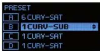
PRESET
Menu item for selecting loudspeaker presets for speakers from the LD CURV series. For example, select the preset 6 CURV-SATon the Smart Link® adapter for the appropriate channel if you wish to connect 6 x CURV 500 array satellites; select the preset 1 CURV SUB if you want to connect the CURV 500 installation-subwoofer (note: select the preset that corresponds with the number of satellites per SmartLink® adapter). Press the rotary MENUdial to access the device settings selection menu and then turn the dial to select the menu item PRESET (bright background). Now press the dial and then turn it to select the desired channel for the preset. Press the dial again and then turn it to select the desired preset. Confirm your selection by pressing the dial. Repeat this procedure to configure presets for the other channels. To return to the main display, turn the dial to select the menu item PRESET EXIT and confirm by pressing the dial. To return to the main display, turn the dial to select the menu item EXIT (light background) and confirm by pressing the dial. Folloing approximately 10 seconds of no input, the main display will appear automatically.


DEVICE CONFIGURATION (SETUP)
Menu item for editing device configuration, reading device firmware, resetting the device and managing global presets. Press the rotary MENU dial to access the selection menu for device settings and turn the dial to select the menu item SETUP (bright background). Confirm by pressing the dial.

This will take you to the sub-menu with the following menu items (turn the MENU dial to select, then confirm by pressing MENU):
| SETUP | |
| FIRMWARE The device firmware version is displayed in the top line of the display. | |
| NAME | Configure individual amplifier name (8 digits):Press the MENU dial -> Turn the MENU dial to select 1 to 8 -> Press MENU -> Rotate MENU to select letters, numbers, or characters -> Press MENU -> To exit, rotate MENU dial clockwise to arrow icon -> Press MENU. |
| PINON / OFF / EDIT | Activate automatic locking of controls to prevent accidental and unauthorisedoperation (except MASTER VOLUME, if enabled):Press MENU twice -> Rotate MENU to ON -> Press MENU -> To exit, rotate MENU to arrow symbol -> Press MENU |
| Deactivate automatic locking:Enter PIN to unlock menu (4-digit PIN factory setting: 1234) -> Rotate MENU to SETUP -> Press MENU -> Rotate MENU to PIN -> Press MENU twice -> Rotate MENU to OFF Press MENU -> To exit, rotate MENU to arrow symbol -> Press MENU | |
| Set personal PIN:Press MENU twice -> Rotate MENU to EDIT Press MENU -> Rotate MENU to select 0 - 9 for first digit -> Press MENU -> Rotate MENU to select 0 - 9 for second digit -> Press MENU etc. In the event of the PIN becoming lost, it can be reset to the factory setting (1234) by using the PC software and USB interface (downloadable from the product page at WWW.LD-SYSTEMS.COM). | |
| DELAY UNITMETRES / FEET | Configuring unit of measurement for channel delay METRES/FEET:Press MENU -> Rotate MENU to select METERSor FEET -> Press MENU -> To exit, rotate MENU to arrow symbol -> Press MENU |
| DELAY TEMP | Configuring distance calculation based on air temperature (sound speed is dependent upon air temperature):Press MENU twice -> Rotate MENU to select temperature from 0^ to 40^ -> Press MENU -> To exit, rotate MENU to arrow symbol -> Press MENU |
| CONNECT GNDYES / NO | Floating switching for disconnecting the signal ground from equipment grounding(to prevent ground loops):Press MENU twice -> Rotate MENU to YES for ground connection / NO for ground lift -> Press MENU -> To exit, rotate MENU to arrow symbol -> Press MENU |
| FACTORY SETTINGNO / YES | Reset to factory settings (e.g. resetting PIN to 1234 and OFF):Press MENU -> Rotate MENU to NO = do not reset device / YES = reset device -> press MENU |
| GLOBAL PRESET | Save all settings except amplifier name and PIN in global presets(16 internal memory slots):Press MENU -> Rotate MENU to SAVE PRESET -> Press MENU -> Rotate MENU to desired memory slot -> Press MENU -> Configure preset name: Rotate MENU to select digit (9 digits) -> Press MENU -> Rotate MENU to select letter, number or character -> Press MENU etc. -> Rotate MENU to YES -> Press MENU -> Rotate MENU to EXIT to go back -> Press MENU -> To exit, rotate MENU to EXIT -> Press MENU |
| Loading a global preset from internal memory:Press MENU -> Rotate MENU to LOAD PRESET -> Press MENU -> Rotate MENU to required preset -> Press MENU -> Rotate MENU to YES -> Press MENU -> Rotate MENU to EXIT to go back -> Press MENU -> To exit, rotate MENU to EXIT -> Press MENU | |
| SCREENSAVERON / OFF | Activate minimal display and reduced brightness (automatic activation after 5 minutes without input, display of channel and audio level):Press MENU 2x -> rotate MENU to ON for activated screensaver / OFF for deactivated screensaver -> press MENU -> to exit rotate MENU to arrow symbol -> press MENU |
| EXIT SETUP | To exit the setup-menu, rotate the MENU dial to EXIT SETUP and confirm by pressing MENU |
EXIT
To exit the selection menu and show the main display, turn the MENU dial to EXIT (light background) and confirm by pressing the MENU dial.

To set up a 70 V installation with the CURV 500 I AMP and CURV 500 satellites you require the LD Systems SmartLink adapter for 70 V applications LDCURV500SLAT (available in black and white, please note the instructions in the user manual for the LDCURV500SLAT); if you wish to use the speakON-compatible speaker output of the CURV 500 I AMP you require speaker cables with specially configured speakON-compatible plugs, since two amplifier channels can be connected simultaneously in bridge mode in conjunction with the relevant speaker preset. As an alternative to speakON-compatible plugs, you can use terminal block connectors (supplied, for configurations see diagram CONFIGURATION OF SPEAKER OUTPUTS or label on the amplifier, recommended for speaker cables 2 x 1.5 mm²). Select the preset corresponding to the number of satellites per SmartLink adapter as described under PRESET, then connect the CURV 500 I AMP and the CURV 500 SLAT SmartLink adapter. It is advisable not to combine SmartLink adapters with differing numbers of satellites due to the different preset settings. The maximum number of SmartLink adapters connected per bridge channel is derived from the number of CURV 500 satellites per SmartLink adapter.
Examples:
1 CURV 500 satellite per SmartLink adapter 70 V = maximum of 24 SmartLink adapters (24 x 20 W = 480 W max.)
Speaker preset 1xC500-70V


2 CURV 500 satellites per SmartLink adapter 70 V = maximum of 12 SmartLink adapters (12 x 40 W = 480 W max.)
Speaker preset 2xC500-70V


The speakON-compatible sockets and the terminal block connectors are wired in parallel. In bridge mode (BTL = Bridge Tied Load) / 70 V operation, the speakON-compatible sockets B and D may NOT be assigned; this also applies to the minus pins of the terminal block connections. For signal control, please note that the input routing can be freely configured (see ROUTING). A combination of two bridged amplifier channels (bridge mode) for controlling 70 V SmartLink adapters and controlling, for example, two CURV 500 ISUB speakers is possible in normal mode (e.g. channel A/B bridge mode – channels C and D in normal mode). Select the appropriate speaker presets.

TECHNICAL DATA
| Model number: LDCURV500IAMP | |
| Product type: DSP controlled amplifier | |
| Type: 4-Channel | |
| Rated output power (1 kHz @ 2,7 Ohm): 4 x 240 W (depending on preset) | |
| Rated output power (1 kHz @ 4 Ohm): 4 x 240 W (depending on preset) | |
| Rated output power (1 kHz @ 8 Ohm): 4 x 120 W (depending on preset) | |
| Rated output power (1 kHz @ 16 Ohm): 4 x 60 W (depending on preset) | |
| Rated power output BTL / 70 V operation (Bridge Tied Load, 1 kHz @ 4 Ohm): | 2 x 480 W (depending on preset) |
| Output circuitry: Class D | |
| Frequency response +/-1 dB: 10 Hz - 22000 Hz (depending on preset) | |
| THD: < 0,01 % @ 1 kHz (depending on preset) | |
| Protection circuits: Over-current, soft-start, DC, thermal overload, short circuit, multiband limiter | |
| Controls: Push-turn-control | |
| Indicators: | OLED display |
| AD/DA converter sampling frequency: 48 kHz | |
| AD/DA converter resolution: | 24 Bit |
| Dynamic range: | 114 dB |
| Maximum delay / Channel: | 59 m/ 166 ms |
| Equalizer: | 10x parametric / channel |
| Line inputs: | 4 |
| Line input connectors: | XLR (symmetrical), screw-/plug-in-terminals |
| Loudspeaker outputs: | 4 |
| Speaker output connections: Speakon compatible, screw-/plug-in-terminals | |
| Ground Lift: | Yes, GUI integrated |
| Cooling: | Temperature controlled low-noise fan, noiseless in idle mode |
| Operating voltage: | 100 - 240 V AC / 50 - 60 Hz |
| Fuse: 110 - 120 V AC: T10AL / 250 V | 220 - 240 V AC: T5AL / 250 V |
| Power consumption @ full load: | 1100 W |
| Ambient temperature (in operation): | 0 °C - 35 °C |
| Relative humidity (in operation): | <80 % (non condensing) |
| Width: | 482 mm |
| Height: | 44 mm |
| Depth: | 420 mm |
| Weight: | 6.8 kg |
| Features: | 4-channel DSP controlled, Purpose-designed for CURV500 installations, Smart 19" / 1U housing, Each channel can drive up to six CURV500 satellites or one CURV500ISUB subwoofer, Single push encoder operation, High contrast OLED display, Temperature controlled low-noise fan, High efficiency switch mode power supply (PFC) |
MANUFACTURER'S DECLARATIONS
MANUFACTURER'S WARRANTY & LIMITATIONS OF LIABILITY
You can find our current warranty conditions and limitations of liability at: https://cdn-shop.adamhall.com/media/pdf/MANUFACTURERS-DECLARATIONS_LD_SYSTEMS.pdf. To request warranty service for a product, please contact Adam Hall GmbH, Adam-Hall-Str. 1, 61267 Neu Anspach / Email: Info@adamhall.com / +49 (0)6081 / 9419-0.

CORRECT DISPOSAL OF THIS PRODUCT
(valid in the European Union and other European countries with a differentiated waste collection system)
This symbol on the product, or on its documents indicates that the device may not be treated as household waste. This is to avoid environmental damage or personal injury due to uncontrolled waste disposal. Please dispose of this product separately from other waste and have it recycled to promote sustainable economic activity. Household users should contact either the retailer where they purchased this product, or their local government office, for details on where and how they can recycle this item in an environmentally friendly manner. Business users should contact their supplier and check the terms and conditions of the purchase contract. This product should not be mixed with other commercial waste for disposal.
CE Compliance
Adam Hall GmbH states that this product meets the following guidelines (where applicable):
R&TTE (1999/5/EC) or RED (2014/53/EU) from June 2017
Low voltage directive (2014/35/EU)
EMV directive (2014/30/EU)
RoHS (2011/65/EU)
The complete declaration of conformity can be found at www.adamhall.com.
Furthermore, you may also direct your enquiry to info@adamhall.com.
DEUTSCH
MASTER VOLUME
BRIDGE-MODUS / 70 V-BETRIEB
natural_image
Front view of a computer interface with multiple ports and a small inset diagram showing three connected components (no text or symbols visible)

1x LDCURV500SAT
LDCURV500SLAT

2 x CURV 500 Satellit pro SmartLink Adapter 70V = Menge maximal 12 SmartLink Adapter (12 x 40W = 480W max.)

natural_image
Close-up of a dark textured fabric with horizontal bands and a small 'LD' label at the bottom (no other text or symbols)
natural_image
Close-up of a dark textured fabric with a white 'LD' label at the bottom (no other text or symbols)2 X LDCURV500SAT
LDCURV500SLAT


APPAREILS RELIÉS AU SECTEUR
6 OUTPUT CH A - CH D (compatible speakON)
7 OUTPUT CH A - CH D (bornier à vis)
9 INPUT IN 1 - 4 (bornier à vis)
MASTER VOLUME
DELAY
POLARITY
PRESET
MODE BRIDGE / FONCTIONNEMENT 70 V
CARACTÉRISTIQUES TECHNIQUES
(Bridge Tied Load, 1 kHz @ 4 ohms):
(Valid in the European Union and other European countries with waste separation)


DELAY
ROUTING
ECUALIZADOR
POLARITY
PRESET

MASTER VOLUME
DELAY
POLARITY
LINK SETT
PRESET
KONFIGURACJA URZĄDZENIA (SETUP)
TRYB MOSTU/ ZASILANIA 70 V


MASTER VOLUME
POLARITY
PRESET
BRIDGE MODE/70V


DISPOSIZIONE USCITE ALTOPARLANTE

DATI TECNICI

主音量
延迟
极性
信道连接
预设
设备设置 (SETUP)
橋接模式 / 70 V 設備

技术参数

主音量(MASTER VOLUME)
延遲 (DELAY)
路由(ROUTING)
等化器(EQUALIZER)
極性 (POLARITY)
預設 (PRESET)
桥接模式/70V运行模式


技術規格
型號:LDCURV500IAMP


- DEUTSCH
- SAFETY INFORMATION
- FOR EQUIPMENT THAT CONNECTS TO THE POWER MAINS
- CAUTION:
- CAUTION! HIGH VOLUMES IN AUDIO PRODUCTS!
- INTRODUCTION
- DISPLAY
- MENU
- VENTILATION GRILL
- POWER SOCKET AND FUSE HOLDER
- POWER ON / OFF
- OUTPUT CH A - CH D (speakON-compatible)
- OUTPUT CH A - CH D (screw connection)
- INPUTS 1 - 4 (3-pin XLR)
- INPUTS 1 - 4 (terminal block connections)
- DATA USB
- HOUSING FAN
- OPERATION
- DISPLAY MAIN DISPLAY
- CHANNEL VOLUME
- MASTER VOLUME
- DELAY
- ROUTING
- EQUALIZER
- POLARITY
- LINK SETT
- PRESET
- DEVICE CONFIGURATION (SETUP)
- EXIT
- Examples:
- MANUFACTURER'S DECLARATIONS
- MANUFACTURER'S WARRANTY & LIMITATIONS OF LIABILITY
- CORRECT DISPOSAL OF THIS PRODUCT
- CE Compliance
- BRIDGE-MODUS / 70 V-BETRIEB
- APPAREILS RELIÉS AU SECTEUR
- OUTPUT CH A - CH D (compatible speakON)
- OUTPUT CH A - CH D (bornier à vis)
- INPUT IN 1 - 4 (bornier à vis)
- MODE BRIDGE / FONCTIONNEMENT 70 V
- CARACTÉRISTIQUES TECHNIQUES
- ECUALIZADOR
- KONFIGURACJA URZĄDZENIA (SETUP)
- TRYB MOSTU/ ZASILANIA 70 V
- BRIDGE MODE/70V
- DISPOSIZIONE USCITE ALTOPARLANTE
- 主音量
- 延迟
- 极性
- 信道连接
- 预设
- 设备设置 (SETUP)
- 橋接模式 / 70 V 設備
- 主音量(MASTER VOLUME)
- 延遲 (DELAY)
- 路由(ROUTING)
- 等化器(EQUALIZER)
- 極性 (POLARITY)
- 預設 (PRESET)
- 桥接模式/70V运行模式
- 技術規格
Brand : LD Systems
Model : CURV 500 I AMP
Category : Receiver