
MAILA SPA - Receiver LD Systems - Free user manual and instructions
Find the device manual for free MAILA SPA LD Systems in PDF.
| Product Type | Amplification module for MAILA satellites |
| Brand | LD Systems |
| Model | MAILA SPA |
| Category | Receiver |
| Dimensions (W x H x D) | 205 x 282 x 226 mm |
| Weight | 7.45 kg |
| Power Supply | 100-240 V AC, 50-60 Hz |
| Max Power Consumption | 400 W |
| Amplifier | Class D, 1250 W RMS |
| DSP Processing | 24 bit, 48 kHz |
| Bluetooth | Version 4.2 |
| Line Inputs | 1 x locking female XLR |
| Line Outputs | 1 x male XLR (THRU) |
| Wireless Connectivity | SmartLink+® for satellites, LogoLink® for app control |
| Display and Controls | LC display with rotary push encoder |
| LED Indicators | PWR (white), SIG (white), LIMIT (yellow), PROT (red) |
| Housing Material | Unibody die-cast aluminum with powder coating |
| Mounting | 2 x M10, MAILA yoke, EasyMount+® |
| Operating Temperature | 0 to 40 °C |
| Relative Humidity | <80%, non-condensing |
| Package Contents | 1x SPA module, 1x power cord, 1x M10 lifting ring, user manual |
| Care and Cleaning | Clean surfaces with a damp cloth; do not use abrasive products |
| Safety | Do not open the device; follow safety and mounting instructions |
| Warranty and Compliance | CE, WEEE, manufacturer's warranty according to Adam Hall terms |
Frequently Asked Questions - MAILA SPA LD Systems
User questions about MAILA SPA LD Systems
0 question about this device. Answer the ones you know or ask your own.
Ask a new question about this device
Download the instructions for your Receiver in PDF format for free! Find your manual MAILA SPA - LD Systems and take your electronic device back in hand. On this page are published all the documents necessary for the use of your device. MAILA SPA by LD Systems.
USER MANUAL MAILA SPA LD Systems
Firmware Version 1.0.2 and later
CONTENTS / INHALTSVERZEICHNIS / CONTENU / CONTENIDO / TRESC / CONTENO
ENGLISH
ABOUT THIS MANUAL 3
INTENDED USE 3
EXPLANATIONS OF TERMS AND SYMBOLS 3
SAFETY INSTRUCTIONS 4
SCOPE OF DELIVERY 7
PROPERTIES 8
MAILA APP (iPadOS) 8
CCONSTRUCTION AND TRANSPORT ASSEMBLY 8
CONNECTIONS, CONTROLS AND DISPLAY ELEMENTS 10
SERVICE 12
MAILA APP 17
FIRMAWARE UPDATE 17
INDICATION-LED 17
OPTIONAL ACCESSORIES 18
CARE, MAINTENANCE AND REPAIR 18
DIMENSIONS 19
SPECIFICATIONS 20
DISPOSAL 21
MANUFACTURER DECLARATION 21
DEUTSCH
ACCESSIONS OPTIONNELS 57
ENTRETIEN, MAINTENANCE ET RÉPARATION 57
DIMENSIONS 58
This device was developed and manufactured under high quality requirements to ensure many years of trouble-free operation. This is what LD Systems stands for with its name and many years of experience as a manufacturer of high-quality audio products. Please read these operating instructions carefully so that you can quickly and optimally use your new LD Systems product.
You can find more information about LD SYSTEMS on our website www.LD SYSTEMS.COM
ABOUT THIS MANUAL
- Read the safety instructions and the entire manual carefully before starting up.
- Observe the warnings on the device and in the operating instructions.
- Always keep the operating instructions within reach.
- If you sell or pass on the device, be sure to also pass on these operating instructions, as they are an integral part of the product.
INTENDED USE
The product is a device for professional audio installation!
The product has been developed for professional use in the field of audio installation and is not suitable for use in households!
Furthermore, this product is only intended for qualified users with specialist knowledge of dealing with audio installations!
Use of the product outside of the specified technical data and operating conditions is considered improper use!
Liability for damage and third-party damage to persons and property due to improper use is excluded! The product is not suitable for:
- People (including children) with reduced physical, sensory or mental abilities or lack of experience and knowledge.
- Children (Children must be instructed not to play with the device).
EXPLANATIONS OF TERMS AND SYMBOLS
- DANGER: The word DANGER, possibly in combination with a symbol, refers to directly dangerous situations or conditions for life and limb.
- WARNING: The word WARNING, possibly in combination with a symbol, refers to potentially dangerous situations or states of life and limb.
- ATTENTION: The word CAUTION, possibly in combination with a symbol, refers to situations or conditions that can lead to injuries.
- DANGER: The word ATTENTION, possibly in combination with a symbol, refers to situations or states that can lead to damage to property and/or the environment.
This symbol indicates hazards that can cause an electric shock.

This symbol indicates danger spots or dangerous situations.
This symbol indicates danger from hot surfaces.
This symbol indicates danger from high volumes.

This symbol indicates supplementary information on the operation of the product.

This symbol denotes a device that does not contain any user-serviceable parts.
SAFETY INSTRUCTIONS
DANGER:
- Do not open or modify the device.
- If your device is no longer working properly, liquids or objects have gotten inside the device, or the device has been damaged in any other way, switch it off immediately and disconnect it from the power supply. This device may only be repaired by authorized specialist personnel.
- For devices of protection class 1, the protective conductor must be connected correctly. Never interrupt the protective conductor. Protection class 2 devices do not have a protective conductor.
- Ensure that live cables are not kinked or otherwise mechanically damaged.
- Never bypass the device fuse.
WARNING:
- The device must not be put into operation if it shows obvious signs of damage.
- The device may only be installed in a voltage-free state.
- If the power cord of the device is damaged, the device must not be put into operation.
- Permanently connected mains cables may only be replaced by a qualified person.
DANGER:
- Do not operate the device if it has been exposed to severe temperature fluctuations (e.g. after transport). Humidity and condensation could damage the device. Do not switch on the device until it has reached the ambient temperature.
- Make sure that the voltage and frequency of the mains supply correspond to the values indicated on the device. If the device has a voltage selector switch, do not connect the device until this is set correctly. Only use suitable power cords.
- To disconnect the device from the mains at all poles, it is not enough to press the on/off switch on the device.
- Ensure that the fuse used corresponds to the type printed on the device.
- Make sure that appropriate measures against overvoltage (e.g. lightning) have been taken.
- Note the specified maximum output current on devices with a power out connection. Make sure that the total power consumption of all connected devices does not exceed the specified value.
- Only replace pluggable mains cables with original cables.

DANGER:
- Danger of suffocation! Plastic bags and small parts must be kept out of the reach of people (including children) with reduced physical, sensory or mental abilities.
- Danger from falling! Make sure the device is installed securely and cannot fall. Only use suitable tripods or attachments (especially for fixed installations). Make sure accessories are properly installed and secured. Make sure that the applicable safety regulations are observed.

WARNING:
- Only use the device in the manner intended.
- Only operate the device with the accessories recommended and intended by the manufacturer.
- During installation, observe the safety regulations applicable in your country.
- After connecting the device, check all cable routes to avoid damage or accidents, e.g. B. to avoid tripping hazards.
- Be sure to observe the specified minimum distance to normally flammable materials! Unless this is explicitly stated, the minimum distance is 0.3m .

ATTENTION:
- There is a risk of jamming with moving components such as mounting brackets or other moving components.
- In the case of devices with motor-driven components, there is a risk of injury from the movement of the device. Sudden device movements can lead to startle reactions.

DANGER:
- Do not install or operate the device near radiators, heat registers, stoves or other heat sources. Make sure that the device is always installed in such a way that it is sufficiently cooled and cannot overheat.
- Do not place any sources of ignition such as burning candles near the device.
- Ventilation openings must not be covered and fans must not be blocked.
- Use the original packaging or packaging provided by the manufacturer for transport.
- Avoid shock or shock to the device.
- Observe the IP protection class and the environmental conditions such as temperature and humidity according to the specification.
- Devices can be continuously developed. In the event of deviating information on operating conditions, performance or other device properties between the operating instructions and the device labeling, the information on the device always has priority.
- The device is not suitable for tropical climate zones and for operation above 2000m above sea level.

ATTENTION:
Connecting signal cables can result in significant noise interference. Make sure that devices connected to the output are muted during plugging. Otherwise, noise levels can cause damage.
ATTENTION HIGH VOLUMES WITH AUDIO PRODUCTS!
This device is intended for professional use.
The commercial operation of this device is subject to the applicable national regulations and guidelines for accident prevention.
Hearing damage due to high volumes and continuous exposure: The use of this product can generate high sound pressure levels (SPL) which can cause hearing damage. Avoid exposure to high volumes.

SIGNAL TRANSMISSION VIA RADIO (e.g. W-DMX or audio radio systems, Bluetooth):
The quality and performance of wireless signal transmissions generally depends on the environmental conditions.
Influence on the range and signal stability, for example:
- Shielding (e.g. masonry, metal structures, water)
High radio traffic (e.g. strong W-LAN networks) - interference
- Electromagnetic radiation (e.g. LED video walls, dimmers)
All range specifications refer to free field use with visual contact without interference!
The operation of transmitters is subject to official regulations. These can vary from region to region and must be checked by the operator before commissioning (e.g. radio frequency and transmission power).

WARNING:
Devices with wireless signal transmission are not suitable for operation in sensitive areas in which radio operation can lead to possible interactions. These include, for example:
- Hospitals, health centers or other healthcare facilities that perform patient treatments with specialized staff and equipment.
Class I, II and III hazardous areas - restricted areas
· military facilities
airplanes or vehicles - Areas where cell phone use is prohibited

NOTES FOR PORTABLE INDOOR DEVICES
- Temporary operation! Event equipment is basically only designed for temporary operation.
- Continuous operation or permanent installation can lead to impairment of the function and premature aging of the devices.
SCOPE OF DELIVERY
Remove the product from the packaging and remove all packaging material. Check the completeness and integrity of the delivery and please notify your distributor immediately after purchase if the delivery is not complete or damaged. The product comes with:
- 1x LD MAILA SPA amplifier module for MAILA satellites
- 1x Power cord
- 1x M10 eyebolt
- Operating instructions
PROPERTIES
MAILA SPA is the only MAILA module without integrated loudspeakers - and yet an integral part of the MAILA concept. Its versatility can already be guessed at when looking at the range of MAILA sets: The MAILA SPA amplifier module is used both in the smallest MAILA-S ground stack set and in the large MAILA XL version with flown arrays.
MAILA SPA is an amplifier module in an elegant unibody aluminium design with integrated 1.25 kW power amplifier with SysCore® DSP for controlling up to eight MAILA SAT satellites. Via the SmartLink+® system, the satellites can be easily plugged in and wirelessly supplied with the audio signal. In addition, SmartLink+® enables the independent determination of the installed satellites for either automatic or manual DSP processing. As with the MAILA COL column module, MAILA SPA allows users to implement ground stack configurations with a distance pole (supplied in the MAILA S Set) as well as flown systems with the EasyMount+® mounting adapter.
With LogoLink®, LD Systems maila has added another innovation. Via the free MAILA app (iPadOS), every MAILA system can be adapted quickly, easily and in detail and wirelessly supplied with software updates. Once connected, the app automatically detects the existing MAILA components and enables the system to be optimally set up in advance and during an event. The highlight: The required wireless antennas are invisibly integrated into the LD logo of the MAILA SPA.

MAILA APP (iPadOS)
The MAILA app for iPadOS is available free of charge in the App Store.

CCONSTRUCTION AND TRANSPORT ASSEMBLY

DANGER:
Always place the speaker system in a suitable place on a sufficiently load-bearing, flat and horizontal surface. Make sure that the speaker system cannot fall off the edge of a stage (e.g. due to vibration).

DANGER:
Overhead assembly requires extensive experience, including calculating workload limits, installation material used, and regular safety review of all installation materials and equipment. If you do not have these qualifications, do not try to do an installation yourself, but use the help of professional companies. There is a risk that incorrectly assembled and secured devices will come loose and fall down. As a result, people can be seriously injured or killed.
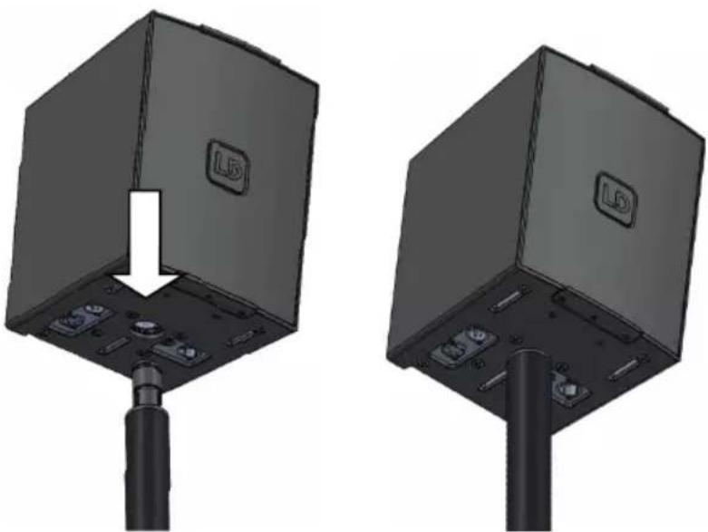
Mount the amplifier module on the distance pole: Plug the amplifier module in the desired beam direction from above onto the LD MAILA DB distance pole already mounted on the subwoofer. Unintentional twisting of the amplifier module is prevented by a tongue and groove principle.
Use the optionally available EasyMount+ flying bracket for truss mounting (item number LDMAILATMB).
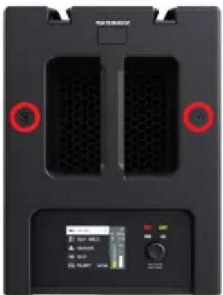
There are two M10 threads on the back of the MAILA SPA amplifier module (see markings). Use one of them to secure the amplifier module when mounting the crossbar. Remove the inserted blind screw using a suitable tool. An M10 eyebolt is included in the scope of delivery of the MAILA SPA. Screw the eyebolt into the now free thread and make sure it is firmly fixed. Use a suitable safety rope to secure the amplifier module and also take into account the total weight of the satellite speakers mounted on the amplifier module.
NOTE
The satellites do not need to be secured by a safety cable as the SmartLink+ connection meets the criteria for inherent safety.
However, if desired, the satellite speakers can be secured to the amplifier module using the second M10 thread.
CONNECTIONS, CONTROLS AND DISPLAY ELEMENTS
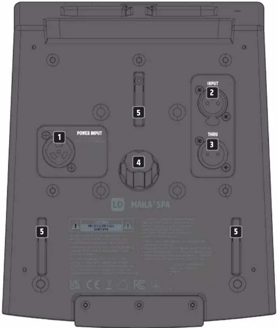

POWER INPUT
PowerCON TRUE1 power input jack. A suitable power cord is included
2 INPUT
Balanced line input with lockable, female 3-pole XLR socket.
3 THRU
Balanced line output for forwarding the line input signal (male 3-pole XLR socket).
4 TRIPOD FLANGE
Tripod flange for the distance pole LD MAILA DB.
5 HOLDING BUSHES
Holding sockets for the EasyMount+ flight bracket LD MAILA TMB.
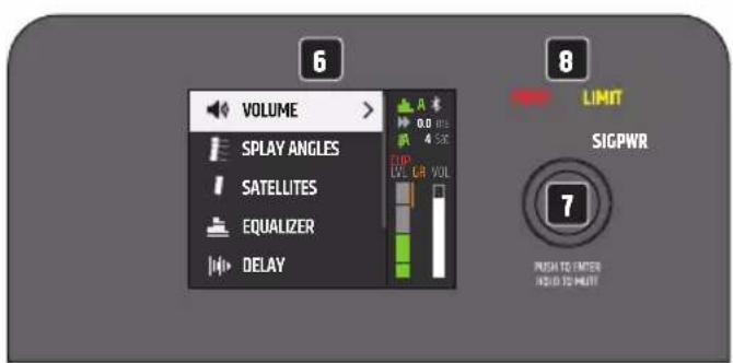
6 LC-DISPLAY
Multifunctional graphic LC display with lighting.
PUSH TO ENTER / HOLD TO MUTE
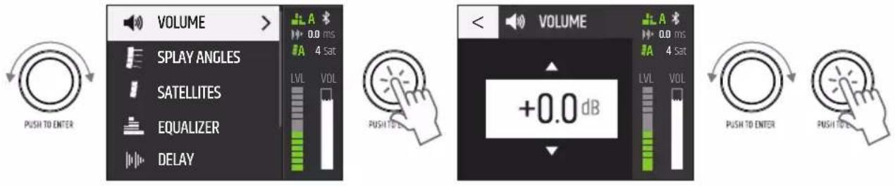
Rotary push encoder for navigating the main menu and submenus and adjusting system settings. Select the individual menu items in the main menu and in the submenus by rotating the encoder and confirm the selection by pressing the encoder. Change a numerical value or status in a menu item by rotating the encoder and confirm the change by pressing the encoder. To move up one level in the menu structure, select the arrow symbol < and confirm the selection.
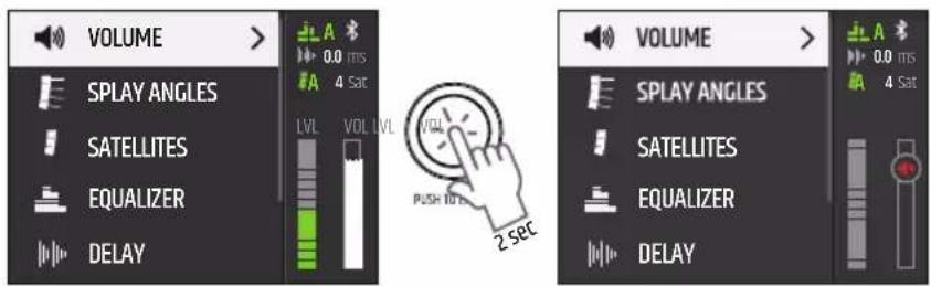
Press the encoder for about 2 seconds to mute the amplifier module and again for about 2 seconds to unmute it.
8 LEDs TO INDICATE THE STATUS OF THE UNIT
PWR - (Power)
The PWR indicator lights up white when the unit is correctly connected to the mains and switched on.
SIG - (Signal)
The SIG indicator lights up white when an audio signal is present in the unit.
LIMIT - (Limiter)
The LIMIT indicator lights up yellow when the amplifier module is operated in the upper limit range. Brief illumination of the LED is not critical. To protect the system, any excessive signal level is lowered smoothly by the integrated limiter. The level reduction is shown graphically under GR in the display (Gain Reduction). If the limiter LED remains lit for a longer period, or permanently, reduce the volume level.
PROT - (Protect)
The PROT indicator lights up red if the amplifier module is overloaded or overheating. The amplifier module is automatically muted. After reaching normal operating conditions, the unit returns to the normal operating mode after a few minutes.
9 PUSH TO UNLOCK SAT
At the rear top of the amplifier module is the release button for releasing a mounted satellite speaker.
VENTS
To avoid damage to the device, do not cover the vents on the back and ensure that air can circulate unhindered.
SERVICE
HINTS
- When switching on, all settings, such as VOLUME and EQUALIZER, are loaded as they were before the speaker column was switched off. After a short time, the amplifier module is ready for operation.
- After about 30 seconds without any input by rotary-push encoder, the display system leaves lower levels in the menu structure and the main display with the VOLUME selection is automatically shown.
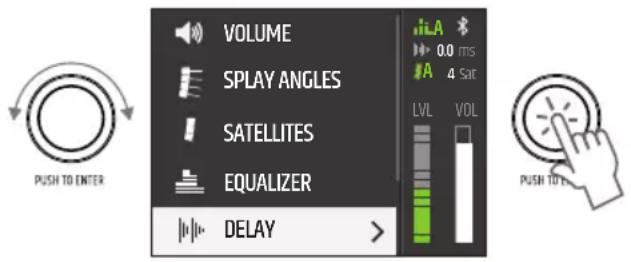
MAIN DISPLAY
In normal operation, the main display is activated, showing VOLUME with the current value, the set delay and the number of satellites used. The Bluetooth status, the volume level (LVL), the gain (VOL) and the status of the automatic equaliser (AUTO EQ) and the automatic satellite detection (AUTO DETECT) are displayed graphically. The level reduction by the integrated limiter is displayed under GR (Gain Reduction). If the red CLIP indicator lights up, this signals that the input stage is being operated above the distortion limit. Reduce the output level of the feed device (e.g. mixing console) until the CLIP indicator no longer lights up and the amplifier module plays back audio signals without distortion.
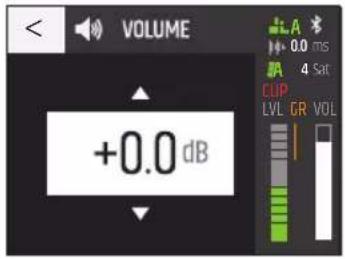
VOLUME
Adjust the level of the amplifier module by using the encoder directly from the main display, or select VOLUME from the main menu, confirm and then set the desired value from -40 dB to +10 dB.
Mute: Press the encoder for about 2 seconds to mute the amplifier module and again for about 2 seconds to unmute (at all menu levels).
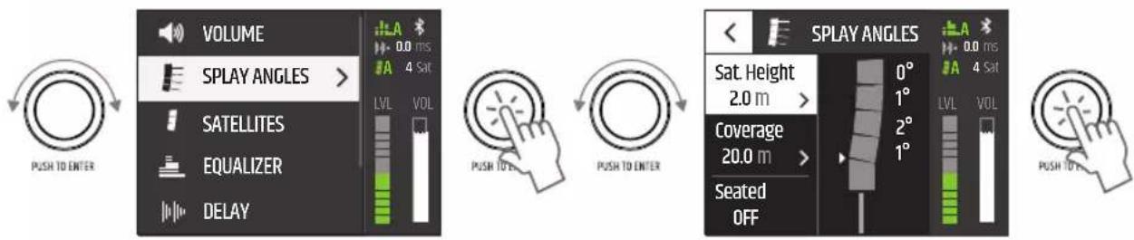
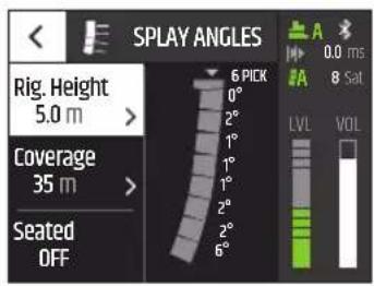
SPLAY ANGLES
Mounting on distance pole:

To enable the automatic calculation of the optimal spreading angles of the satellites, the rotation of the display must be set correctly.
ROTATION menu item, status: standing
The number of satellite speakers used is automatically detected by the module electronics if the status ON is set in the menu item SATELLITES under AUTO DETECT. Alternatively, enter the corresponding number of satellites manually under QUANTITY and deactivate the automatic detection (AUTO DETECT OFF). To enter the relevant data of the audience area and the height at the measuring point, select SPLAY ANGLES in the main menu, confirm, then select the corresponding sub menu item and confirm again. Select at Sat. Height the adequate value for the height of the bottom edge of the lowest satellite measured from the audience's location and the distance from the array system to the back row of the audience (Coverage) in metres. Under Seated, enter standing (Seated OFF) or seated audience (SeatedON). Now the optimal spreading angles for each satellite are automatically displayed. To exit the menu level, select the arrow symbol and confirm the selection. The spread angles are set manually on the satellite speakers. The correct setting of the indicated spreading angles is a prerequisite for the optimal sound distribution across the indicated listening area.
TRUSS MOUNTING:

In order to enable the automatic calculation of the optimal spreading angles of the satellites and the optimal suspension point of the EasyMount+ flight bar (for truss mounting), the rotation of the display display must be set correctly.
Menu item ROTATION, Status: flying
The number of satellite speakers used is automatically detected by the module electronics if the status ON is set in the menu item SATELLITES under AUTO DETECT. Alternatively, enter the corresponding number of satellites manually under QUANTITY and deactivate the automatic detection (AUTO DETECT OFF). To enter the relevant data of the audience area and the height at the measuring point, select SPLAY ANGLES in the main menu, confirm, then select the corresponding sub menu item and confirm again. Choose from Rig. Height the adequate value for the height of the top edge of the uppermost satellite measured from the audience's location and the distance from the array system to the back row of the audience (Coverage) in metres. Under Seated, enter standing (Seated OFF) or seated audience (SeatedON). Now the optimal spreading angles for each satellite are automatically displayed. To exit the menu level, select the arrow symbol and confirm the selection.
The spread angles are set manually on the satellite speakers. The correct setting of the indicated spreading angles is a prerequisite for the optimal sound distribution across the indicated listening area. The optimum hanging point is displayed under PICK.
SATELLITES
The number of satellite speakers used is automatically detected by the module electronics if the status ON is set in the menu item SATELLITES under AUTO DETECT. Alternatively, enter the corresponding number of satellites manually under QUANTITY and deactivate the automatic detection (AUTO DETECT OFF). AUTO EQ ON: An intelligent equaliser automatically equalises the system according to the number of satellites used and the specifications under Sat. or Rig. Height, Coverage and Seated. If automatic equalisation is not desired, it can be deactivated (AUTO EQ OFF). The AUTO EQ works independently of the fully parametric 10-band equaliser.
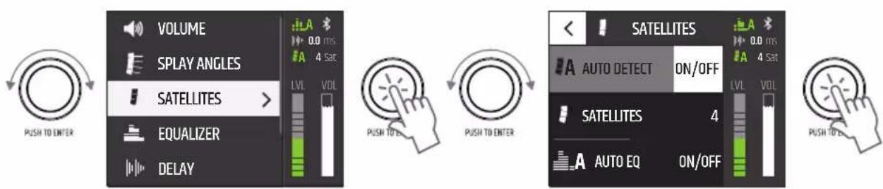
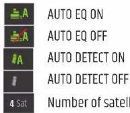
The statuses of the corresponding functions are shown in the display:
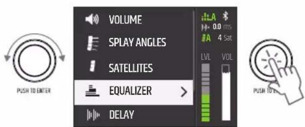
EQUALIZER
The integrated DSP (Digital Signal Processor) has a powerful 10-band fully parametric equaliser. Select EQUALIZER in the main menu and confirm the selection.
The functionality of the equalizer bands 1 and 10 can be set either as fully parametric or as low-shelf (band 1, LS) or hi-shelf (volume 10, HS).
| EQ ON / OFF | |||
| NO FREQ Q GAIN | |||
| 130 | -20000 0.1 | -10.0 / LS -20 +10 | |
| 230 | -20000 0.1 | -10.0 -20 +10 | |
| 330 | -20000 0.1 | -10.0 -20 +10 | |
| 430 | -20000 0.1 | -10.0 -20 +10 | |
| 530 | -20000 0.1 | -10.0 -20 +10 | |
| EQ ON / OFF | |||
| NO | FREQ Q GAIN | ||
| 6 | 30 - 20000 0.1 | -10.0 -20 | - +10 |
| 7 | 30 - 20000 0.1 | -10.0 -20 | - +10 |
| 8 | 30 - 20000 0.1 | -10.0 -20 | - +10 |
| 9 | 30 - 20000 0.1 | -10.0 -20 | - +10 |
| 10 | 30 - 20000 | 0.1 - 10.0 / HS | -20 - +10 |
To set the frequency in Hertz under FREQ, the Q-factor or the functionality of bands 1 and 10 under Q and the gain in dB under GAIN select the corresponding column in the desired equalizer band (NR 1 - 10), confirm, set the value as desired and confirm again. The selected value is displayed in white.
The EQ bands can be disabled individually by selecting and confirming the band number. Instead of a check mark icon, an X is now displayed and the values in the corresponding volume appear grayed out. To activate the tape, select and confirm again.
The entire equalizer can be disabled by selecting the EQ line confirming, then selecting OFF and confirming again. All values in the equalizer are now graved out. To activate the equalizer, select ON and confirm. To exit the menu level, select the arrow icon and confirm the selection.
DELAY
To delay the audio signal, select DELAY confirm, then select the desired submenu item and confirm again. The value or status can now be set as desired, confirm each entry.
| DELAY TIME x.x ms | ms/m/ft Set the delay time in the selected delay unit | |
| DELAY UNIT ms Delay unit milliseconds | ||
| m | Delay Unit Meter | |
| ft Delay Unit Foot | ||
| TEMPERATURE | x °C / °F | Set ambient temperature in the selected temperature unit |
| TEMP. UNIT | °C | Temperature unit Celsius |
| °F | Temperature unit Fahrenheit | |
To exit the menu level, select the arrow icon and confirm the selection.
POLARITY
To set the polarity of the audio signal, select POLARITY confirm, then select the desired status and confirm the selection.
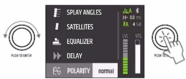
| POLARITY n | normal normal | al polarity |
| inverted inverted polarity | ||
ROTATION
To set the rotation of the display display, select ROTATION confirm, then select the desired status and confirm the selection.

In order to enable the automatic calculation of the optimal spreading angles of the satellites and the optimal suspension point of the EasyMount flight bracket (for truss mounting), the rotation of the display display must correspond to the mounting type.
- Mounting on distance pole: ROTATION standing
- Truss mounting (180° rotation): ROTATION flying
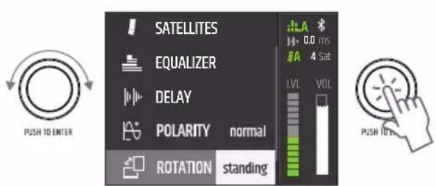
| ROTATION | standing | standing upright |
| flying Truss | assembly |
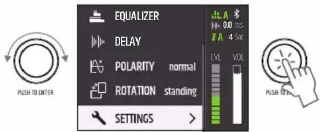
SETTINGS
To access the System Preferences menu, select SETTINGS and confirm the selection. Then select the desired submenu item and confirm the selection.
| PIN LOCK * * * | ← ① Enter PIN code to LOCK | Protect the amplifier module from accidental and unauthorised operation by activating the lock function. Enter a 4-digit PIN and confirm the entry. Access can now only be achieved after entering the PIN. Reset PIN: Press and hold the encoder when switching on (connect the unit to the mains). | |
| BLUETOOTH OFF | Bluetooth deactivated. | ||
| ON | Bluetooth activated. Access to the system via tablet App enabled. | ||
| DISPLAY Brightness Adjust the display brightness from 10% to 100%. | |||
| Screensaver active | Deactivation of the display illumination after approx. 1 minute without input via rotary-push encoder. | ||
| inactive Display lighting permanently on | |||
| FIRMWARE | System: | xxx Display of the system firmware. | |
| Wireless: | xxx.xxx Display of the firmware of the wireless module. | ||
| RESET | FACTORY DEFAULT RESET | Restore factory settings: Select RESET and confirm. | |
(the illustrations in the unit menu may vary slightly depending on the software version)
MAILA APP
Download the MAILA app, which is available free of charge in the App Store, onto your tablet and install it. Activate Bluetooth in the system settings of the active MAILA components. Also activate Bluetooth in the system settings of your tablet and start the MAILA app. The MAILA components with activated Bluetooth within range are now automatically displayed in the MAILA app after a short time.
FIRMWARE UPDATE
Check with the help of the MAILA app whether a new firmware is available for your device. Start the update procedure via MAILA App. Make sure that there is a stable wireless connection between the device and tablet and do not turn off the device or tablet before the update procedure is complete. Aborting the update procedure may cause the device to malfunction. The MAILA app for iPadOS is available free of charge in the App Store.
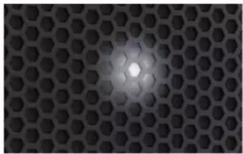
INDICATION-LED
The amplifier module has a white display LED on the front behind the front grille. This can be activated to easily identify the amplifier module with the help of the MAILA app. The MAILA app for iPadOS is available free of charge in the App Store.
OPTIONAL ACCESSORIES
LDMAILAFC1 (Flightcase for 4x SAT, 1x SPA, 1x distance pole)
LDMAILAFC3 (Flightcase for 8x SAT, 1x SPA, 1x EasyMount+)
LDMAILADB (distance pole)
LDMAILATMB (EasyMount+ flight bracket)
CARE, MAINTENANCE AND REPAIR
In order to ensure the proper functioning of the device in the long term, it must be regularly maintained and maintained if necessary. The need for care or maintenance depends on the intensity and environment of use. We generally recommend a visual inspection before each commissioning. Furthermore, we recommend every 500 operating hours, or in the case of lower intensity of use at the latest after one year, to carry out all the care measures mentioned below and applicable. In the case of defects that are due to inadequate care, there may be limitations of the warranty claims.
CARE (CAN BE CARRIED OUT BY THE USER)

WARNING! Before any maintenance measures, the power supply and, if possible, all device connections must be disconnected.

HINT! Improper care can lead to impairment of the device up to destruction.
- Housing surfaces must be cleaned with a clean, damp cloth. Care must be taken to ensure that no moisture can penetrate into the device.
- Air inlet and outlet openings must be regularly cleaned of dust and dirt. In the case of the use of compressed air, care must be taken to prevent damage to the device (e.g. fans must be blocked in this case).
- Cables and plug-in contacts must be cleaned regularly and cleaned of dust and dirt.
- In general, no cleaning agents or agents with a grinding effect may be used for care, otherwise the surface quality is to be expected to be impaired.
- Equipment must generally be stored dry and protected from dust and dirt.
MAINTENANCE AND REPAIR (ONLY BY QUALIFIED PERSONNEL)
DANGER! There are live components in the device. Even after disconnection of the mains connection, residual voltage may still be present in the device, e.g. due to charged capacitors

HINT! There are no modules in the device that can be serviced by the user.

HINT! Maintenance and repair measures may only be carried out by specialist personnel authorised by the manufacturer. If in doubt, contact the manufacturer.

HINT! Improperly performed maintenance work may affect the warranty claim.
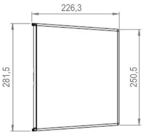
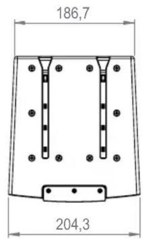
DIMENSIONS (mm)
SPECIFICATIONS
| Item number LDMAILASPA | |
| Product type MAILA Satellite Amplifier | |
| Type Powered | |
| Amplifier Class D | |
| System Power (RMS) 1250 W | |
| Protection features limiter, over-current, thermal overload | |
| Input impedance 20000 ohm(s) | |
| Controls Rotary/push encoder | |
| Indicators LC display, LED indicator, Limit, Power, Protect, Signal | |
| Line inputs 1 | |
| Line input connectors XLR | |
| Line outputs 1 | |
| Line output connectors XLR | |
| Speaker output connections SmartLink+® | |
| Wireless Connectivity | LogoLink® for App Control |
| Operating voltage | SMPS |
| Operating voltage | 100 - 240 V AC, 50 - 60 Hz |
| Power consumption (max.) | 400 W |
| Operating Temperature | 0 - 40 °C |
| Relative Humidity | < 80 %, not condensing |
| Housing material | Die-cast aluminium unibody |
| Cabinet surface | Powder-coated |
| Mounting | 2 x M10, 25mm MAILA Flange, EasyMount+® |
| Handles | 1 |
| Width | 205 mm |
| Height | 282 mm |
| Depth | 226 mm |
| Weight | 7,45 kg |
| DSP Characteristic | |
| Bit depth AD/DA converter | 24-bit |
| Sampling frequency | 48 kHz |
| Bluetooth | |
| Bluetooth version | 4.2 |
| Bluetooth transmission power | 9 dBm |
| Bluetooth frequency range | 2402 - 2480 MHz |
DISPOSAL

Packaging:
- Packaging can be fed into the recycling cycle via the usual disposal routes.
- Please separate the packaging in accordance with the disposal laws and recyclable material regulations in your country.
Device:
- This device is subject to the European Directive for Waste Electrical and Electronic Equipment in the current version. WEEE Directive Waste Electrical and Electronic Equipment. Old appliances and batteries do not belong in the household waste. The old equipment or batteries must be disposed of via an approved disposal company or a municipal disposal facility. Please note applicable regulations in your country!
- Observe all disposal laws applicable in your country.
- As a private customer, you will receive information on environmentally friendly disposal options from the dealer from whom the product was purchased or from the relevant regional authorities.

Batteries and rechargeable batteries:
- Batteries and rechargeable batteries do not belong in the household waste. Batteries and accumulators must be disposed of via an approved disposal company or a municipal disposal facility.
- Observe all disposal laws and regulations applicable in your country.
- As a private customer, you will receive information on environmentally friendly disposal options from the dealer from whom the product was purchased or from the relevant regional authorities.
- Devices with batteries or rechargeable batteries that cannot be removed by the user must be handed in at a collection point for electrical appliances.
MANUFACTURER DECLARATION
MANUFACTURER'S WARRANTY & LIMITATION OF LIABILITY
Adam Hall GmbH, Adam-Hall-Str.1, D-61267 Neu Anspach / Email Info@adamhall.com / +49 (0)6081 / 9419-0. For our current warranty terms and limitation of liability see: https://cdn-shop.adamhall.com/media/pdf/MANUFACTURERS-DECLARATIONS_LD_SYSTEMS.pdf. In the event of service, please contact your sales partner.
UKCA- CONFORMITY
Hereby, Adam Hall Ltd. declares that this product meets the following guidelines (where applicable)
Electrical Equipment (Safety) Regulations 2016
Electromagnetic Compatibility Regulations 2016 (SI 2016/1091)
The Restriction of the Use of Certain Hazardous Substances in Electrical and Electronic Equipment Regulation 2012 (SI 2012/3032)
Radio Equipment Regulations 2017 (SI 2016/2015)
UKCA-DECLARATION OF CONFORMITY
Products that are subject to Electrical Equipment(Safety)Regulation 2016, EMC Regulation 2016 or RoHS Regulation can be requested at info@adamhall.com. Products that are subject to the Radio Equipments Regulations 2017 (SI2017/1206) can be downloaded from www.adamhall.com/compliance/
FCC STATEMENT
- This device complies with Part 15 of the FCC Rules. Operation is subject to the following two conditions:
(1) This device may not cause harmful interference, and
(2) This device must accept any interference received, including interference that may cause undesired operation.
- Changes or modifications not expressly approved by the party responsible for compliance could void the user's authority to operate the equipment.
RADIATION EXPOSURE STATEMENT
This equipment complies with FCC radiation exposure limits set forth for an uncontrolled environment. This equipment should be installed and operated with minimum distance 20cm between the radiator & your body.
NOTE: This equipment has been tested and found to comply with the limits for a Class B digital device, pursuant to Part 15 of the FCC Rules. These limits are designed to provide reasonable protection against harmful interference in a residential installation. This equipment generates, uses and can radiate radio frequency energy and, if not installed and used in accordance with the instructions, may cause harmful interference to radio communications. However, there is no guarantee that interference will not occur in a particular installation. If this equipment does cause harmful interference to radio or television reception, which can be determined by turning the equipment off and on, the user is encouraged to try to correct the interference by one or more of the following measures:
- Reorient or relocate the receiving antenna.
- Increase the separation between the equipment and receiver.
- Connect the equipment into an outlet on a circuit different from that to which the receiver is connected.
- Consult the dealer or an experienced radio/TV technician for help.
EU DECLARATION OF CONFORMITY
Adam Hall GmbH hereby declares that this radio system type complies with Directive 2014/53/EU. The full text of the EU declaration of conformity is under the following Internet address available: www.adamhall.com/compliance/
DEUTSCH
PUSH TO ENTER / HOLD TO MUTE
9 PUSH TO UNLOCK SAT
Menüpunkt ROTATION, Status: flying
ArticleNumber LDMAILASPA
Sampling-Frequency 48 kHz
Bluetooth
Bluetooth-Version 4.2
9 PUSH TO UNLOCK SAT
ACCESSIONS OPTIONNELS
PUSH TO ENTER / HOLD TO MUTE
https://cdn-shop.adamhall.com/media/pdf/MANUFACTURERS-DECLARATIONS_LD_SYSTEMS.pdf.
Adam Hall GmbH declares that this product is the best available for use in the market.
9 PUSH TO UNLOCK SAT
PUSH TO ENTER / HOLD TO MUTE
9 PUSH TO UNLOCK SAT
Adam Hall Ltd. | The Seedbed Business Centre | SS3 9QY Essex | UK


- CONTENTS / INHALTSVERZEICHNIS / CONTENU / CONTENIDO / TRESC / CONTENO
- ENGLISH
- DEUTSCH
- ABOUT THIS MANUAL
- INTENDED USE
- EXPLANATIONS OF TERMS AND SYMBOLS
- SAFETY INSTRUCTIONS
- DANGER:
- WARNING:
- ATTENTION:
- ATTENTION HIGH VOLUMES WITH AUDIO PRODUCTS!
- SIGNAL TRANSMISSION VIA RADIO (e.g. W-DMX or audio radio systems, Bluetooth):
- NOTES FOR PORTABLE INDOOR DEVICES
- SCOPE OF DELIVERY
- PROPERTIES
- MAILA APP (iPadOS)
- CCONSTRUCTION AND TRANSPORT ASSEMBLY
- NOTE
- CONNECTIONS, CONTROLS AND DISPLAY ELEMENTS
- POWER INPUT
- INPUT
- THRU
- TRIPOD FLANGE
- HOLDING BUSHES
- LC-DISPLAY
- PUSH TO ENTER / HOLD TO MUTE
- LEDs TO INDICATE THE STATUS OF THE UNIT
- PWR - (Power)
- SIG - (Signal)
- LIMIT - (Limiter)
- PROT - (Protect)
- PUSH TO UNLOCK SAT
- VENTS
- SERVICE
- HINTS
- MAIN DISPLAY
- VOLUME
- SPLAY ANGLES
- Mounting on distance pole:
- TRUSS MOUNTING:
- SATELLITES
- EQUALIZER
- DELAY
- POLARITY
- ROTATION
- SETTINGS
- MAILA APP
- FIRMWARE UPDATE
- INDICATION-LED
- OPTIONAL ACCESSORIES
- CARE, MAINTENANCE AND REPAIR
- CARE (CAN BE CARRIED OUT BY THE USER)
- MAINTENANCE AND REPAIR (ONLY BY QUALIFIED PERSONNEL)
- DIMENSIONS (mm)
- DISPOSAL
- Packaging:
- Device:
- Batteries and rechargeable batteries:
- MANUFACTURER DECLARATION
- MANUFACTURER'S WARRANTY & LIMITATION OF LIABILITY
- UKCA- CONFORMITY
- UKCA-DECLARATION OF CONFORMITY
- FCC STATEMENT
- RADIATION EXPOSURE STATEMENT
- EU DECLARATION OF CONFORMITY
- ArticleNumber LDMAILASPA
- Bluetooth
- ACCESSIONS OPTIONNELS
Brand : LD Systems
Model : MAILA SPA
Category : Receiver