
IMA 60 - Receiver LD Systems - Free user manual and instructions
Find the device manual for free IMA 60 LD Systems in PDF.
| Product type | Installation mixer amplifier (receiver) |
| Brand | LD Systems |
| Model | IMA 60 |
| Dimensions (W x H x D) | 210 x 95 x 266.76 mm |
| Weight | 2.51 kg |
| Power supply | 100-240 V AC, 50-60 Hz, fuse T2.5 A 250 V |
| Maximum power consumption | 95 W |
| Standby power consumption | < 1 W |
| Output power | 65 W at 4 ohms (Class D) |
| Inputs | 1 balanced emergency input, 2 mic/line inputs (XLR/ jack and RCA), 2 stereo RCA line inputs, Bluetooth 4.0 |
| Outputs | 1 auxiliary line output (terminal block), 1 speaker output (low impedance 4 ohms/70V/100V) |
| Priority levels | 4 levels (emergency, mic/line 1, chime, mic/line 2) |
| Tone control | Bass (+/-10 dB at 100 Hz), Treble (+/-10 dB at 10 kHz) |
| Automatic standby mode | Yes, after 20 minutes without signal (switchable) |
| Bluetooth | Version 4.0, touch pairing |
| Format | Half-rack 9.5\", 2U, optional rack mounting |
| Maintenance and cleaning | Use a dry cloth. Do not open the device. |
| Safety | Read the instructions carefully. Do not expose to water or heat. Disconnect before maintenance. |
| Spare parts and repairability | Replacement fuse (T2.5 A 250 V). Optional rack mounting kit (LDIMARK). Repairs by a qualified professional. |
| General information | Manufacturer: Adam Hall GmbH. Warranty and CE compliance at www.adamhall.com. |
Frequently Asked Questions - IMA 60 LD Systems
User questions about IMA 60 LD Systems
0 question about this device. Answer the ones you know or ask your own.
Ask a new question about this device
Download the instructions for your Receiver in PDF format for free! Find your manual IMA 60 - LD Systems and take your electronic device back in hand. On this page are published all the documents necessary for the use of your device. IMA 60 by LD Systems.
USER MANUAL IMA 60 LD Systems
natural_image
Black industrial audio amplifier with control knobs and a speaker grille (no visible text or symbols on main body)IMA 60
INSTALLATION MIXING AMPLIFIER 65 W @ 4 OHMS / 100 V / 70 V
LDIMA60
CONTENTS / INHALTSVERZEICHNIS / CONTENU / CONTENIDO / TREŚĆ / CONTENUTO / ОГЛАВЛЕНИЕ
ENGLISH
SAFETY INFORMATION 3
INTRODUCTION 5
CONNECTIONS, CONTROLS AND DISPLAY ELEMENTS 5
CONNECTION EXAMPLES 9
TERMINAL BLOCK CONNECTIONS 10
MANUFACTURER'S DECLARATIONS 18
DEUTSCH
This device was developed and manufactured subject to high quality requirements in order to guarantee trouble-free operation for many years. LD Systems is synonymous with extensive experience as a manufacturer of high-quality audio products. Please read these operating instructions carefully so that you can use your new LD Systems product in optimal conditions.
More information on LD SYSTEMS can be found on our website WWW.LD-SYSTEMS.COM
SAFETY INFORMATION
- Please read these instructions carefully.
- Keep all information and instructions in a safe place.
- Follow the instructions.
- Consider all warnings. Do not remove any safety instructions or other information from the device.
- Only use the device as intended.
- Only use stable and suitable stands or mountings (for permanent installations). Make sure wall brackets are properly installed and secured. Make sure that the device is installed securely and cannot fall over.
- Follow any safety provisions for the installation applicable in your country.
- Do not install or operate the device in the vicinity of radiators, heat accumulators, stoves or other heat sources. Make sure that the device is always installed such that it can be cooled sufficiently and does not overheat.
- Do not place any sources of ignition, e.g. burning candles, on the device.
- Ventilation slots must not be blocked.
- Maintain a minimum distance of 20 cm at the sides and above the device.
- Do not operate the device in the vicinity of water. Do not allow the device to come into contact with flammable materials, liquids or gases. Avoid direct sunlight! Do not allow the device to come into contact with flammable materials, liquids or gases. Do not place any containers filled with liquids such as vases or drinking vessels on the device.
- Make sure that no objects can fall onto the device.
- Only operate the device with the accessories recommended and intended by the manufacturer.
- Do not open the device or modify it.
- After connecting the device, check all cable paths to avoid damage or accidents, e.g. to avoid tripping hazards.
- During transport, make sure that the device cannot fall over as this may cause bodily injury or material damage.
- If your device no longer functions properly, if liquids or objects have fallen into the device, or if the device has been damaged in any way, switch it off immediately and unplug it from the power outlet (if the device is active). This device must only be repaired by approved specialists.
- Use a dry cloth to clean the device.
- Follow the disposal laws in your country. For disposing of the packaging, please separate plastics from paper and cardboard.
- Plastic bags must be kept out of the reach of children.
- All changes and modifications made by the user, to which the party responsible for compliance with the guidelines has not expressly consented, can lead to the withdrawal of the operating license for the device.
FOR DEVICES WITH GRID CONNECTION
- WARNING If the device's power cable is equipped with a protective contact, it must be connected to an outlet with a protective conductor. Never deactivate a power cable's protective conductor.
- Do not switch the device on immediately if it has been exposed to significant temperature fluctuations (e.g. after transport). Humidity and condensation could damage the device. Only turn the device on when it has reached room temperature.
- Before connecting the device to the outlet, first check whether the voltage and frequency of the power supply correspond to the values specified on the device. If the device has a voltage selector switch, only connect the device to the outlet if the device values match the values of the power supply. If the supplied power cable or adapter does not fit your electrical outlet, contact your electrician.
- Do not tread on the power cable. Make sure that live cables are not kinked, especially at the mains outlet or the mains adapter and the device socket.
- When wiring the device, make sure that the power cable or power adapter is always freely accessible. Always unplug the device if it is not being used or if the device requires cleaning. Always pull the power cable and power adapter out of the outlet by the plug or adapter and not by the cable. Never touch the power cable and power adapter with wet hands.
- If possible, do not switch the device on and off in quick succession, as this could affect its service life.
- CAUTION: Only replace the fuse with a fuse of the same type and rating. If the fuse blows repeatedly, please contact an authorized service center.
- To fully disconnect the device from the mains, remove the power cable or power adapter from the outlet.
- If your device is equipped with a locking power cable, the appropriate device plug must be unlocked before it can be removed. However, this will also mean that if you pull the power cable, the device can slip and fall, injuring people and/or causing other damage. Always position your cable carefully.
- Remove the power cable and power adapter from the power outlet if there is a risk of lightning strikes or if you will not be using the device for a long period of time.
- The device must not be used by persons (including children) with limited physical, sensory or mental capabilities or lack of experience and knowledge.
- Children must not be allowed to play with the device.
- Do not use the device if the power cable is damaged. The power cable must be replaced with an appropriate cable or a special component by an authorized service center.

WARNING
Never remove the cover as this involves a risk of electric shock. There are no parts inside the device suitable for repair or maintenance by the operator. Maintenance and repairs must be performed exclusively by qualified service personnel.

The equilateral triangle with a lightning symbol warns of uninsulated, dangerous voltages inside the device that can cause an electric shock.

The equilateral triangle with an exclamation mark indicates important operating and maintenance instructions.

Warning! This symbol refers to hot surfaces. Some parts of the housing may get hot during operation. Allow the device to cool for at least 10 minutes before touching or moving the device after use.

Warning! This device is designed for use at a maximum height of 2000 meters above sea level.

Warning! This device is not suitable for use in tropical climates.
CAUTION! HIGH VOLUMES IN AUDIO PRODUCTS!
This device is meant for professional use. Therefore, commercial use of this equipment is subject to the respectively applicable national accident prevention rules and regulations. As a manufacturer, Adam Hall is obligated to notify you formally about the existence of potential health risks. Hearing damage due to high volume and prolonged exposure: When in use, this product is capable of producing high sound-pressure levels (SPL) that can lead to irreversible hearing damage in performers, employees, and audience members. For this reason, avoid prolonged exposure to volumes in excess of 90 dB.
NOTE: This equipment has been tested and found to comply with the limits for a Class B digital device, pursuant to Part 15 of the FCC Rules. These limits are designed to provide reasonable protection against harmful interference in a residential installation. This equipment generates, uses and can radiate radio frequency energy and, if not installed and used in accordance with the instructions, may cause harmful interference to radio communications. However, there is no guarantee that interference will not occur in a particular installation. If this equipment does cause harmful interference to radio or television reception, which can be determined by turning the equipment off and on, the user is encouraged to try to correct the interference by one or more of the following measures:
- Reorient or relocate the receiving antenna.
- Increase the separation between the equipment and receiver.
- Connect the equipment into an outlet on a circuit different from that to which the receiver is connected.
- Consult the dealer or an experienced radio/TV technician for help.
INTRODUCTION
Permanent installations require solutions which offer a visually discrete design that blends into the background while still being flexible and versatile in their functions. You need to be able to connect different audio sources and manage them, to mute non-priority signals during announcements or emergency calls. With IMA® 60, LD Systems presents another model of the new IMA® mixing amplifier-series, which leaves nothing to be desired in terms of design and flexibility.
Its compact design, with 9.5" housing, versatile connection options including Bluetooth for the wireless connection of music sources and multi-stage priority switching guarantees seamless integration in commercial and industrial uses. The IMA 60 offers four priority levels for emergency calls and microphone/line inputs for various signal and music sources. Optionally, an automatic standby mode can also be activated in order to further reduce energy consumption.
The mixing amplifier is equipped with two priority contacts: one for the emergency input, which mutes all other device signal sources, and one for the microphone inputs, which mutes the music signal sources. The outputs provide a power of 65 W at 4 Ohm, a 2-band EQ for bass and treble and a 70 V/100 V tap. A low-Z/high-Z selector completely separates the output signal from the output transformer, in order to ensure the best frequency response for low impedance applications. The IMA 60 can also be used with external amplifiers, sub woofers or music-on-hold systems via the integrated Aux output. The music mix selector can be used to determine whether the entire mix or only the selected music source is sent to the Aux output. The intuitive design of the control panel with capacitive buttons for the selection of the music signal source, the clarity of the rear panel and the compact 9.5" format ensures that the mixing amplifier can be easily installed.
FEATURES
• Line input for emergency signal with contact closure
- 2 Mic/line input terminal blocks with microphone/line switching and switchable 24-V phantom power
- Switchable chime function in mic/line channel 1
• 2 line inputs with RCA sockets plus Bluetooth 4.0 interface (mono summed)
- Gain control and clip LED indicator in the input channels emergency and mic/line 1 and 2
• Class-D amplifier with 65 W power
- Output for low impedance speakers and 70/100 V outputs with LO-Z/HI-Z switching. In low impedance operation, the audio signal is completely separated from the transformers for optimal frequency response.
• Balanced AUX line output for the connection of external devices (amplifier, active sub woofer, music-on-hold system)
- Music mix button to select the signal transmitted via AUX output (full mix, or selected music source)
- Separate tone controls for treble and bass on the back of the device
• 4 priority settings for versatile integration options
- Switchable auto standby mode to save energy
- User-friendly control interface - intuitive operation via capacitive controller (choice of music source and Bluetooth pairing)
- Easy installation thanks to the clear layout and labeling of the connections and controls on the back
• Universal wide-range switching power supply
- Format: Half rack width, 2 HE
- Optional: Rack assembly kit (IMA RK) for the installation of one or two IMA 30/60 units in a 19" rack
CONNECTIONS, CONTROLS AND DISPLAY ELEMENTS

1 POWER CONNECTOR
IEC socket to supply mains power to the device (power cable included in the packaging).
2 FUSE
Fuse holder for 250 V miniature fuses (5 × 20 mm). CAUTION: Only replace the fuse with a fuse of the same type (see note on the housing). If the fuse blows repeatedly, please contact an authorized service center..
3 ON/OFF
Rocker switch to turn the device on and off.
4 EMERGENCY
5-pole terminal block for the installation of an acoustic emergency call system. The poles +, - and G correspond to a balanced line input. Poles C and + are used for the connection of a separate mute switch (terminal block included in the packaging).
The red CLIP LED indicates, if the input is being operated at the distortion limit, that you should reduce the signal level using the GAIN control or on the playback device so that the CLIP LED is no longer lit. The VOX control (Voice Operated Exchange) makes it possible to set a threshold for the emergency audio signal in order to activate an automatic mute switching circuit. When the level at the EMERGENCY input reaches the threshold set, all other microphone and line channels are muted. This also happens if the contact closure of the channel is closed using an external mute switch (poles C and +), regardless of the setting of the VOX control. This makes sure that the emergency signal can be heard clearly. In addition, in both cases the EMERG indicator is lit on the front of the amplifier. As soon as the level of the emergency signal falls below the set threshold and/or the contact closure for the channel is open again, the other channels are no longer muted and the EMERG indicator goes out. With this setting, the EMERGENCY channel always has the highest priority. The emergency signal is routed to the amplifier and the speaker output internally. The level of the emergency signal is not influenced by the current setting of the main volume control (master volume), but is set via the GAIN control. If the VOX control is set to minimum (turned all the way to the left), automatic muting via the VOX switching circuit is deactivated and the EMERGENCY channel can be used as an additional line channel.
5 MIC/LINE 1
For a microphone or line channel, the connection can be done via the XLR/jack combo socket as well as the terminal block. In this case, the poles +, - and G are provided on the terminal block for the balanced input signal. Poles C and + are used for the connection of a separate mute switch (terminal block included in the packaging). If there is a line signal on the XLR/jack combo socket or the terminal block, switch the MIC/LINE channel 1 to LINE mode using the corresponding MIC/LINE button (button pressed). If a microphone is connected, activate MIC mode using the MIC/LINE button (button not pressed). When using a condenser microphone, you also need to activate the 24 V phantom power supply (PHANTOM ON/OFF button pressed: ON). Always make sure that the microphone is connected and the channel volume is set to minimum before turning on phantom power. Before you disconnect the microphone from the amplifier, turn the channel volume to minimum and deactivate the phantom power supply. The red CLIP LED indicates, if the input is being operated at the distortion limit, that you should reduce the signal level using the GAIN control or on the playback device so that the CLIP LED is no longer lit. The contact closure (poles C and +) offers the possibility to mute the MUSIC channel using an external switch/button. In addition, the internal chime tone function can be activated in this way when the chime circuit is enabled. The volume for the chime tone is controlled via the CHIME control on the back of the amplifier (channel MIC/LINE 2). If the control is turned all the way to the left, the chime circuit is disabled. If the internal chime tone function is active, MIC/LINE 1, MIC/LINE 2 and MUSIC channels are muted for the duration of the signal tone. The VOX control makes it possible to set an audio threshold value for an automatic mute circuit for MIC/LINE input 1, that mutes MIC/LINE 1 and MUSIC channels as soon as its input signal reaches the predefined level. The PRIO LED is lit on the front if the contact closure or VOX circuit is activated. As soon as the input level of the audio signal falls below the set threshold and/or the contact closure for the channel is open again, the other channels are no longer muted and the PRIO indicator goes out. In such a configuration, MIC/LINE 1 has priority over MIC/LINE 2 and MUSIC. Adjust the volume of the channel using control 1 on the front of the amplifier.
6 MIC/LINE 2
Microphone/line channel. The connection can be done via the line RCA socket (mono summed) as well as the terminal block. In this case, the poles +, - and G are provided on the terminal block for the balanced input signal (terminal block included in the packaging). If there is a line signal on the RCA sockets or the terminal block, switch the MIC/LINE channel 2 to LINE mode using the corresponding MIC/LINE button (button pressed). If a microphone is connected to the terminal block, activate MIC mode using the MIC/LINE button (button not pressed). When using a condenser microphone, you also need to activate the 24 V phantom power supply (PHANTOM ON/OFF button pressed: ON). Always make sure that the microphone is connected and the channel volume is set to minimum before turning on phantom power. Before you disconnect the microphone from the amplifier, turn the channel volume to minimum and deactivate the phantom power supply. The red CLIP LED indicates, if the input is being operated at the distortion limit, that you should reduce the signal level using the GAIN control or on the playback device so that the CLIP LED is no longer lit.
Tip: You can also use the contact closure (poles C and +) from MIC/LINE 1 to give MIC/LINE 2 channel priority over the MUSIC channel. In addition, external switches buttons for MIC/LINE 1 and MIC/LINE 2 can be connected in parallel to the contact closure.
7 MUSIC
Line channel for the connection of playback devices such as a CD or MP3 player. The MUSIC channel includes a Bluetooth module. RCA sockets are provided on the back for connecting two stereo line input signal sources (CD symbol or cable symbol). The desired signal source is selected using a touch-sensitive button on the front of the amplifier. All stereo signals are mono summed internally.
8 AUX OUT
The AUX OUT line output with terminal block connection is used to send an audio signal, for example, to an external amplifier, an active sub woofer or telephone music-on-hold system (terminal block included). With the MUSIC MIX switch, only the signal of the music channel (MUSIC position) or the sum of all channels (MIX position) can be sent to the output. The AUX OUT line signal is not influenced by the master volume control. It has a fixed output level.
Please note: In the factory settings, the EMERGENCY signal is routed via an internal jumper to the AUX OUT line output. If this setting needs to be changed, the device must be opened and the corresponding jumper removed. Please read the information under "JUMPER FOR EMERGENCY SIGNAL ON AUX OUT" in these instructions carefully.
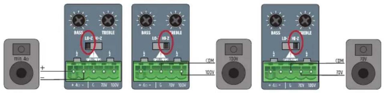
9 SPEAKER OUTPUT
The speaker output with terminal block connection (terminal block included) enables the use of low impedance speakers with an impedance of at least 4 Ohm (LO-Z/HI-Z switch in LO-Z position) or 70/100-V speakers (LO-Z/HI-Z switch in HI-Z position). Please refer to the correct assignment of the terminal block poles (see figure below). The sound of the speaker signal is adjusted using the BASS and TREBLE controls. The total output power of the connected speakers should roughly correspond to the amplifier power.
10 STANDBY ON/OFF
If the standby function is activated (STANDBY in ON position), the speaker is automatically set to standby mode if there is no audio signal for 20 minutes. This reduces power consumption considerably. As soon as there is an audio signal, the amplifier automatically starts from the standby mode and is ready for full use within around 3 seconds (the standby LED flashes white on the front of the device when starting). If the STANDBY LED is white, the device is ready for use. The LED is lit red in standby mode. In addition, the IMA 60 can also be switched to standby mode manually by pressing the standby button on the front. In this case, auto standby mode is deactivated and the device no longer starts automatically. Please note: When the auto standby switch is active, the Bluetooth connection status is also analyzed. When a Bluetooth connection with an auxiliary device (e.g. Smartphone or tablet) is detected and Bluetooth is selected as the signal source, the device is not automatically put in standby mode.

11 CHANNEL 1
Volume control for channel 1 with white SIG (signal) and red CLIP LED. As soon as there is an audio signal on channel 1 and volume control 1 is set to the desired volume, the white signal LED lights up. If the red CLIP LED lights up, the signal may be distorted. In this case, reduce the the channel volume control (control 1) on the amplifier. Should the audio signal be distorted, please check the corresponding input level on the back of the amplifier CLIP LED/GAIN).
12 CHANNEL 2
Volume control for channel 2 with white SIG (signal) and red CLIP LED. As soon as there is an audio signal on channel 2 and volume control 2 is set to the desired volume, the white signal LED lights up. If the red CLIP LED lights up, the signal may be distorted. In this case, reduce the channel volume control (control 2) on the amplifier. Should the audio signal be distorted, please check the corresponding input level on the back of the amplifier (CLIP LED/GAIN).
13
Touch-sensitive button for selecting the audio source of the MUSIC channel (Bluetooth module, input with CD symbol, input with cable symbol). To switch the signal source, press the button for at least half a second. Activation of the individual signal sources takes place clockwise.
14
Touch-sensitive button for activating the Bluetooth connection (pairing). The connection of a Bluetooth auxiliary device (e.g. Smartphone, tablet, etc) to the Bluetooth module of the amplifier is via the selection of the Bluetooth signal source (see element 13). If no auxiliary device is connected to the Bluetooth module, this is indicated by the Bluetooth symbol flashing slowly. In this mode, the IMA60 is not visible to external auxiliary devices. Only previously connected auxiliary devices can be connected directly to the IMA60 without activating pairing mode. In order to prevent an unwanted or unexpected connection, this connection is not created automatically but must be manually created in the Bluetooth menu of the auxiliary device.
To connect to a new auxiliary device, press the Bluetooth pairing button for around 2 seconds until the Bluetooth symbol flashes rapidly. The Bluetooth ID is now visible to other Bluetooth devices. Activate the Bluetooth function on the auxiliary device and search for nearby Bluetooth devices in the Bluetooth menu. When the LD IMA 60 appears under "available devices", you just need to select it and the connection will be made automatically. If this process is successful, the Bluetooth symbol is permanently lit on the front of the amplifier and the Bluetooth ID is no longer visible to other devices. This prevents unauthorized connections to the Bluetooth module. Playback from the auxiliary device can now be started. If you want to disconnect the connection with a Bluetooth device so that the Bluetooth module can be connected to another device, press the Bluetooth button again for around 2 seconds. You can then connect the desired auxiliary device via its setup menu in which you select the LD IMA 60 in the Bluetooth menu (connected devices) of the auxiliary device.
15 MUSIC
Volume control for MUSIC channel with white SIG (signal) and red CLIP LED. As soon as there is an audio signal on the MUSIC channel and the corresponding volume control is set to the desired volume, the white signal LED lights up. If the red CLIP LED lights up, the signal may be distorted. In this case, reduce the output level of the auxiliary device or the channel volume control (MUSIC control) on the amplifier.
16 MASTER VOLUME CONTROL
The main volume control is used to control the sum signal of all channels except the EMERGENCY channel. The EMERGENCY channel bypasses the main volume control, and the signal is sent directly to the power amplifier and the speaker output. The main volume control is equipped with a ring-shaped, three-color LED display. This LED ring remains dark when there is no signal or only a very weak signal at the output, and starts to light up as soon as a sufficient signal level is detected. If the internal limiter is on, the ring lights up yellow. A red light indicates that the protection circuit of the amplifier has been activated due to a technical problem (e.g. short circuit in the speaker cable). In this case, the output is muted. Turn the device off. If the technical problem cannot be solved, please contact an authorised service centre.
17 PRIO
The indicator for activated priority mode of the MIC/LINE channel (priority levels 2, 3 and 4). The priority function of the MIC/LINE channel is activated in the following three situations and the PRIO indicator is lit yellow on the front.
-
The VOX switching circuit is active (input signal level MIC/LINE 1 exceeds the VOX threshold value indicated).
-
The contact between poles C and + of the terminal block connections for MIC/LINE 1 channel is closed using a mute switch/button.
-
The chime tone is played.
Further information on the channel priorities and the EMERG and PRI0 indicators on the front of the amplifier can be found in the PRIORITY LEVELS table in these instructions.
18 EMERG
Indicator for the priority function of the EMERGENCY channel. The EMERG indicator is lit yellow if priority level 1 is activated for VOX emergency circuit or a connected mute switch/button (contact closure). All other input channels are muted during this time. As soon as the contact closure is opened again or the emergency signal level falls below the VOX threshold value, the muting of all channels is cancelled and the EMERG indicator goes out.
19 STANDBY BUTTON
Briefly press the standby button to put the amplifier into standby mode and mute the speaker outputs. If the standby button is briefly pressed again, the amplifier is ready for operation again. If standby mode is activated by pressing the standby button, reactivation of the amplifier via the automatic standby function is not available, even if an audio signal is detected.
20 STANDBY LED
Dual-color LED to indicate the current operating mode. The standby LED is lit white if the amplifier is ready for operation. The LED is lit red in standby mode.
PRIORITY LEVELS
| Priority levels Trigger | signal source Muted signal sources Active signal | sources | Indicator on the front | |
| 1 | Emergency VOX switching circuit and contact closure | MIC/LINE 1 | EMERGENCY SIGNAL EMERG MIC/LINE 2 | |
| MUSIC | ||||
| 2 MIC/LINE 1 | VOX | MIC/LINE 2 EMERGENCY SIGNAL | PRIO | |
| MUSIC MIC/LINE 1 | ||||
| 3 | MIC/LINE 1, contact closure during chime tone output | MIC/LINE 1 | EMERGENCY SIGNAL PRIO MIC/LINE 2 | |
| MUSIC | ||||
| 4 | MIC/LINE 1, contact closure after chime tone output | MUSIC | EMERGENCY SIGNAL | PRIO MIC/LINE 1 |
| MIC/LINE 2 | ||||
| 5-- | EMERGENCY SIGNAL | - | ||
| MIC/LINE 1 | ||||
| MIC/LINE 2 | ||||
| MUSIC | ||||
CONNECTION EXAMPLES

flowchart
graph TD
    A["Active Subwoofer"] --> B["AUX OUT"]
    B --> C["ML 8C"]
    C --> D["MIC/LINE 2"]
    D --> E["MIC/LINE 1"]
    E --> F["EMERGENCY"]
    F --> G["Call Station"]
    B --> H["STANDBY"]
    H --> I["100 V"]
    I --> J["100 V"]
    J --> K["100 V"]
    K --> L["100 V"]
    style A fill:#f9f,stroke:#333
    style B fill:#ccf,stroke:#333
    style C fill:#cfc,stroke:#333
    style D fill:#fcc,stroke:#333
    style E fill:#cff,stroke:#333
    style F fill:#ffc,stroke:#333
    style G fill:#cfc,stroke:#333
    style H fill:#cfc,stroke:#333
    style I fill:#cfc,stroke:#333
    style J fill:#cfc,stroke:#333
    style K fill:#cfc,stroke:#333
    style L fill:#cfc,stroke:#333
The connection for a mute switch/button in MIC/LINE channel 1 can be used for two devices at the same time (muting of a music signal or activation of the gong/signal tone). In this case, the mute contacts of both devices must be connected to poles C and + of the terminal strip connections for MIC/LINE 1.
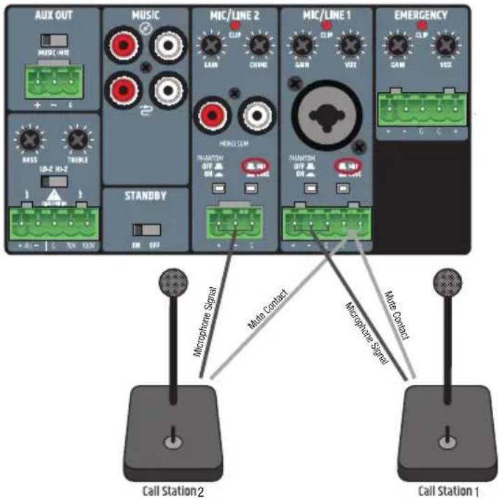
When wiring terminal blocks, please ensure that the poles/terminals are correctly assigned (see figure under the connection examples for terminal blocks). The manufacturer takes no responsibility for damage caused by faulty wiring! Further information on the correct wiring of terminal block connections ("terminal blocks") can be found in the section TERMINAL BLOCK CONNECTIONS in these instructions.
TERMINAL BLOCK CONNECTIONS
AUX OUT OUTPUT LINE
balanced wiring unbalanced wiring


SPEAKER CONNECTIONS (LOW IMPEDANCE, 100 V AND 70 V SPEAKER)
CHANNEL 1 AND 2 INPUTS
balanced wiring balanced wiring unbalanced wiring

EMERGENCY CHANNEL INPUTS
balanced wiring

In the factory settings, the EMERGENCY signal is routed via an internal jumper to the AUX OUT line output. If this setting needs to be changed, the device must be opened and the corresponding jumper removed.

Caution:
Warning! Danger of electric shock! Dangerous voltages inside the device!
Opening the device and changing the configuration using a jumper requires specialist technical knowledge and may only be carried out by a specially trained person! If you are not qualified to do this, never carry out such interventions yourself, but instead contact a trained service technician.
Be careful when opening the amplifier and changing the configuration. This will avoid damage to property and persons. Follow the individual steps in these instructions. The manufacturer takes no responsibility for damage to property and persons due to improper use.
- Disconnect the amplifier from the mains (pull out the mains plug)!
- Disconnect all cables from the amplifier.
- Wait for at least one minute before opening the housing to make sure there is no longer any voltage inside!
- Loosen and remove the two screws on each side of the amplifier A, the four marked screws on the back B and a screw on the top of the amplifier C with a suitable tool (9 screws in total). Note the positions of the three different types of screws.
- Pull the housing cover off the housing from behind.
- Remove the jumper ☐ (marked in figure 2) from the contacts (inside back of the device).
- Slide the housing cover onto the housing from the rear and fasten it using the previously removed screws.
Now the emergency signal of the EMERGENCY channel is no longer routed to the AUX OUT output.


natural_image
Red electronic circuit board with components and a magnified inset showing a close-up of a device (no visible text or symbols)RACK INSTALLATION (LDIMARK rack installation kit provided as an option)
The optionally available LDIMARK rank installation kit contains housing adapters and connecting pieces for the permanent installation of IMA 30 or IMA 60 mixing amplifiers (single or two side by side) in a 19" rack.
The installation kit includes the following components:
2 rack adapters with short sides A, 1 rack adapter with long sides B, 2 small plates for the back C, 2 rectangular plates for the bottom D, 4 M4 pan-head screws for the rack brackets, 8 M3 sunkenhead screws for plates D.

natural_image
Technical diagram of a rectangular electronic component with labeled sections A, B, and C/D (no text or symbols beyond labels)The installation of a single amplifier requires one short-sided rack adapter A and the long-sided rack adapter B. Screw the adapter with the short side to either the left or right side of the amplifier and the adapter with the long sides to the opposite side. Use the M4 pan head screws for this.

natural_image
Technical line drawing of a device housing with labeled components A and B, showing internal components and mounting points (no text or symbols beyond labels)If you want to install two amplifiers side by side in a 19" rack, you will need the two small plates to connect the amplifiers together at the back C, the two rectangular plates for interconnection at the bottom D and the two rack adapters with short sides A. Loosen the corresponding screws on the back and screw the plates down with these screws C. Screw the connecting pieces D in with the enclosed M3 countersunk head screws to the intended positions on the amplifiers, as shown below. Screw the two rack adapters with the short sides A to the sides of the device using the M4 pan-head screws.

natural_image
Front view of a rack-mounted electronic device with multiple ports and connectors (no visible text or labels)
natural_image
Technical line drawing of a mechanical or electronic assembly with no visible text, numbers, or symbols.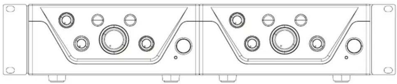
natural_image
Technical line drawing of a mechanical housing or enclosure with circular components and mounting holes (no text or symbols)UNDER-TABLE INSTALLATION (rack adapter optional with LDIMARK rack installation kit).
Two M4 threaded holes are provided at the top of the corners of the amplifier housing for under-table installation. Screw the two rack adapters with the short sides to the two sides of the housing using the M4 pan-head screws provided (see figure). The amplifier can now be installed in the desired position under a table.

natural_image
Technical line drawing of a computer chassis with labeled ports (no text or symbols beyond labels A and B)TECHNICAL DATA
| Item description LDIMA60 | |
| Product type Installation mixing amplifier | |
| Emergency signal input 1 balanced line input | |
| Mic/line inputs 2 | |
| Music sources 2 unbalanced stereo line inputs + 1 Bluetooth interface Version 4.0 | |
| Line outputs 1 | |
| Speaker outputs 1 with Low-Z/High-Z mode selector | |
| Cooling Convection cooling | |
| Priority levels 4 | |
| Emergency input (emergency signal) | |
| Nominal input sensitivity -15 dBu (Sine wave, 1 kHz, max. gain) | |
| Nominal input clipping 20 dBu (Sine wave, 1 kHz) | |
| Harmonic distortion (THD+N) | <0.05% (SPK OUT, -6 dBu, 20 Hz - 20 kHz, max. gain, 20 kHz bandwidth)<0.01% (AUX OUT, -6 dBu, 20 Hz - 20 kHz, max. gain, 20 kHz bandwidth) |
| Frequency response 10 Hz - 20 kHz (Low-Z SPK OUT, -3 dB)10 Hz - 20 kHz (AUX OUT, -3 dB) | |
| Input impedance 10 kohm (balanced) | |
| Signal-to-noise ratio | >88 dB (SPK OUT, -6 dBu, CH max. gain (0 dB), master gain min. (-inf), 20 kHz bandwidth, A-weighted)>87 dB (AUX OUT, -6 dBu, CH max. gain (0 dB), 20 kHz bandwidth, A-weighted) |
| Signal-to-noise ratio (Best conditions) | >92 dB (SPK OUT, +18 dBu, max. gain (0 dB), master gain max. (0 dB), 22 kHz bandwidth, A-weighted)>110 dB (AUX OUT, +18 dBu, max. gain (0 dB), 22 kHz bandwidth, A-weighted) |
| Common mode rejection (CMRR) >48 dB (SPK OUT, AUX OUT, -6 dBu, 1 kHz) | |
| Gain | -15 dB to 42 dB |
| VOX threshold value | 0%: Off, 25%: -6 dBu, 50%: -27 dBu, 100%: -35 dBu |
| Priority contact closure | +5 V DC, Normally open for potential-free contact |
| Connector | 1 x 5-pole terminal block (pitch 5.08 mm) |
| Standby wake up threshold | -40 dBu |
| Mic/line inputs 1-2 | |
| Nominal input sensitivity | Mic: -40 dBu (sine wave, 1 kHz, max. gain)Line: -20 dBu (sine wave, 1 kHz, max. gain) |
| Nominal input clipping Mic: -5 dBu (sine wave, 1 kHz)Line:+19 dBu (sine wave, 1 kHz) | |
| Harmonic distortion (THD+N) | Mic: <0.2% (SPK OUT, -42 dBu, 20 Hz - 20 kHz, max. gain, 20 kHz bandwidth)<0.02% (AUX OUT, -38 dBu, 20 Hz - 20 kHz, max. gain, 20 kHz bandwidth)Line: <0.1% (SPK OUT, +4 dBu, 20 Hz - 20 kHz, CH max. gain, master max. gain (0 dB), 20 kHz bandwidth)<0.02% (AUX OUT, +4 dBu, 20 Hz - 20 kHz, CH max. gain, 20 kHz bandwidth) |
| Frequency response | Mic: 170 Hz - 20 kHz (SPK OUT, -3 dB)150 Hz - 20 kHz (AUX OUT, -3 dB)Line: 19 Hz - 20 kHz (SPK OUT, -3 dB)20 Hz - 20 kHz (AUX OUT, -3 dB) |
| Input impedance Mic: 1.2 kohm (balanced)Line: 10 kohm (balanced) | |
| Signal-to-noise ratio | Mic: >80 dB (SPK OUT, -38 dBu, max. gain (0 dB), master gain max. (0 dB), 22 kHz bandwidth, A-weighted)>80 dB (AUX OUT, -38 dBu, max. gain (0 dB), 22 kHz bandwidth, A-weighted)Line: >90 dB (SPK OUT, +4 dBu, CH max. gain (0 dB), master gain max. (0 dB), 20 kHz bandwidth, A-weighted)>89 dB (AUX OUT, +4 dBu, CH- max. gain (0 dB), 20 kHz bandwidth, A-weighted) |
| Signal-to-noise ratio (Best conditions) | Mic: >90 dB (SPK OUT, -5 dBu, CH max. gain (0 dB), master gain (-20 dB), 20 kHz bandwidth, A-weighted)>102 dB (AUX OUT, -18 dBu, max. gain (0 dB), 20 kHz bandwidth, A-weighted)Line: >90 dB (SPK OUT, +18 dBu, CH max. gain (0 dB), master gain (-14 dB), 20 kHz bandwidth, A-weighted)>103 dB (AUX OUT, +18 dBu, max. gain (0 dB), 20 kHz bandwidth, A-weighted) |
| Common mode rejection (CMRR) Mic: >40 dB (SPK OUT, AUX OUT, 1 kHz)Line: >45 dB (SPK OUT, AUX OUT, 1 kHz) | |
Item description LDIMA60
Mic/line inputs 1-2
| Gain Mic: 12 dB ... 66 dB (SPIK) / 42 dB (AUX OUT)Line: -37 ... 44 dB (SPIK) / 18 dB (AUX OUT) |
| Phantom power +24 V, 10 mA, switchable |
| VOX threshold value Mic: 0%: Off, 25%: -40 dBu, 50%: -52 dBu, 100%: -66 dBuLine: 0%: Off, 25%: -6 dBu, 50%: -27 dBu, 100%: -35 dBu |
| Priority contact closure +5 V DC, Normally open for potential-free contact |
| Connections Mic/Line 1: 5-pole terminal blocks, pitch 5.08 mm + 1 XLR/6.3 mm jack (combo socket)Mic/Line 2: 3-pole terminal block, pitch 5.08 mm + 1 dual RCA (summed to mono) |
| Standby wake up threshold Mic: -70 dBuLine: -35 dBu (Line), -40 dBu (mono sum) |
Chime tone
| Playback time 2 s | |
| Resolution 12 Bit | |
| Music inputs - CD/Aux | |
| Nominal input sensitivity -6.2 dBV (sine wave, 1 kHz, max. gain) | |
| Nominal input clipping 8 dBV (sine wave, 1 kHz) | |
| Connectors 2 Dual RCA summed to mono | |
| Harmonic distortion (THD+N) | <0.05% (SPK OUT, -6 dBu, 20 Hz - 20 kHz, CH max. gain, master max. gain (0 dB), 20 kHz bandwidth)<0.01% (AUX OUT, -6 dBu, 20 Hz - 20 kHz, CH max. gain, 20 kHz bandwidth) |
| Frequency response 20 Hz - 20 kHz (SPK OUT, -3 dB)20 Hz - 20 kHz (AUX OUT, -3 dB) | |
| Input impedance 20 kOhm (unbalanced) | |
| Signal-to-noise ratio | >86 dB (SPK OUT, -4 dBu, CH-Gain Max. (0 dB), master gain max. (0 dB), 20 kHz bandwidth, A-weighted)>90 dB (AUX OUT, -6 dBu, CH max. gain (0 dB), 20 kHz bandwidth, A-weighted) |
| Signal-to-noise ratio(best conditions) | >90 dB (SPK OUT, +10 dBu, CH max. gain (0 dB), master gain (-16 dB), 20 kHz bandwidth, A-weighted)>104 dB (AUX OUT, +10 dBu, max. gain (0 dB), 20 kHz bandwidth, A-weighted) |
| Gain -Inf ... 5 dB (SPK) / 30 dB (AUX OUT) | |
| Standby wake up threshold -45 dBu | |
Music inputs - BT
| Harmonic distortion (THD+N) | <0.2% (SPK OUT, -10 dBFs, 20 Hz - 20 kHz, max. gain, 20 kHz bandwidth)<0.2% (AUX OUT, -10 dBFs, 20 Hz - 20 kHz, max. gain, 20 kHz bandwidth) |
| Frequency response 25 Hz - 20 kHz (SPK OUT, -3 dB) | |
| 25 Hz - 20 kHz (AUX OUT, -3 dB) | |
| Signal-to-noise ratio | >80 dB (SPK OUT, -10 dBFs), max. gain (0 dB), 20 kHz bandwidth, A-weighted)>80 dB (AUX OUT, -10 dBFs, max. gain (0 dB), 20 kHz bandwidth, A-weighted) |
| Signal-to-noise ratio(best conditions) | >86 dB (SPK OUT, 0 dBFs, CH max. gain (0 dB), master gain (-10 dB), 20 kHz bandwidth, A-weighted)>93 dB (AUX OUT, 0 dBFs, max. gain (0 dB), 20 kHz bandwidth, A-weighted) |
Amplifier outputs
| Device type | Class D |
| Power amplifier outputs | Low-Z: min. 4 Ohm load, High-Z: 70 V or 100 V outputs |
| Connector | 5-pole terminal block (pitch 5.08 mm) |
| Output power (RMS) | 65 W (continuous sine wave, 1 kHz, 4 Ohm load) |
| Output power (peak) 70 W (100 ms sine burst, 1 kHz, 4 Ohm load) | |
| Frequency response 20 Hz - 20 kHz (Low-Z, -3 dB) | |
| 60 Hz - 20 kHz (High-Z, -3 dB) | |
| Tone control | BASS: +/-10 dB (100 Hz), TREBLE: +/-10 dB (10 kHz) |
| Protection circuits: | Audio limiter (control range 10 dB), over/undervoltage, overheating, short circuit, direct current offset |
AUX output
| Connector | 3-pole terminal block (pitch 5.08 mm) |
| Frequency response 20 Hz – 20 kHz (-3 dB) | |
| Max. Output level 22 dBu | |
Item description LDIMA60
Power supply
Type Switch mode power supply
Operating voltage 100 V AC - 240 V AC (+/-10%), 50 - 60 Hz
Mains fuse T2.5A 250V
Connector IEC power supply socket
Safety class Class 1
Max. Power consumption 95 W (sine burst, 1 kHz, 4 Ohm load)
Power consumption, idle mode 7.5 W (no input signal)
Power consumption, standby mode <1 W
Ambient temperature (in operation) 0^ C ... 40^ C; <85% humidity, non-condensing
General data
Time to standby 20 min.
Material Steel housing, plastic front panel
Measurements (W x H x D) 210 x 95 x 266.76 mm (height with rubber feet)
Weight 2.51 kg
Optional accessory Rack hardware
MANUFACTURER'S DECLARATIONS
MANUFACTURER'S WARRANTY & LIMITATIONS OF LIABILITY
You can find our current warranty conditions and limitations of liability at: https://cdn-shop.adamhall.com/media/pdf/MANUFACTURERS-DECLARATIONS_LD_SYSTEMS.pdf To request warranty service for a product, please contact Adam Hall GmbH, Adam-Hall-Str. 1, 61267 Neu Anspach / Email: Info@adamhall.com / +49 (0)6081 / 9419-0.

CORRECT DISPOSAL OF THIS PRODUCT
(valid in the European Union and other European countries with a differentiated waste collection system)
This symbol on the product, or on its documents indicates that the device may not be treated as household waste. This is to avoid environmental damage or personal injury due to uncontrolled waste disposal. Please dispose of this product separately from other waste and have it recycled to promote sustainable economic activity. Household users should contact either the retailer where they purchased this product, or their local government office, for details on where and how they can recycle this item in an environmentally friendly manner. Business users should contact their supplier and check the terms and conditions of the purchase contract. This product should not be mixed with other commercial waste for disposal.
FCC STATEMENT
This device complies with Part 15 of the FCC Rules. Operation is subject to the following two conditions:
(1) This device may not cause harmful interference, and
(2) This device must accept any interference received, including interference that may cause undesired operation
CE COMPLIANCE
Adam Hall GmbH states that this product meets the following guidelines (where applicable):
R&TTE (1999/5/EC) or RED (2014/53/EU) from June 2017
Low voltage directive (2014/35/EU)
EMV directive (2014/30/EU)
RoHS (2011/65/EU)
The complete declaration of conformity can be found at www.adamhall.com.
Furthermore, you may also direct your enquiry to info@adamhall.com.
EU DECLARATION OF CONFORMITY
Hereby, Adam Hall GmbH declares that this radio equipment type is in compliance with Directive 2014/53/EU.
The full text of the EU declaration of conformity is available at the following
internet address: www.adamhall.com/compliance/
DEUTSCH
natural_image
Interior view of an electronic circuit board with visible components and wiring (no readable text or symbols)natural_image
Technical line drawing of a rectangular electronic component with mounting holes and labeled parts (A, B, C, D), no readable text or symbols beyond labels.natural_image
Technical line drawing of a mechanical component with labeled sections A and B, showing internal components and mounting holes (no text or symbols beyond labels)natural_image
Front view of a rack-mounted electronic device with multiple ports and connectors (no visible text or labels)
natural_image
Technical line drawing of a mechanical or electrical enclosure with multiple circular components and mounting brackets (no text or symbols)
natural_image
Technical line drawing of a mechanical housing or enclosure with multiple circular components and mounting flanges (no text or symbols)natural_image
Technical line drawing of a computer chassis with labeled ports (no text or symbols beyond labels A)TECHNISCHE DATEN
3 ON/OFF (MARCHE/ARRÊT)
CAVALIER POUR LE SIGNAL D'URGENCE SUR AUX OUT
natural_image
Red electronic circuit board with various components and wiring, no visible text or symbolsMONTAGE EN RACK (kit de montage en rack LDIMARK fourni en option)
natural_image
Technical diagram of a rectangular electronic component with labeled sections A, B, and C, showing mounting holes and housing (no text or symbols beyond labels)natural_image
Technical line drawing of a mechanical component with labeled sections A and B, showing internal components and mounting holes (no text or symbols beyond labels)natural_image
Front view of a computer rack with multiple ports and connectors (no visible text or labels)
natural_image
Technical line drawing of a mechanical or electrical enclosure with mounting holes and control panel (no text or symbols)
natural_image
Technical line drawing of a mechanical housing with multiple circular components and mounting holes (no text or symbols)natural_image
Technical line drawing of a computer chassis with labeled ports (no text or symbols beyond labels A)CARACTÉRISTIQUES TECHNIQUES
(Valid in the European Union and other European countries with waste separation)
DÉCLARATION DE CONFORMITÉ CE
natural_image
Red electronic circuit board with components and wiring, no visible text or symbolsnatural_image
Technical line drawing of a rectangular electronic component with mounting holes and labeled parts A, B, C, D (no text or symbols beyond labels)natural_image
Technical line drawing of a mechanical housing component with mounting flanges and circular features (no text or symbols)natural_image
Front view of a rack-mounted electronic device with multiple ports and connectors (no visible text or labels)
natural_image
Technical line drawing of a mechanical or electrical enclosure with mounting brackets and control panel (no text or symbols)
natural_image
Technical line drawing of a mechanical housing or enclosure with multiple circular components and mounting holes (no text or symbols)natural_image
Technical line drawing of a computer chassis with labeled ports (A), showing internal components and mounting brackets (no text or symbols beyond labels)DATOS TÉCNICOS
ZWORKA AWARYJNEGO SYGNAŁU DLA WYJŚCIA AUX OUT
natural_image
Red electronic circuit board with various components and wiring, no visible text or symbolsnatural_image
Technical line drawing of a rectangular electronic component with mounting holes and labeled parts A, B, C, D (no text or symbols beyond labels)natural_image
Technical line drawing of a mechanical component with labeled sections A and B, showing internal circular features and mounting holes (no text or symbols beyond labels)natural_image
Front view of a rack-mounted electronic device with multiple ports and connectors (no visible text or labels)
natural_image
Technical line drawing of a mechanical or electrical enclosure with mounting holes and control panel (no text or symbols)
natural_image
Technical line drawing of a mechanical housing with circular components and mounting holes (no text or symbols)natural_image
Technical line drawing of a computer chassis with labeled ports (no text or symbols beyond labels A and C)DANE TECHNICZNE
DEKLARACJA ZGODNOŚCI WE
9 USCITA DIFFUSORE SONORO
LINEA USCITA AUX OUT
PONTE PER SEGNALE DI EMERGENZA SU AUX OUT
natural_image
Interior view of an electronic circuit board with components and wiring (no visible text or symbols)natural_image
Technical line drawing of a rectangular electronic component with mounting holes and labeled parts (A, B, C, D), no readable text or symbols beyond labels.natural_image
Technical line drawing of a mechanical component with labeled sections A and B, showing internal circular features and mounting holes (no text or symbols beyond labels)natural_image
Front view of a rack-mounted electronic device with multiple ports and connectors (no visible text or labels)
natural_image
Technical line drawing of a mechanical or electrical enclosure with mounting brackets and control panel (no text or symbols)
natural_image
Technical line drawing of a mechanical housing with circular components and mounting holes (no text or symbols)natural_image
Technical line drawing of a computer chassis with labeled ports (no text or symbols beyond labels A and C)DATI TECNICI
natural_image
Red electronic circuit board with various components and wiring, no visible text or symbolsnatural_image
Technical line drawing of a rectangular electronic component with mounting holes and labeled parts (A, B, C, D), no readable text or symbols beyond labels.natural_image
Technical line drawing of a device housing with labeled components A and B, showing internal components and mounting points (no text or symbols beyond labels)natural_image
Front view of a dual-chamber electronic device chassis with labeled ports (A and C), no readable text or symbols beyond labels
natural_image
Technical line drawing of a mechanical or electronic assembly with no visible text, numbers, or symbols.
natural_image
Technical line drawing of a mechanical housing with circular components and mounting holes (no text or symbols)natural_image
Technical line drawing of a computer chassis with labeled ports (no text or symbols beyond labels A)


- IMA 60
- CONTENTS / INHALTSVERZEICHNIS / CONTENU / CONTENIDO / TREŚĆ / CONTENUTO / ОГЛАВЛЕНИЕ
- ENGLISH
- DEUTSCH
- SAFETY INFORMATION
- FOR DEVICES WITH GRID CONNECTION
- WARNING
- CAUTION! HIGH VOLUMES IN AUDIO PRODUCTS!
- INTRODUCTION
- FEATURES
- CONNECTIONS, CONTROLS AND DISPLAY ELEMENTS
- POWER CONNECTOR
- FUSE
- ON/OFF
- EMERGENCY
- MIC/LINE 1
- MIC/LINE 2
- MUSIC
- AUX OUT
- SPEAKER OUTPUT
- STANDBY ON/OFF
- CHANNEL 1
- CHANNEL 2
- 13
- 14
- MUSIC
- MASTER VOLUME CONTROL
- PRIO
- EMERG
- STANDBY BUTTON
- STANDBY LED
- TERMINAL BLOCK CONNECTIONS
- AUX OUT OUTPUT LINE
- Caution:
- Warning! Danger of electric shock! Dangerous voltages inside the device!
- RACK INSTALLATION (LDIMARK rack installation kit provided as an option)
- UNDER-TABLE INSTALLATION (rack adapter optional with LDIMARK rack installation kit).
- Item description LDIMA60
- Power supply
- General data
- MANUFACTURER'S DECLARATIONS
- MANUFACTURER'S WARRANTY & LIMITATIONS OF LIABILITY
- CORRECT DISPOSAL OF THIS PRODUCT
- FCC STATEMENT
- CE COMPLIANCE
- EU DECLARATION OF CONFORMITY
- ON/OFF (MARCHE/ARRÊT)
- CAVALIER POUR LE SIGNAL D'URGENCE SUR AUX OUT
- MONTAGE EN RACK (kit de montage en rack LDIMARK fourni en option)
- DÉCLARATION DE CONFORMITÉ CE
- ZWORKA AWARYJNEGO SYGNAŁU DLA WYJŚCIA AUX OUT
- DEKLARACJA ZGODNOŚCI WE
- USCITA DIFFUSORE SONORO
- LINEA USCITA AUX OUT
- PONTE PER SEGNALE DI EMERGENZA SU AUX OUT
Brand : LD Systems
Model : IMA 60
Category : Receiver