Elite - DJ Equipment Reloop - Free user manual and instructions
Find the device manual for free Elite Reloop in PDF.
| Product type | Professional DJ mixer console |
| Brand | Reloop |
| Model | Elite |
| Manufacturer | Global Distribution GmbH & Co. KG, Münster, Germany |
| Dimensions (W x D x H) | 290 x 426 x 105 mm (knobs: 18.5 mm) |
| Weight | 6.3 kg |
| Power supply | AC 100-240 V, 50/60 Hz |
| Frequency response | 20 Hz - 20 kHz |
| Audio inputs | 2x Phono RCA, 2x Line RCA, AUX RCA, Mic/Line 6.3 mm jack |
| Audio outputs | Master XLR (balanced), Master RCA, Booth 6.3 mm jack, Record RCA, Headphone 6.3/3.5 mm |
| Channel EQ | 3-band (Low 70 Hz, Mid 1 kHz, High 13 kHz), total cut -45 dB, boost +12 dB |
| Mic EQ | 2-band (100 Hz, 10 kHz), -26 dB / +12 dB |
| Built-in effects | Filter, BitCrush, Whitenoise, Flanger (TweakFX) |
| Crossfader | Adjustable curve and reverse |
| Line fader | Adjustable curve and reverse |
| DVS control | Compatible with Serato DJ Pro (license included) |
| Performance pads | 8 velocity-sensitive pads, 12 modes |
| USB connectivity | Dual USB 2.0 ports |
| Microphone | DJ Mic input with volume, EQ and Talkover (Active Ducking Technology) |
| Included accessories | USB cable, power cable, 2 Serato Control vinyls, BPM Supreme 90-day subscription, Serato DJ Pro license |
| Maintenance | Clean with a damp cloth, avoid solvents; regularly check wear of knobs and sliders |
| Safety | Do not open the housing, avoid humidity, use same type fuses, unplug before cleaning |
| Firmware update | Via USB, .bin file, downloadable at www.reloop.com |
Frequently Asked Questions - Elite Reloop
User questions about Elite Reloop
0 question about this device. Answer the ones you know or ask your own.
Ask a new question about this device
Download the instructions for your DJ Equipment in PDF format for free! Find your manual Elite - Reloop and take your electronic device back in hand. On this page are published all the documents necessary for the use of your device. Elite by Reloop.
USER MANUAL Elite Reloop
Deutsch 02-11
English 12-21
Francais 22-31
Espanol 32-41

HIGH PERFORMANCE DVS MIXER FOR SERATO

Bedienungsanleitung
ACHTUNG!
For your own safety, please read this operation manual carefully before initial operation! All persons involved in the installation, setting-up, operation, maintenance and service of this device must be appropriately qualified and observe this operation manual in detail. This product complies with the requirements of the applicable European and national regulations. Conformity has been proven. The respective statements and documents are deposited at the manufacturer.
Mode d'emploi
ATTENTION!
To prevent fire or avoid an electric shock do not expose the device to water or fluids!
Never open the housing!
ATTENTION!
Keep information for further reference!
MIC BTH (Mic Booth) 8
MIC LOW CUT 8
AUX GAIN COMPENSATION 8
MIDI 8
LED CHECK. 8
FACT RST (Factory Reset) 9
FW UPDT (Firmware Update) 9
ABOUT 9
EXIT 9
4.SeratoDJ DVS. 9
C21....LoopEncoder
C22....Loop Length Bar
C23. .Manueller Loop-Tast
| USB Sub Value Type Channel Control Value MIDI Out Request | ||||||||
| OUT 1+2 | PHONO Control Tone | SW | CC | N | 32 | 0 | X | X |
| CD Control Tone | SW | CC | N | 32 | 1 | X | X | |
| CF A | SW | CC | N | 32 | 2 | X | X | |
| CF B | SW | CC | N | 32 | 3 | X | X | |
| MIC | SW | CC | N | 32 | 4 | X | X | |
| Aux | SW | CC | N | 32 | 5 | X | X | |
| Post Fader Deck 1 | SW | CC | N | 32 | 6 | X | X | |
| None | SW | CC | N | 32 | 7 | X | X | |
| OUT 3+4 | PHONO Control Tone | SW | CC | N | 32 | 0 | X | X |
| CD Control Tone | SW | CC | N | 32 | 1 | X | X | |
| CF A | SW | CC | N | 32 | 2 | X | X | |
| CF B | SW | CC | N | 32 | 3 | X | X | |
| MIC | SW | CC | N | 32 | 1 | X | X | |
| Aux | SW | CC | N | 32 | 5 | X | X | |
| Post Fader Deck 2 | SW | CC | N | 32 | 6 | X | X | |
| None | SW | CC | N | 32 | 7 | X | X | |
| OUT 5+6 | REC OUT | SW | CC | R | 7F | 0 | X | X |
| CF A | SW | CC | R | 7F | 1 | X | X | |
| CF B | SW | CC | R | 7F | 2 | X | X | |
| MIC | SW | CC | R | 7F | 3 | X | X | |
| Aux | SW | CC | R | 7F | 4 | X | X | |
| Post Fader Deck 1 | SW | CC | R | 7F | 5 | X | X | |
| Post Fader Deck 2 | SW | CC | R | 7F | 6 | X | X | |
| None | SW | CC | R | 7F | 7 | X | X | |
Filter Resonanz
FW UPDT (Firmware Update)
Safety instructions 13
Application in accordance with regulations 13
Maintenance 13
- Overview 14
1.1 Graphics 14
User Interface 14
Front-Side. 15
Backside 15
1.2 Designations 15
A Serato DJ Pro Effect Section 15
B Mixer Section. 15
C Loop Section 15
D Performance Mode Section 15
E Navigation Section 15
F Front Controls. 15
G Connections 15
1.3 Connecting the ELITE 16
Line Signals 16
Phono Signals. 16
Microphone 16
Headphones 16
Master Output 16
Monitor Output 16
Rec Output. 16
Aux Input. 16
Power Supply. 16
USB Connection. 16
RP-8000/Controller USB connection 16
- Operation 17
Power On. 17
Signal Input Select 17
Gain 17
Equalizer 17
TweakFX 17
Linefader 17
Crossfader 17
DJ Mic 17
Monitoring 17
Master Section 17
- Setup-Utility 18
3.1 Menu Structure 18
3.2 Menu Items 18
MASTER OUTPUT 18
MASTERLIMITER 18
FADER SETTINGS 18
FX FADER CONTROL 18
USB OUT SETTINGS 18
FILTER RESO 18
TLKOVRL (Talkover Level) 18
ISO XOVR (Isolator Crossover) 18
SHIFT LOCK 18
VELOCITY SENS 18
PAD SENS (Pad sensitivity) 18
MIC BTH (Mic Booth) 18
MIC LOW CUT 18
AUX GAIN COMPENSATION 18
LED CHECK. 18
FACTORY RESET 18
FIRMWARE UPDATE. 19
ABOUT 19
EXIT 19
- Serato DJ Pro DVS Control 19
4.1 Functionality 19
Navigation Section. 19
Loop Section 19
Performance Mode Section 19
Hot Cue Mode 19
Loop Roll Mode 19
Slicer Mode 19
Sampler Mode 19
Pitch Play Mode 19
Saved Loop Mode 19
Slicer Loop Mode 19
Saved Flips Mode 19
Effect Section 20
4.2 Driver Installation 20
4.3 Connections 20
- Technical Specifications 20
CAUTION!
For your own safety, please read this operation manual carefully before initial operation! All persons involved in the Installation, setting-up, operation, maintenance and service of this device must be appropriately qualified and observe this operation manual in detail. This product complies with the requirements of the applicable European and national regulations. Conformity has been proven. The respective statements and documents are deposited at the manufacturer.
Please remove the Reloop ELITE from its packaging. Check before initial operation to make sure that the device has not been visibly damaged during transport. If you detect any damage to the power cable or the casing, do not operate the device. Contact your specialised dealer.
SAFETY INSTRUCTIONS
CAUTION!
Please exercise particular caution when handling power voltage. This voltage rating may lead to a critical electrical shock! Any damage caused by non-observation of this operation manual excludes any warranty claims. The manufacturer is not liable for any damage to property or for personal injury caused by improper handling or non-observation of the safety instructions.
This device left the factory in perfect condition. To maintain this condition and to ensure a risk-free operation, the user must observe the safety instructions and warnings contained in this operation manual.
- For reasons of safety and certification (CE) the unauthorised conversion and/or modification of the device is prohibited. Please note, that in the event of damage caused by the manual modification to this device, any warranty claims are excluded.
- The inside of the device does not contain any parts which require maintenance, with the exception of wear parts that can be exchanged from the outside. Qualified staff must carry out maintenance, otherwise the warranty does not apply!
The fuse must exclusively be exchanged against fuses of the same class, with the same trigger features and nominal current rating.
- Ensure that the power will only be supplied after the device has been fully set up. Always plug in the mains plug last. Ensure that the mains switch is in the "OFF" position when connecting the device to power.
- Only use cables that comply with regulations. Observe that all jacks and bushes are tightened and hooked up correctly. Refer to your dealer, if you have any questions.
- When setting up the product, ensure that the mains cable is not squashed or damaged by sharp edges.
- Prevent the mains cable from coming into contact with other cables! Exercise great care when handling mains cables and connections. Never touch these parts with wet hands!
- Connect the power cable exclusively to appropriate shock-proof outlets. The only supply point to be used is a supply outlet in accordance with specifications of the public supply network.
- Disconnect the device from the supply outlet when not in use and before cleaning! Be sure to hold the mains plug by the body. Never pull the mains cord!
- Position the device on a horizontal and stable low-flame base.
- Avoid any concussions or violent impact when installing or operating the device.
- When selecting the location of installation, make sure that the device is not exposed to excessive heat, humidity or dust. Be sure that no cables lie around openly. You will endanger your own safety and that of others!
Do not rest any containers filled with liquid that could easily spill onto the device or in its immediate vicinity. If, however, fluids should access the inside of the device, immediately disconnect the mains plug. Have the device checked by a qualified service technician before re-use. Damage caused by fluids inside the device is excluded from warranty.
- Do not operate the device under extremely hot (in excess of 35^ C) or extremely cold (below 5^ C) conditions. Keep the device away from direct exposure to the sun and heat sources, such as radiators, ovens, etc. (even during transport in a closed vehicle). Always ensure sufficient ventilation.
- The device must not be operated after being taken from a cold environment into a warm environment. The condensation caused hereby may destroy your device. Do not switch on or operate the device until it has reached ambient temperature!
- Controls and switches should never be treated with spray-on cleaning agents and lubricants. This device should only be cleaned with a damp cloth. Never use solvents or cleaning fluids with a petroleum base for cleaning.
- When relocating, the device should be transported in its original packaging.
- When starting operation, the crossfaders and volume controls of your amplifier must be set to minimum level. Bring the loudspeaker switches into the "OFF" position. Wait between 8 to 10 seconds before increasing the volume to avoid damage to loudspeakers and diplexer.
Devices supplied by voltage should not be left in the hands of children. Please exercise particular care when in the presence of children.
- At commercial facilities, the regulations for the prevention of accidents as stipulated by the organization of professional associations must be observed.
- At schools, training facilities, hobby and self-help workshops, the operation of the device must be monitored with responsibility by trained staff.
- Keep this operation manual in a safe place for later reference, in the event of questions or problems.
APPLICATION IN ACCORDANCE WITH REGULATIONS
This device is a professional mixing console which can regulate and mix low level audio signals. The device is thereby connected between a signal source and an audio amplifier or active speakers, respectively.
- This product is authorised for connection to AC 100-240 V, 50/60 Hz and is designed exclusively for indoor application.
If the device is used for any other purposes than those described in the operation manual, damage can be caused to the product, leading to the exclusion of warranty rights. Moreover, any other application that does not comply with the specified purpose harbours risks such as short circuit, fire, electric shock, etc.
The serial number determined by the manufacturer must never be removed to uphold the warranty rights.
MAINTENANCE
- Check the technical safety of the device regularly for damage to the mains line or the casing, as well as for wear of wear parts, such as rotary and sliding switches.
- If it is to be assumed that the safe operation is no longer feasible, then the device must be disconnected and secured against accidental use. Always disconnect the mains plug from the outlet!
- It must be assumed that a safe operation is no longer feasible, if the device bears visible defects, if the device no longer functions, following longer storage under unfavourable conditions or after major transport stress.
1. OVERVIEW
1.1 Graphics
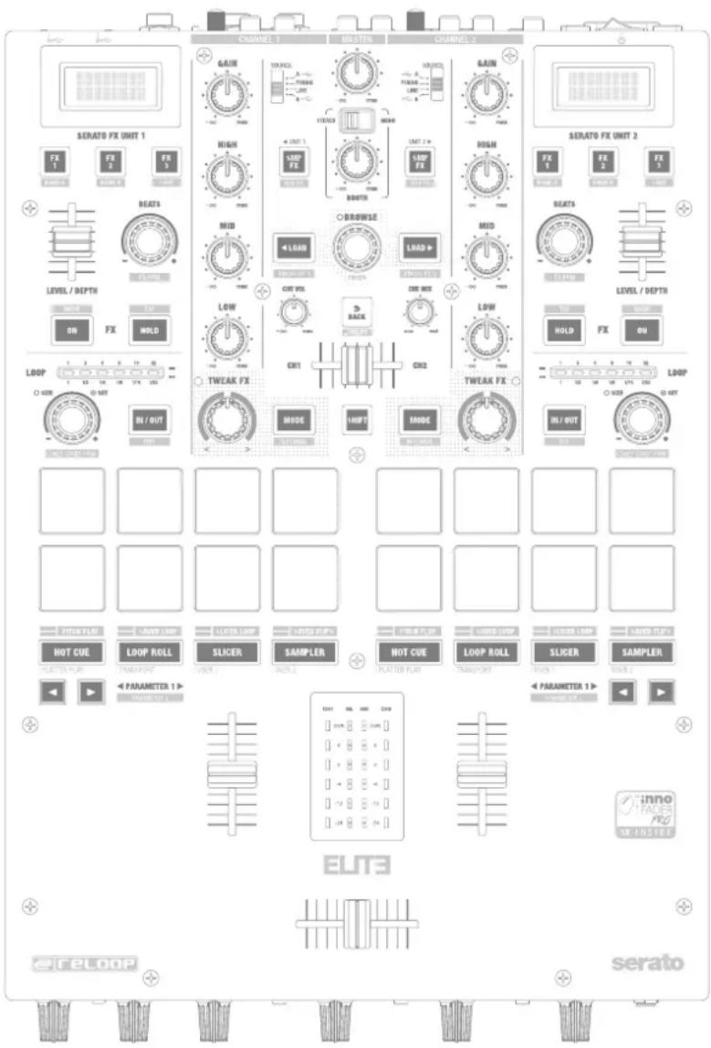
User Interface
Front-Side
Backside
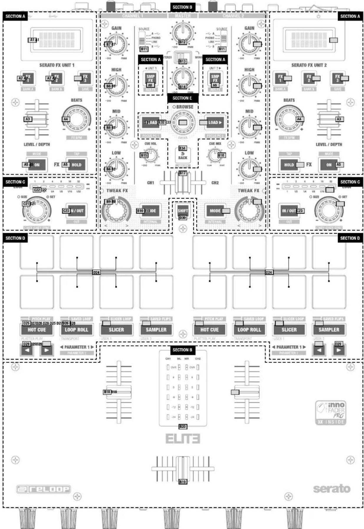
1.2 Designations
A .Serato DJ Pro Effect Section
B ......Mixer Section
C...........................Loop Section
D Performance Mode Section
E.........Navigation Section
F. Front Control Section
G .........Connections
A Serato DJ Pro Effect Section
AO1. .Effect Information Display
A02.....Effect Select Buttons
A03.......Level/Depth Slider
A04. Beat Length Select Encoder
A05. ....Effect On/Off Buttons
A06....Sampler/Aux Effect On/Off Button
B Mixer Section
B07. ..Gain
B08. .EO
B09. Tweak FX
B10. Tweak FX Mode
B11. Input Select
B12....Master Volume
B13. Booth Mono/Stereo Switch
B14. Booth Volume
B15. ...... Headphone Volume
B16. ...Cue Mix
B17. ...Cue Channel Select
B18. Channel Line Fader
B19. ......... Crossfader
B20. VU-Meter
C Loop Section
C21. .........Loop Encoder
C22....Loop Length Bar
C23. Manual Loop Button
D Performance Mode Section
D24. Performance Pads
D25-D28...Performance Mode Buttons
D29. Parameter Control Buttons
D30. ......Shift Button
E Navigation Section
E31....... Navigation Encoder
E32/33....Load Buttons
E34. Back Button
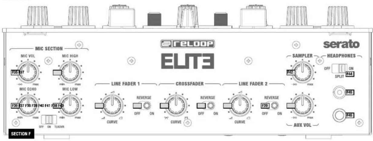
F Front Controls
F35. Microphone Volume Knob
F36. Microphone Effect Echo Knob
F37. Microphone EQ
F38. Linefader Curve Knob
F39....Linefader Reverse Switch
F40. .........Crossfader Curve Knob
F41. ......... Crossfader Reverse Switch
F42. ......... Sampler Volume Knob
F43. Aux Volume Knob
F44. ...... Headphone Split Switch
F45. ...Headphone Outputs
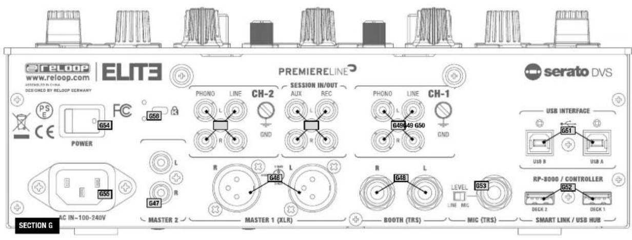
G Connections
G46. XLR Main Outputs
G47. RCA Main Outputs
G48. .......Booth Jack Outputs
G49. ......RCA Inputs
G50. RCA Session In/Out
G51. Dual USB 2.0 Ports
G52. .RP-8000 MK2/
MIDI Controller Connections
G53. Microphone Jack Input
with Level Control
G54.....Power Switch
G55. .......Mains Power Connection
G56. .Kensington Lock
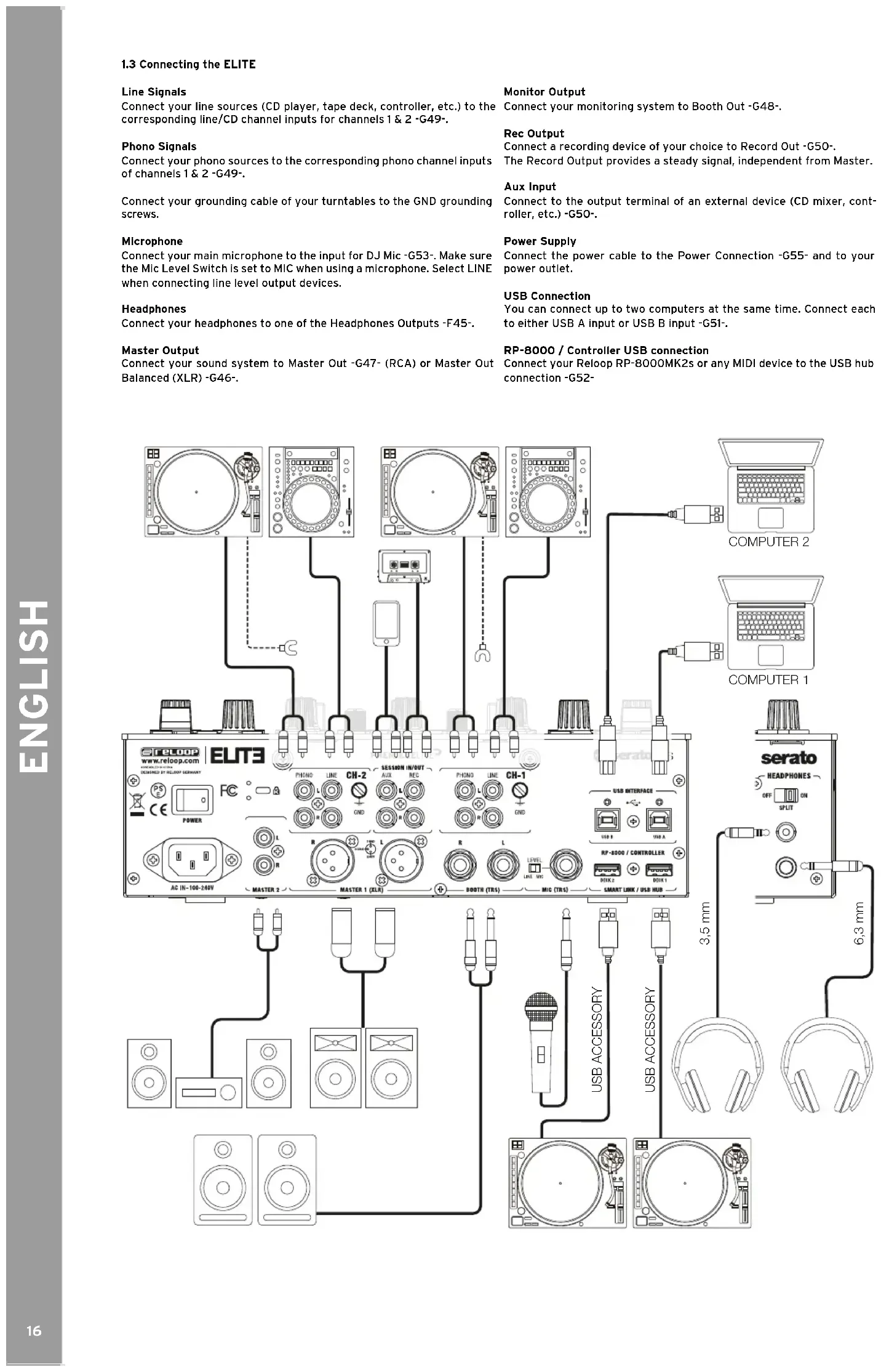
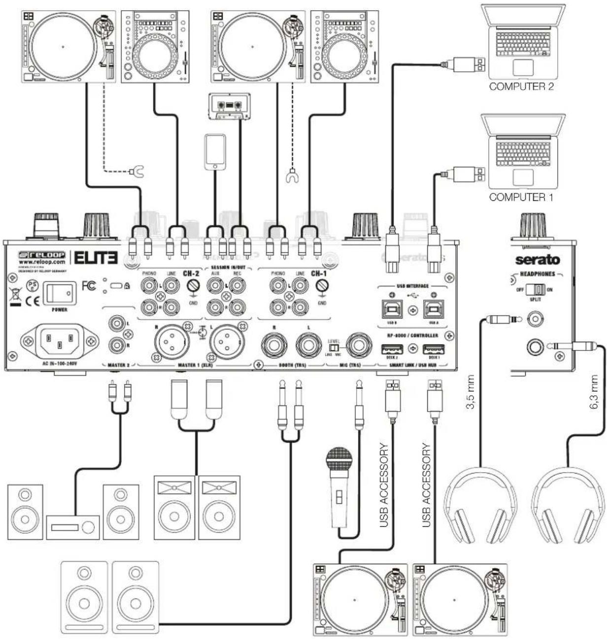
1.3 Connecting the ELITE
Line Signals
Connect your line sources (CD player, tape deck, controller, etc.) to the corresponding line/CD channel inputs for channels 1 & 2 -G49-.
Phono Signals
Connect your phono sources to the corresponding phono channel inputs of channels 1 & 2 -G49-.
Connect your grounding cable of your turntables to the GND grounding screws.
Microphone
Connect your main microphone to the input for DJ Mic-G53-. Make sure the Mic Level Switch is set to MIC when using a microphone. Select LINE when connecting line level output devices.
Headphones
Connect your headphones to one of the Headphones Outputs -F45-.
Master Output
Connect your sound system to Master Out -G47- (RCA) or Master Out Balanced (XLR)-G46-.
Monitor Output
Connect your monitoring system to Booth Out-G48-
Rec Output
Connect a recording device of your choice to Record Out -G50-.
The Record Output provides a steady signal, Independent from Master.
Aux Input
Connect to the output terminal of an external device (CD mixer, controller, etc.) -G50-.
Power Supply
Connect the power cable to the Power Connection -G55- and to your power outlet.
USB Connection
You can connect up to two computers at the same time. Connect each to either USB A input or USB B input -G51-.
RP-8000/ControllerUSBconnection
Connect your Reloop RP-8000MK2s or any MIDI device to the USB hub connection -G52
2. OPERATION
Power On
After all connections have been carried out, you can turn on the device via the ON/OFF Switch -G54.
Signal Input Select
Via the Signal Input Select Switch -B11- you can select between line, CD, phono and USB sources for channels 1-2. Please observe the captions of the single signal input switches.
Gain
Via the Gain Dials -B07- you can adjust the input volume for channels 1 & 2.
Make sure that peak signals are within the green range of the LED indicator -B20-.
Use the Mic Level Dial -F35-, to adjust the DJ microphone and Line Input, respectively.
Equalizer
With the 3-Band Equalizers -B8- you can adjust low, mid and high frequencies for channels 1 & 2.
Via the 2-Band Equalizer -F37- you can adjust low and high frequencies for the microphone channel.
TweakFX
Channels 1 & 2 offer hardware-dedicated effects which can be assigned to the TweakFX Switch -B09-. The ELITE offers the following effects: Filter, BitCrush, Whitenoise and Flanger. Switching through them can be done by clicking the Mode Button -BIO-. In the 12 o'clock position, the filter is turned off.
Linefader
The Linefaders-B18- are used to adjust the output volume for channels 1 & 2.
The Linefader's curve can be adjusted with the help of the Linefader Curve Dial -F38-.
In the 12 o'clock position the curve is linear. When switching the Reverse Switch -F39-, the linefader signal can be reversed.
Crossfader
With the Crossfader -B19- it is possible to switch between the left and right crossfader channel. The crossfader's curve can be adjusted via the Crossfader Curve Dial -F40-. By turning counter-clockwise, the crossfader becomes "sharp", namely good for scratching and cutting.
By turning clockwise, the crossfader becomes "smooth", namely good for long mixes.
DJ Mic
By using the Mic Switch you can activate the microphone and, as the case may be, the talkover effect. This results in the suppression of the remaining channels via the microphone signal (Active Ducking Technology).
In the OFF position the channel is turned off. ON activates the microphone's signal, TALKOVER activates the talkover function (Active Ducking Technology).
Monitoring
With the Cue Channel Select Slider -B17- you can select the input channel(s) that you wish to monitor via your headphones.
With Cue Mix -B16- you can fade between the channel(s) selected via the Cue Channel Select Slider and the master signal. In the CUE position you will only hear the monitoring channels selected; in MASTER position you will only hear the master signal.
You can mix the signals stepplessly. This way you can simulate a mix via your headphones. With the Headphones Input Volume Dial -B15- you can adjust your headphones' volume level.
Master Section
By using the master dial you can adjust the master output volume.
Make sure that the Master Signal's LED -B20- is only visible in the yellow range.
Adjust the booth output volume via the Booth Volume Dial-B14.
Via the Mono/Stereo Switch -B13- you can select the booth output's output mode.
NOTE! Rec Output is not affected by the Volume Dials' position.
Under item "Setup Utility MASTER" you can find further information and setting options.
3. SETUP-UTILITY
3.1 Menu Structure
Via the setup menu it is possible to adapt basic system settings to your individual needs. To access the setup menu, make sure the device is turned off. Press and hold Shift -D30- and the Back Button -E34- and turn on the device. The Effect Display will read MASTER. By turning the Navigation encoder -E31- you can access the various menu items. When you have found your desired menu item, press the encoder. Now you can adjust the menu Item by turning the encoder. Via the Back Button you can return to the previous setup.
3.2 Menu Items
MASTER OUTPUT
Select between stereo and mono.
If your sound system only disposes of mono mode, it is recommended to activate mono, to make sure that the same signal is sent to all speakers.
MASTERLIMITER
The limiter reduces the output signal.
Select between a reduction of 0dB, -3dB, -6dB -12dB.
In order not to exceed a certain volume level, it is helpful to limit the maximum output beforehand.
FADER SETTINGS
Here you can adjust the cut-In settings for crossfader and channel faders in a range of 0.0mm and 3.2mm in 0.1mm steps.
FX FADER CONTROL
Selects whether the Effect Level/Depth slider -A03- controls effect slot 1 only or effect slots 1-3 simultaneously.
USB OUT SETTINGS
It is possible to send different input signals from the mixer via the USB Port to your computer.
| USB Sub Value Type Channel Control Vakeu MIDI Out Request | ||||||||
| OUT 1+2 | PHONO Control Tone | SW | CC | N | 32 | 0 | X | X |
| CD Control Tone | SW | CC | N | 32 | 1 | X | X | |
| CF A | SW | CC | N | 32 | 2 | X | X | |
| CF B | SW | CC | N | 32 | 3 | X | X | |
| MIC | SW | CC | N | 32 | 4 | X | X | |
| Aux | SW | CC | N | 32 | 5 | X | X | |
| Post Fader Deck 1 | SW | CC | N | 32 | 6 | X | X | |
| None | SW | CC | N | 32 | 7 | X | X | |
| OUT 3+4 | PHONO Control Tone | SW | CC | N | 32 | 0 | X | X |
| CD Control Tone | SW | CC | N | 32 | 1 | X | X | |
| CF A | SW | CC | N | 32 | 2 | X | X | |
| CF B | SW | CC | N | 32 | 3 | X | X | |
| MIC | SW | CC | N | 32 | 3 | X | X | |
| Aux | SW | CC | N | 32 | 4 | X | X | |
| Post Fader Deck 2 | SW | CC | N | 32 | 5 | X | X | |
| None | SW | CC | N | 32 | 6 | X | X | |
| OUT 5+6 | REC OUT | SW CC R | F 0 X X | |||||
| CF A | SW | CC | R | 7F | 1 | X | X | |
| CF B | SW CC R | F 2 X X | ||||||
| MIC | SW | CC | R | 7F | 3 | X | X | |
| Aux | SW | CC | R | 7F | 4 | X | X | |
| Post Fader Deck 1 | SW | CC | R | 7F | 5 | X | X | |
| Post Fader Deck 2 | SW | CC | R | 7F | 6 | X | X | |
| None | SW | CC | R | 7F | 7 | X | X | |
FILTER RESO
The filter's response curve can be adjusted. In order to increase the response, simply increase the percentage value.
TLKOVRL (Talkover Level)
Determines how much the signal will be suppressed by the mic signal. -6dB, -12dB, -18dB, -24dB
ISO XOVR (Isolator Crossover)
Adapt the EQ's bass and high crossover frequencies to your requirements.
SHIFT LOCK
If active, the Shift Button needs to be toggled instead of being held to switch to the shift layer.
VELOCITY SENS
If active, Pads -D24- are velocity sensitive.
PAD SENS (Pad sensitivity)
Selects the sensitivity of the Performance Pads -D24- in four steps. "ULTRA" means very low pressure is needed while in "LOW" Pads need to be pressed with higher pressure.
MIC BTH (Mic Booth)
ON: The mic signal is also sent via the booth output.
OFF: The mic signal is not sent via the booth output. If the case may be, the OFF setting can prevent feedback.
MIC LOW CUT
When turned on, low frequencies (f<80Hz) will be cut off.
AUX GAIN COMPENSATION
You can increase the Aux Input's input level in order to achieve louder playback of sources with a weaker signal (e.g. smartphones).
LED CHECK
All LEDs will be activated in order to check their functionality.
FACTORY RESET
If you have adjusted a setting that cannot be reversed, you can select this item to bring all settings back to default.
FIRMWARE UPDATE
In order to carry out a firmware update, connect your ELITE via USB -51- to a computer and make sure that your ELITE is turned off via the ON/OFF Switch -54-. Scroll to FW UPDATE and confirm this item by pressing the Time Encoder. Please regularly check www.reloop.com for ELITE firmware updates. Please make sure that the loaded firmware is compatible with your device.
- Download the corresponding update package from the Reloop ELITE product site and open it.
- Open the program "ReloopFirmwareUpdate.jar".
- Select the new firmware file by clicking "Open File" and selecting the included *.bin file.
- Click "Start >". The update will start now.
- After a successful update turn off the Reloop ELITE.
If you feel uncertain about this procedure, let your specialized dealer carry out the update.
ABOUT
Shows the current firmware version.
EXIT
The mixing console starts anew.
4. SERATO DJ PRO DVS CONTROL
ELITE is a Serato DJ Pro and DVS enabled mixer and does not require further licenses for activation. Make sure that the mixer is connected via USB to your computer and that you run the latest Serato DJ Pro version (www.serato.com).
4.1 Functionality
Navigation Section
By turning the Navigation Encoder, it is possible to browse the respective active playlist view. By pressing the Load Buttons, the selected track will be loaded to the right deck.
Provided that 2 Serato DJ Pro instances are connected to ELITE, the Navigation Section can be assigned to one instance at a time. Therefore, only one computer can access the navigation section at a time, which prevents you from accidentally loading a track. By pressing Shift+Load1 the assignment will be carried out for USB Port A and by pressing Shift+Load2 the assignment will be carried out for USB Port B. The assignment can be carried out automatically or manually, as described,
Loop Section
By turning the Loop Encoder, you can adjust the loop's length. The currently active length is additionally shown in the Loop Length Bar. By pressing the encoder, auto loop will be set, according to the set length. Via the Loop In/Out Button it is possible to set a manual loop. In case no active loop is set, pressing once will result in setting a loop starting point. The button will start blinking. By pressing again, you will set the loop ending point. The loop is now active and the button will be constantly lit. If a loop is already active, the loop starting point can be adjusted by pressing the Loop In/Out Button. If you wish to adjust the loop ending point, press Shift+Loop In/Out.
Serato DJ Pro offers the possibility to manipulate the tone pitch of a track. By pressing and turning Shift+Loop Length Encoder, the tone pitch will be adjusted. By pressing and holding Shift+Loop Encoder, the tone pitch will be matched, according to the respective opposite deck.
NOTE! For tone pitch manipulation the Serato Expansion Pack "Pitch 'N Time" is necessary.
Performance Mode Section
It is possible to set 12 different modes for the 8 touch-sensitive pads:
Hot Cue Mode:
Triggers the 8 available cue points per deck.
The hot cue colours can be adjusted to one's requirements in the software and the pads will shine correspondingly. Parameter knobs will carry out Serato "Flip" functions: Play, Record, Loop, On/Off.
Loop Roll Mode:
Each pad (de-)activates a loop roll, when the pad is being held. A loop length between 1/32 - 4/1 is assigned to each deck.
Slicer Mode:
When slicer is active, a specified section will be split into 8 even parts. These 8 sliced parts will be spread across the corresponding performance pads. When the playhead reaches the end of a section, it will move beyond the section and create a new one.
Sampler Mode:
Pads 1-6 trigger the 6 available sample slots. Shift+Pad stops the sample. Via the parameter buttons you can switch between banks A, B, C and D. Adjust the volume via the Sample Volume Dial.
Pitch Play Mode:
In combination with Pitch 'N Time, it is possible to play back your cues in different tone keys. There are 3 tone keys at your disposal. In order to switch between these, press the left or right PARAM 1 Button. The pad with the fundamental note is lit white; here the cue point will be played back in its original tone key. When in Pitch Play Mode, your cue point will be played back in various tone keys by playing the pads. To select another hot cue point, hold shift and simultaneously press another pad (hot cue).
Saved Loop Mode:
It is possible to store up to 8 loops. Each pad corresponds to a loop slot. To store a loop, set an auto loop and press a pad slot. By pressing again, the loop will be deleted.
Trigger the loop by simultaneously pressing the shift button and a pad.
Slicer Loop Mode:
If slicer is active, a specific section will be divided into 8 even parts. These 8 sliced parts will be spread across the corresponding performance pads. When the playhead reaches the ending of a section, it will move back to the beginning of the section and play back the loop again.
Saved Flips Mode:
Up to 8 saved flips can be displayed, which can be activated by pressing. Shift+Pad jumps directly to the respective flip and will start it as well.
Effect Section:
Reo t t t t t t t t t t t t t t t t t t t t t t t t t t t t t t t t t t t t t t t t t t t t t t t t t t t t
It is possible to read the following information on the effect displays:
- Multi effect mode: the three respectively loaded effects for slots 1-3 in abbreviated spelling
- Extended effect mode: the loaded effect in abbreviated spelling
- The selected effect bank's BPM
- Effect beat length
Via the effect buttons FX1-3 the assigned effect slot will be armed, but not activated immediately. If one of these buttons lights up, the effect will only be activated after FX On or FX HOLD has been activated. By holding one of these buttons while at the same time turning the Beat Length Encoder, an effect from the available list can be selected. Serato DJ Pro also offers the possibility to carry out individual effect settings and store these as 2 presets. In order to activate these, press Shift+F1 or Shift+F2, respectively. By pressing Shift+FX3 the current effect bank A selection will be stored.
The effect's intensity can be adjusted via the Effect Dial. Please consider the settings in the firmware menu FADER SETTINGS.
The Effect Bank's BPM - which usually corresponds to the loaded track's BPM - can be set manually by tapping Shift+FX HOLD. The display will show the changes. For more precise BPM settings, it is possible to adjust the BPM value in increments of one by pressing Shift and turning the Beat Length Encoder.
By pressing Shift+FX On, it is possible to switch between the effect bank views "Advanced" and "Multi". Due to the available effect routing architecture, the Serato Sampler's and aux input's audio signals can be contained in the effect loop. The signal can only be assigned to one effect bank.
4.2 Driver Installation
The Reloop ELITE is a class compliant device for Mac OS X, but for Windows a driver is necessary. Please make sure that the driver installation is complete before using Serato DJ Pro.
Mac
No driver necessary.
Windows
Download the driver via our website: www.reloop.com
Double click the .exe file to begin the installation and follow the instructions on screen. Make sure to re-start the mixer after the installation.
4.3 Connections
Should you prefer turntables for DVS control, connect them to the phono inputs of channels 1 and 2. If you use CD players, please connect them to the corresponding LINE Inputs.
Put the respective input switches to either USB A or USB B.
In Serato DJ Pro open the settings and go to the AUDIO tab. Depending on the connected devices, please select the corresponding DVS source in the software:
PHONO: turntables
CDJs: CD players
Custom: depending on the settings in the USB OUT firmware menu, you can also use different DVS sources (PHONO & CDJs)
5. TECHNICAL SPECIFICATIONS
Frequency response: 20 Hz - 20 kHz
Inputs: 2x phono RCA
2x line RCA
AUXRCA
Mic/line TRS
2xSmart Link USB ports (type A)
2x USB ports (type B)
Outputs: Master XLR (balanced)
Master RCA (unbalanced)
Booth TRS (balanced)
Rec RCA (unbalanced)
Headphones 6.3/3.5 mm jack
EQ range at 70 Hz, 1 kHz, 13 kHz: -45 dB (total kill)/-90/+12 dB
EQ range Mic at 100 Hz, 10 kHz: -26 dB/+12 dB
Accessories included: Full version of Serato DJ Pro with DVS Expansion Pack, 2x Serato Control Vinyls with NoiseMap technology, USB cable, power cord, operating instructions and 90 days BPM Supreme membership
SOMMAIRE
A Section effect Serato DJ Pro 25
B Section Mixer. 25
D Section mode Performance 25
E Section de navigation. 25
RP-8000/ControllerUSBconnection. 26
- Utilisation 27
TLKOVRL (Talkover Level) 28
ISO XOVR (Isolator Crossover) 28
SHIFT LOCK 28
VELOCITY SENS 28
MIC BTH (Mic Booth) 28
MIC LOW CUT 28
AUX GAIN COMPENSATION 28
LED CHECK 28
FACTORY RESET 28
Section Navigation 29
Section Boucle 29
Section Mode Performance 29
Mode Hot Cue 29
Mode Loop Roll 29
Mode Slicer 29
Mode Sampler 29
Mode Pitch Play 29
Mode Saved Loop 29
Mode Slicer Loop 29
Mode Saved Flips 29
Section d'effets 30
D ....Section mode Performance
E ....Section de navigation
A Section effect Serato DJ Pro
A01. .......Affichage Informations effet
A04....Encodeur selection Beat Length
A05....Touches marche/arret effet
D Section mode Performance
RP-8000/ControllerUSBconnection
| USB Sub Value Type Channel Control Value MIDI Out Request | ||||||||
| OUT 1+2 | PHONO Control Tone | SW | CC | N | 32 | 0 | X | X |
| CD Control Tone | SW | CC | N | 32 | 1 | X | X | |
| CF A | SW | CC | N | 32 | 2 | X | X | |
| CF B | SW | CC | N | 32 | 3 | X | X | |
| MIC | SW | CC | N | 32 | 4 | X | X | |
| Aux | SW | CC | N | 32 | 5 | X | X | |
| Post Fader Deck 1 | SW | CC | N | 32 | 6 | X | X | |
| None | SW | CC | N | 32 | 7 | X | X | |
| OUT 3+4 | PHONO Control Tone | SW | CC | N | 32 | 0 | X | X |
| CD Control Tone | SW | CC | N | 32 | 1 | X | X | |
| CF A | SW | CC | N | 32 | 2 | X | X | |
| CF B | SW | CC | N | 32 | 3 | X | X | |
| MIC | SW | CC | N | 32 | 1 | X | X | |
| Aux | SW | CC | N | 32 | 5 | X | X | |
| Post Fader Deck 2 | SW | CC | N | 32 | 6 | X | X | |
| None | SW | CC | N | 32 | 7 | X | X | |
| OUT 5+6 | REC OUT | SW CC R | F 0 X X | |||||
| CF A | SW | CC | R | 7F | 1 | X | X | |
| CF B | SW CC R | F 2 X X | ||||||
| MIC | SW | CC | R | 7F | 3 | X | X | |
| Aux | SW | CC | R | 7F | 4 | X | X | |
| Post Fader Deck 1 | SW CC R | F 5 X X | ||||||
| Post Fader Deck 2 | SW CC R | F 6 X X | ||||||
| None | SW | CC | R | 7F | 7 | X | X | |
FILTER RESO
TLKOVRL (Talkover Level)
Section Mode Performance
2x Smart Link ports USB (type A)
2x ports USB (type B)
RP-8000/ControllerUSBconnection
| USB Sub Value Type Channel Control Value MIDI Out Request | ||||||||
| OUT 1+2 | PHONO Control Tone | SW | CC | N | 32 | 0 | X | X |
| CD Control Tone | SW | CC | N | 32 | 1 | X | X | |
| CF A | SW | CC | N | 32 | 2 | X | X | |
| CF B | SW | CC | N | 32 | 3 | X | X | |
| MIC | SW | CC | N | 32 | 4 | X | X | |
| Aux | SW | CC | N | 32 | 5 | X | X | |
| Post Fader Deck 1 | SW | CC | N | 32 | 6 | X | X | |
| None | SW | CC | N | 32 | 7 | X | X | |
| OUT 3+4 | PHONO Control Tone | SW | CC | N | 32 | 0 | X | X |
| CD Control Tone | SW | CC | N | 32 | 1 | X | X | |
| CF A | SW | CC | N | 32 | 2 | X | X | |
| CF B | SW | CC | N | 32 | 3 | X | X | |
| MIC | SW | CC | N | 32 | 1 | X | X | |
| Aux | SW | CC | N | 32 | 5 | X | X | |
| Post Fader Deck 2 | SW | CC | N | 32 | 6 | X | X | |
| None | SW | CC | N | 32 | 7 | X | X | |
| OUT 5+6 | REC OUT | SW | CC | R | 7F | 0 | X | X |
| CF A | SW | CC | R | 7F | 1 | X | X | |
| CF B | SW | CC | R | 7F | 2 | X | X | |
| MIC | SW | CC | R | 7F | 3 | X | X | |
| Aux | SW | CC | R | 7F | 4 | X | X | |
| Post Fader Deck 1 | SW | CC | R | 7F | 5 | X | X | |
| Post Fader Deck 2 | SW | CC | R | 7F | 6 | X | X | |
| None | SW | CC | R | 7F | 7 | X | X | |
TLKOVRL (Talkover Level)
Subject to alterations.
Illustrations similar to original product.
Misprints excepted.