
DSP 44 K - Receiver LD Systems - Free user manual and instructions
Find the device manual for free DSP 44 K LD Systems in PDF.

User questions about DSP 44 K LD Systems
0 question about this device. Answer the ones you know or ask your own.
Ask a new question about this device
Download the instructions for your Receiver in PDF format for free! Find your manual DSP 44 K - LD Systems and take your electronic device back in hand. On this page are published all the documents necessary for the use of your device. DSP 44 K by LD Systems.
USER MANUAL DSP 44 K LD Systems
In the event of misuse, improper use, or negligent handling of the software, the developer (Adam Hall GmbH) shall not be liable for any damage to devices of any kind or to any software; this includes personal injury.
1. INTRODUCTION
The LD OCS software (Online Control System) serves to configure LD DSP44K and DSP45K DSP power amps, load current LD speaker presets, and to create and manage custom speaker and amp presets in 80 storage locations each. At the standard level, the user can only load speaker presets (e.g. LD speaker presets) and create and manage amp presets (see Section 10. CREATING AND ADMINISTERING AMP PRESETS). Creating and administering the user's own speaker presets is done at the password-protected user level (see Section 9. CREATING AND ADMINISTERING CUSTOM). The software is compatible with Windows 7, 8, and 10, and uses either a USB interface at version 2.0+ or an Ethernet interface for purposes of data connection.
2. SOFTWARE INSTALLATION
Download the LD_OCS_Setup.exe file from the product page at WWW.LD-SYSTEMS.COM and install it to a Windows PC.
3. CREATING CONNECTION VIA USB
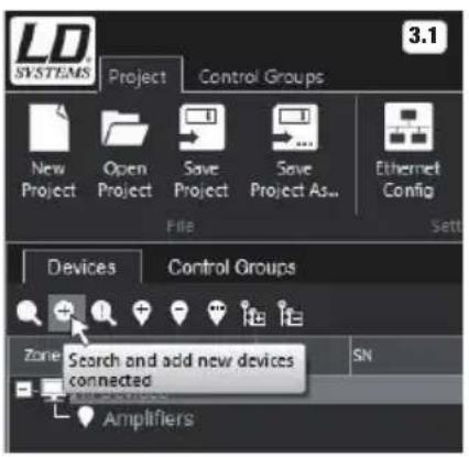
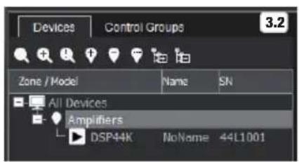
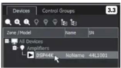
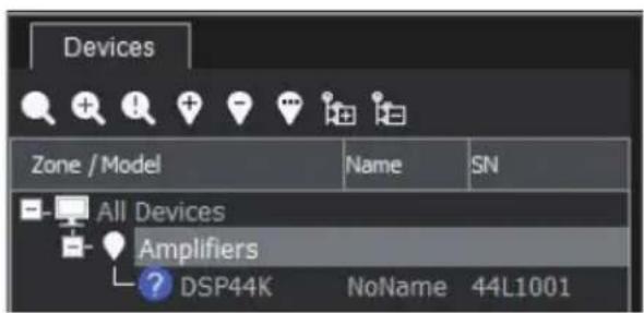
Connect the USB port on the LD DSP44K or DSP45K power amp using a suitable USB cable (USB 2.0, USB-A to USB-B) with the USB port on your PC, and switch on the power amp (the driver may take a moment to install, ATTENTION: A maximum of 1 power amp may be connected via USB). Now start the LD OCS software and click on the magnifying glass symbol with a plus sign (Fig. 3.1) under Devices. The connected power amp will now be displayed under Amplifiers with the model number, name, and serial number of the amplifier (Fig 3.2). Now double click on the power amp model to synchronize the current settings of the power amp with the software (Fig 3.3.).
4. CREATING CONNECTION VIA ETHERNET
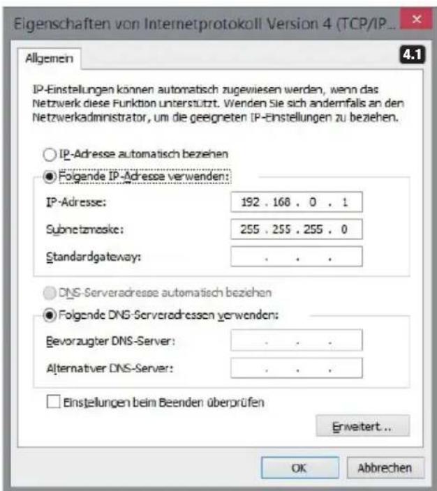
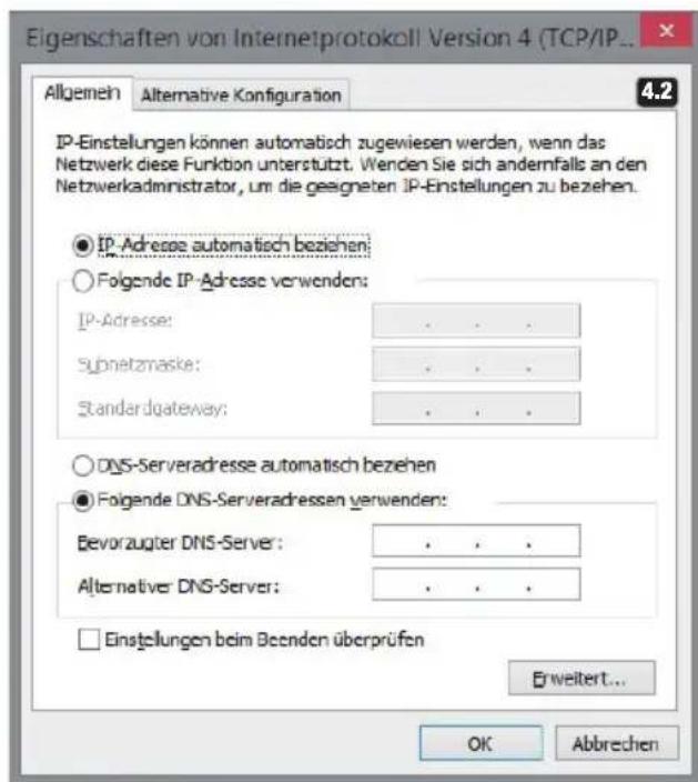
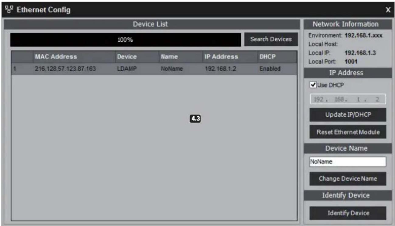
Connect the Ethernet port on the LD DSP44K or DSP45K power amp using a suitable Ethernet cable with the Ethernet port on your PC, and switch on the power amp. If you would like to connect and manage 2 or more LD DSP44K or DSP45K power amps with your PC, please use an Ethernet switch and set a unique IP address for each power amp (e.g. 192.168.0.100, 192.168.0.101, etc.). You can manually set the IP address of the power amp on the device itself or in the OCS software under Ethernet Config. The IP address of the LD DSP44K or DSP45K power amp is set to 192.168.0.100 by the manufacturer, meaning another IP address must be used in the PC system settings under Internet Protocol Properties Version 4 (TCP/IPv4), in this case, 192.168.0.1 (Fig. 4.1), for example. IP settings can be automatically applied (Fig. 4.2), if the network supports this function (e.g. network route). Start the OCS software and ensure that DHCP is enabled under Ethernet Config (DHCP Enabled, Fig. 4.3), also click the button for Use DHCP and the button Update IP/DHCP. In addition, you can search for a device in the Ethernet Config window
(Search Devices), change the IP address of a power amp (if DHCP is not used, enter numbers into the input field and click Update IP/ DHCP), reset the Ethernet module of the power amp (Reset Ethernet Module), and assign a name to the power amp (enter name into the input field under "Device Name" and click Change Device Name). To identify a power amp, click on the desired power amp in the device list, then click on Identify Device, the power amp name and IP address will be shown on the device display for a short time.
Note: In certain cases, there may be a conflict between the Ethernet interface and the WLAN interface, resulting in the OCS software not being able to detect the Ethernet interface. In this case, disable the WLAN interface on your computer.
Close the Ethernet Config window and then click on the magnifying glass symbol with a plus sign (Fig. 3.1) under Devices. The connected power amp will now be displayed under Amplifiers with the model number, name, and serial number of the amplifier (Fig 3.2). Now double click on the power amp model to synchronize the entire library stored to the power amp with the software (Fig 3.3.). The synchronization process will take several seconds. If group parameters are enabled, a subsequent window will ask whether the group parameters are to be sent from the OCS to the power amp ("Do you want to synchronize them?"). Generally, this request should be confirmed with "Yes" (click on "Yes"). You can find more information on control groups and their functions in Section 11. CONTROL GROUPS of these instructions.
5. PREFERENCES
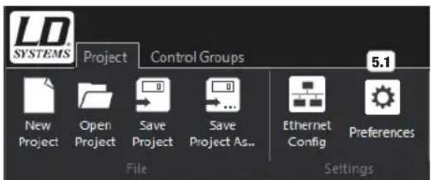
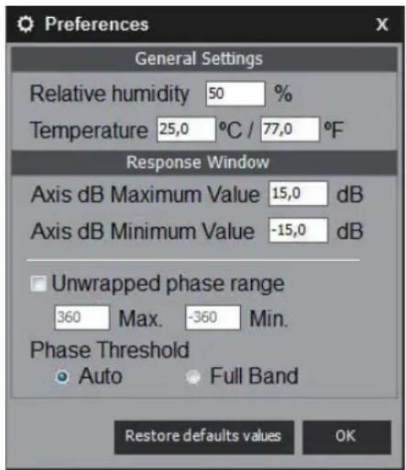
Project - Preferences - Click on the button Preferences (no. 5.1) to enter general settings like relative humidity and ambient temperature (to determine delay) and to specify the minimum and maximum value in the Frequency Response window, to enable Unwrapped phase range, and to switch the phase threshold from Auto to Full Band and vice versa. Click on Restore default values to restore these settings to the factory default settings the next time the software starts. These settings are stored when saving a project file.
6. OVERVIEW WINDOW
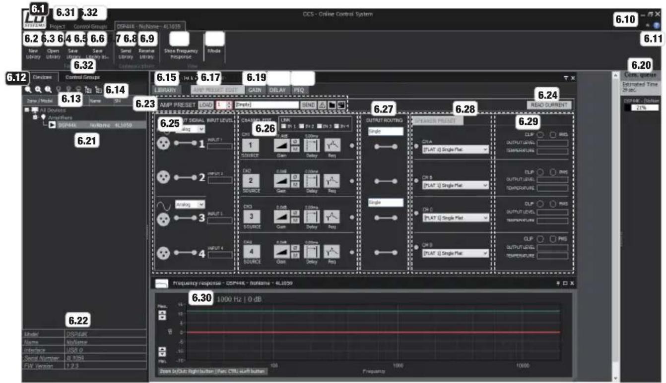
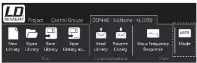
6.1 LD SYSTEMS - Click this button to access the software information window (About application) and the switch-off button (Exit).
6.2 New Library - Creates a new preset library. The currently loaded amp and customer speaker presets will be removed from the preset lists.
6.3 Open Library - Loads the preset library saved to the PC. Click, select library, and open.
6.4 Save Library - Saves a preset library to the PC. Click, select location, assign name, and save.
6.5 Save Library as - Saves a preset library to the PC under a new name. Click, select location, assign name, and save.
6.6 Send Library - Sends and saves the currently loaded library to the power amp.
6.7 Receive Library - Load a preset library from the power amp's storage device.
6.8 Show Frequency Response - Displays or hides the frequency response (6.30).
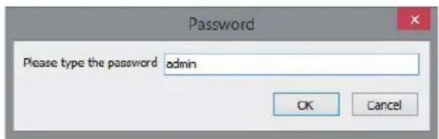
6.9 Mode - Sign in using the password (= admin) in order to create custom speaker presets.
6.10 slides or shows the menu bar.
6.11 6 opens the software information window.
6.12 Clear, search and add all devices connected - Removes devices, searches for and adds connected devices.
Search and add new devices connected - Searches for and adds connected devices.
Reconnect all lost devices - Recreates interrupted connections (e.g. for a power outage).
6.13 Add New Zone -Adds new zone.
Delete selected Zone - Deletes selected zone.
Rename selected Zone - Renames selected zone.
6.14 Expand all tree - Displays the structure tree.
Collapse all tree - Collapses the structure tree.
6.15 LIBRARY - Click this button to access the amp preset, custom speaker preset, and LD speaker preset libraries.
6.16 AMP PRESET EDIT - Click this button to open the amp preset overview window.
6.17 GAIN - Click this button to edit the gain, polarity, and muting in Amp Preset.
6.18 Delay - Click this button to edit the signal delay in Amp Preset.
6.19 PEQ - Click this button to edit the 12-band equalizer in Amp Preset.
6.20 Com. queue - Displays the status when synchronizing the power amp with the software.
6.21 Devices - Lists the connected and added devices.
6.22 Information on the selected device (model, serial numbers, name, IP address, and firmware version).
6.23 AMP PRESET
LOAD - Select an amp preset from the amp preset library using the arrow icons and load it by clicking on LOAD (preset name in the window to the right next to the arrow icons).
SEND - Send an amp preset to the power amp's storage device and load it.
- Resets the settings in Amp Preset to begin creating a new amp preset.
The previously loaded amp preset will not be removed from the amp preset library.
- Loads an amp preset stored on the PC.
- Saves an amp preset to the PC.
6.24 READ CURRENT - Synchronizes the amp preset currently loaded to the power amp with the software.
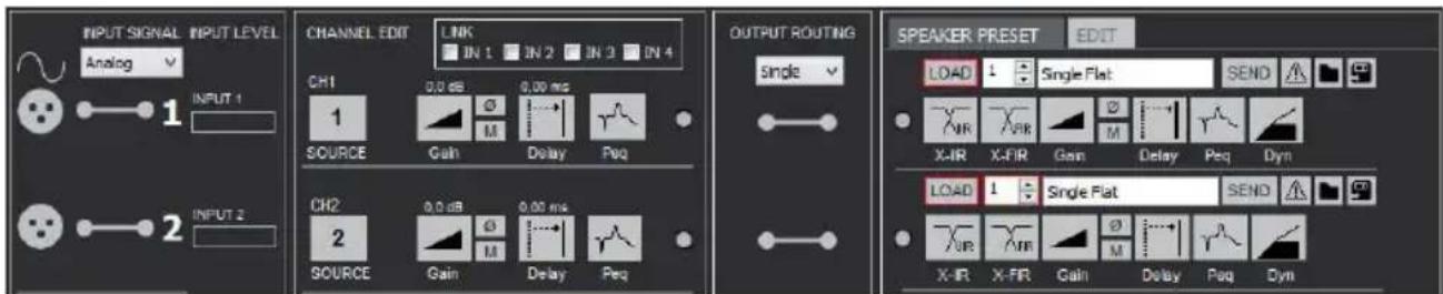
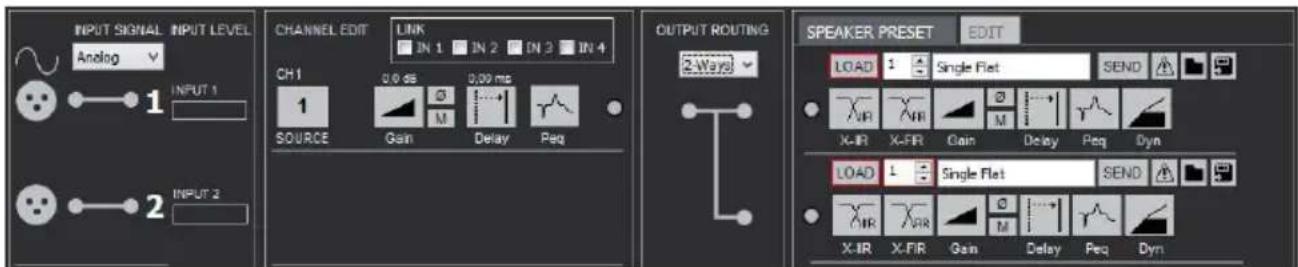
6.25 INPUT SIGNAL - (DSP44K only) Click on the collapsible menu to select an analog physical signal input (XLR) or DANTE (RJ45). This setting applies to Input 1 and 2 or 3 and 4. The setting is not saved to an amp preset.
INPUT LEVEL - Displays the levels of inputs 1 to 4.
6.26 CHANNEL EDIT
SOURCE - Sets the signal source for channels 1 to 4.
LINK - Before editing, you can link the channels whose settings are to be the same (check the box).
The settings must therefore only be applied to one channel and will be automatically applied to linked channels.
Gain - Click this button to open the editing window for the signal gain. The polarity and channel muting (Mute) can also be edited here.
- Inverts the polarity of the channel.
M - Mutes the channel.
Delay - Click this button to open the editing window for the signal delay. The time delay is displayed in meters (m), feet (feet), and milliseconds (ms).
Peq - Click this button to open the editing window for the 12-band parametric equalizer.
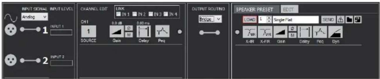
6.27 OUTPUT ROUTING - Graphical display of output routing (single, 2-way, bridge).
6.28 SPEAKER PRESET - Selection window for the speaker presets saved to the custom speaker preset and LD speaker preset libraries.
6.29 DISPLAY FIELDS
CLIP - The CLIP display field will illuminate when the corresponding power amp channel is being operated
at the limit threshold. Brief illuminations are not critical. In order to protect the system, an excessive signal level
is smoothed by the integrated limiter. If the CLIP display illuminates for a longer time or permanently, reduce the volume level.
PMS - The PMS (Power Management System) is an electronic protection system that permanently
monitors and regulates the power amp parameters in order to ensure that only the power necessary for safe and secure operation is drawn from the power supply (monitors the signal input, capacity, temperature, current). The PMS display illuminates in the following situations:
- The internal temperature rises close to the limit at which the automatic switch-off function would be activated to prevent the system from overheating due to unfavorable working conditions.
In this case, the system takes control and reduces the power supply to a level at which the power amp would not be switched off in this situation.
- Excessive power consumption. This situation applies only under laboratory conditions, in endurance tests with sinusoidal audio signals with dummy loads, or in prolonged acoustic feedback conditions. Here, the system intervenes in order to avoid damage to the speaker and to prevent the primary breaker from triggering or the electric fuses from blowing out.
OUTPUT LEVEL - Shows the level of the output channels A to D.
TEMPERATURE - Shows the operating temperature of the output levels A to D.
6.30 Frequency Response - Graphic depiction of the frequency response.
6.31 Project - Create and manage projects (New Project, Open Project, Save Project, Save Project as).
6.32 Control Groups - Create and manage control groups (see Section 11. CONTROL GROUPS).
7. MANAGING POWER AMPLIFIERS
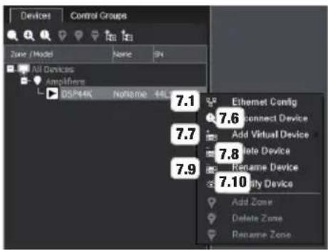
The LD OCS software provides the opportunity to manage multiple LD DSP44K and DSP45K power amps. Click with the right mouse button on the desired amplifier to access the editing menu for power amps.
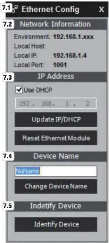
7.1 Ethernet Config - In the Ethernet Config editing window, you can view network information, change the IP address of the power amp, enable DHCP if supported by the network, reset the power amp Ethernet module, assign a name to the power amp, and, with multiple connected power amps, identify a specific one (not possible with USB connection).
7.2 Network Information - Shows network information.
7.3 IP Address - To manually change the IP address, disable DHCP (check the box), enter the address, and click Update IP/DHCP. To reset the Ethernet module of the power amp, click on Reset Ethernet Module.
7.4 Device Name - Enter a name into the input field (8 characters maximum) and click on Change Device Name.
75 Identify Device - To identify a power amp, click on Identify Device; this will display the power amp name and IP address on the device display for a short time.
7.6 Reconnect Device - To recreate an interrupted connection (e.g. after a power outage), click on Reconnect Device.
75 Add Virtual Device - To check or recreate an amp preset offline, you can add a virtual power amp under "Amplifiers". To do so, click on Add Virtual Device and select DSP44K from the LD series. This virtual power amp will be shown as "offline" under series number.
7.8 Delete Device - To delete a power amp from the Amplifiers list, click on Delete Device.
7.9 Rename Device - Click on Rename Device, to rename the power amp, enter a name into the entry field that opens, and click OK.
7.10 Identify Device - To identify a power amp, click on Identify Device; this will display the power amp name and IP address on the device display for a short time (not possible for USB connection).
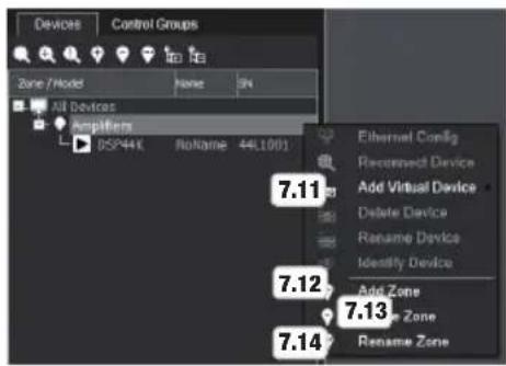
Click with the right mouse button on Amplifiers to access the editing menu.
7.11 Add Virtual Device - To check or recreate an amp preset offline, you can add a virtual power amp under "Amplifiers". To do so, click on Add Virtual Device and select DSP44K from the LD series. This virtual power amp will be shown as "offline" under series number.
7.12 Add new Zone - Adds new zone.
7.13 Delete selected Zone - Deletes selected zone.
7.14 Rename selected Zone - Renames selected zone.
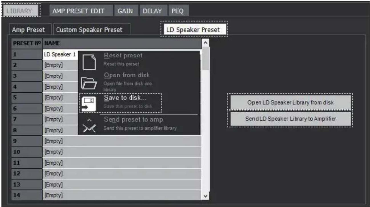
8. LD SPEAKER PRESET LIBRARY
Download the desired LD Systems speaker library from the product page (LDDSP44K / LDDSP45K) at www.LD-SYSTEMS.COM, save it to your PC in a folder of your choice, and unzip it as needed. Start the OCS software and establish a connection with the power amp (USB / Ethernet). Now click on LIBRARY in the overview window, then on LD Speaker Preset and open the previously downloaded LD Systems speaker library by clicking on "Open LD Speaker Library from disk", select the file on your PC, and click Open. The speaker presets will now be displayed with names in the list of speaker presets. Now send the LD speaker library to the power amp by clicking on "Send LD Speaker Library to Amplifier". The presets are now available for use and can be loaded via the selection window for channels CH A to CH D (see 6.28). Click with the right mouse button on the desired preset to individually save the preset as a file on your PC (Save to disk).
9. CREATING AND ADMINISTERING CUSTOM SPEAKER PRESETS
With the OCS software, you have the option to create and manage individual speaker presets (custom speaker presets) for the LD Systems DSP power amps DSP44K and DSP45K. Sign into the OCS software as administrator by clicking on the Mode button in the menu bar, enter the password "admin", and confirm with OK. If a custom speaker library was saved with a personal password, this password must be entered into the corresponding field when signing in. To create new custom speaker presets, click on New Library and the password will reset to "admin".
The editing field SPEAKER PRESET (6.28) will display the EDIT button after signing in. Click on EDIT to open the editing field for custom speaker presets and display the editing options. Configure the OUTPUT ROUTING (single, 2-way, bridge) first when creating a speaker preset.
To protect the custom speaker library with a unique password, click on LIBRARY in the overview window then, under Custom Speaker Preset, click on Change Library Password, enter a custom password, and confirm it in the subsequent window.
Custom libraries that are then to be saved to the computer can only be edited using this personal password because the password is saved with the library. When creating a new library (New Library), the password for it will be reset to the standard password "admin".
Single - Each channel can be configured individually via CHANNEL EDIT and SPEAKER PRESET EDIT and can be managed from a signal source of your choice (SOURCE).
2-way - The channels CH A and CH B or CH C and CH D are configured as a 2-way system, the channels CH A to CH D can be configured individually. In a 2-way system, the signals are controlled via the same signal source. In the CHANNEL EDIT window, only channel CH 1 or CH 3 can be edited.
Bridge - The power amps of channels CH A and CH B or CH C and CH D are each connected to a more powerful power amplifier. Input channel CH 1 and output channel CH A or CH 3 and CH C are available for editing. The signal is controlled via CH 1 or CH 3. Please note the pin allocation of the speaker output socket (printed on the power amp).
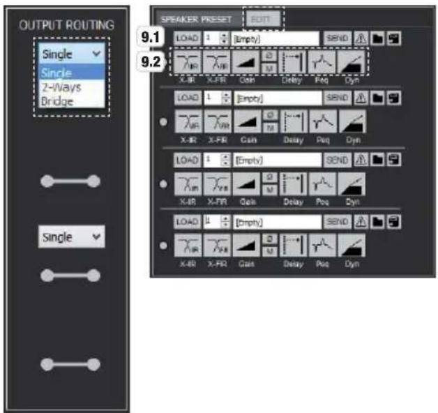
9.1 SPEAKER PRESET
LOAD - Select an amp preset from the speaker preset library using the arrow icons and load it by clicking on LOAD (preset name in the window to the right next to the arrow icons).
SEND - Send a speaker preset to the power amp's storage device and load it.
- Resets the settings of the speaker preset.
- Loads a speaker preset stored on the PC.
- Saves a speaker preset to the PC.
9.2 SPEAKER PRESET EDIT
X-IIR - Button to open the editing window of the X-IIR filter (Infinite Impulse Response).
X-FIR - Button to open the editing window of the X-FIR filter (Finite Impulse Response).
Gain - Button to open the editing window for the signal gain.
- Click this button to invert the polarity of the signal (orange button for inverted polarity).
- Click this button to mute the signal (red button for muted signal).
Delay - Click this button to open the editing window for the signal delay.
The time delay is displayed in meters (m), feet (feet), and milliseconds (ms).
Peq - Click this button to open the editing window for the 16-band parametric equalizer.
Dyn - Click this button to open the editing window for dynamic processing. (Compressor / Limiter).
X-IIR FILTER (INFINITE IMPULSE RESPONSE)
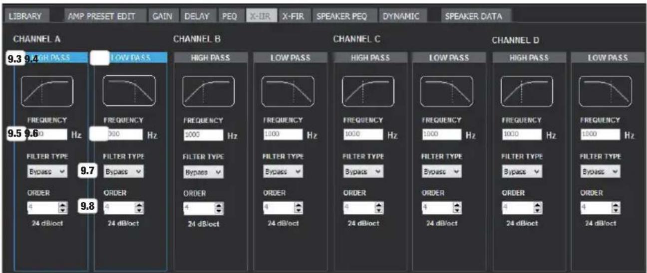
9.3 HIGH PASS - High pass filter.
9.4 LOW PASS - Low pass filter.
9.5 HIGH PASS FREQUENCY - Lower crossover frequency. Entry field for input via keyboard.
9.6 HIGH PASS FREQUENCY - Upper crossover frequency. Entry field for input via keyboard.
9.7 FILTER TYPE - Collapsible menu to select the filter type (Butterworth, Linkwitz-Riley, Bessel) and disable the filter (bypass).
9.8 ORDER - Select the edge steepness of the filter via the arrow icons (1st - 8th order / 6 dB/oct - 48 dB/occt).
X-FIR FILTER (FINITE IMPULSE RESPONSE)
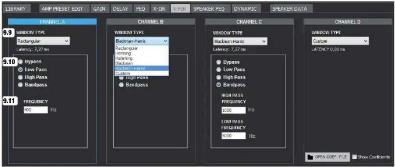
9.9 WINDOW TYPE - Collapsible menu to select the window type (custom = import a coefficient list)
9.10 FILTER - Selection window for bypass and filter types low pass, high pass or bandpass.
9.11 FREQUENCY - Lower or upper crossover frequency (lower and upper crossover frequency for bandpass). Entry field(s) for input via keyboard.
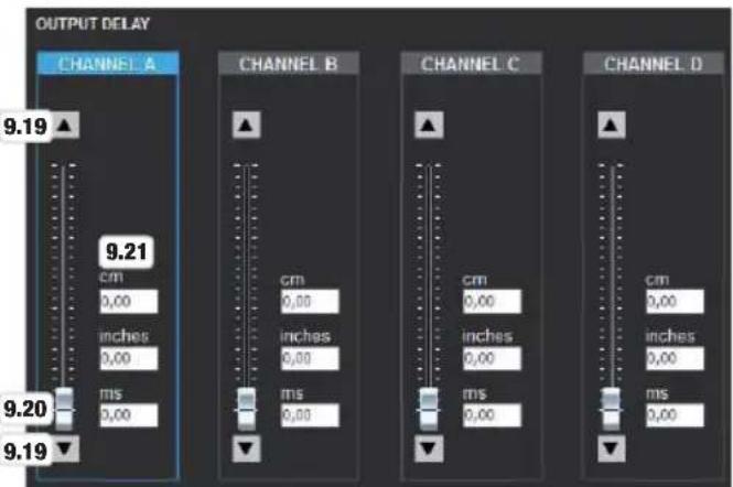
OUTPUT GAIN OUTPUT DELAY
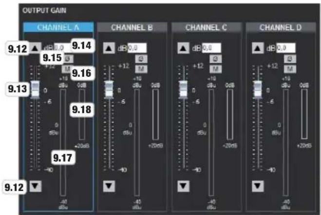
9.12 - Click on the arrow icon (up arrow) to increase or decrease (down arrow) the gain by 0.1 dB.
9.13 Virtual Fader - Click and hold the Virtual Fader button and move it upwards to increase the gain and downwards to decrease it.
9.14 dB Display / Input Field - Displays the gain in dB and allows direct input via keyboard.
9.15 Polarity - Click this button to invert the polarity of the signal and then set it back to normal polarity (orange button for inverted polarity).
9.16 Mute - Click this button to mute the signal and then unmute it (red button for muted signal).
9.17 Signal Level Display
9.18 Display field for gain reduction (limiter)
9.19 - Click on the arrow icon to increase or reduce the signal delay of the corresponding channel.
9.20 Virtual Fader - Click and hold the Virtual Fader button and move it upwards to increase the signal delay and downwards to decrease it.
9.21 Display / Input Fields - Displays the signal delay in centimeters (cm), inches (inches), and milliseconds (ms), and allows direct input via keyboard.
PARAMETRIC SPEAKER EQUALIZER
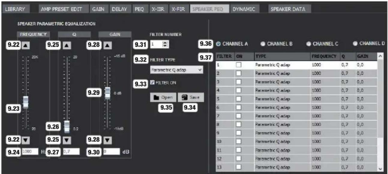
FREQUENCY
9.22 Click on the arrow icon to increase or decrease the chosen EQ band in 1 Hz intervals.
9.23 Virtual Fader - Click and hold the Virtual Fader button and move it upwards to increase the frequency and downwards to decrease it.
9.24 Display / Input Field - Displays the frequency in Hertz (Hz) and allows direct input via keyboard.
FILTER QUALITY Q
9.25 Click on the arrow icon to set the quality factor of the chosen EQ band from 0.2 to 20.
9.26 Virtual Fader - Click and hold the Virtual Fader button and move it upwards to increase the quality factor and downwards to decrease it.
9.27 Display / Input Field - Displays the quality factor and allows direct input via keyboard.
GAIN
9.28 - Click on the arrow icon to increase or decrease the gain of the chosen EQ band in 0.1 dB intervals.
9.20 Virtual Fader - Click and hold the Virtual Fader button and move it upwards to increase the gain and downwards to decrease it.
9.30 dB Display / Input Field - Displays the gain in dB and allows direct input via keyboard.
9.31 FILTER NUMBER - Displays the filter number and allows selection of filters 1 to 16 using the arrow icons (selected band is highlighted in white).
9.32 FILTER TYPE - Collapsible menu to select the filter type in the EQ bands 1 to 16.
9.33 FILTER ON - Check the box on the control panel to activate the chosen filter, deactivate the filter by unchecking the box (bypass).
9.34 Save - Use this button to save the filter settings of each 16 EQ band as an EQ preset file to your PC.
9.35 Open - Load a previously saved EQ preset from the PC to the selected channel A to D.
9.36 CHANNEL A to D - Select the desired channel for editing by clicking on the channel button.
9.37 EQ 1 to 16 - Overview window for EQs 1 to 16. Enable or disable the desired EQ bands using the mouse (checking ON = EQ band enabled, unchecking = EQ band disabled).
SPEAKER DYNAMIC CONTROL
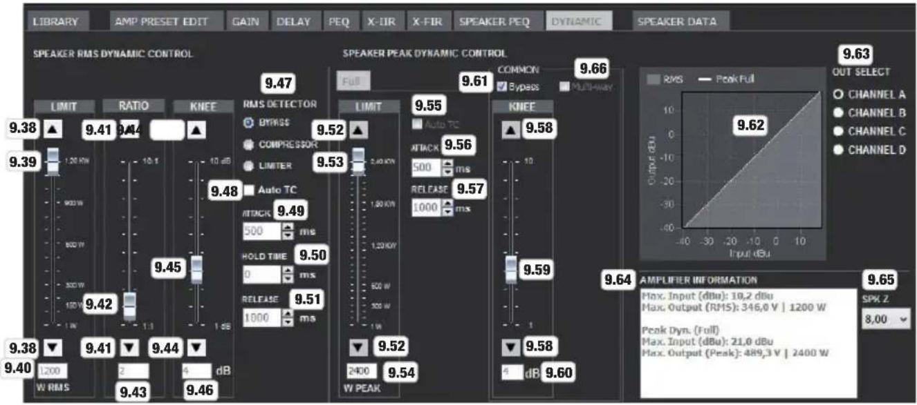
SPEAKER RMS DYNAMIC CONTROL
9.38 LIMIT -Click on the arrow icon to adjust the limiter to the RMS capacity of the speaker.
9.39 Virtual Fader - Click and hold the Virtual Fader button and move it upwards or downwards to adjust the limiter to the RMS capacity of the speaker.
9.40 Display / Input Field - Displays the limitation in watts RMS and allows direct input via keyboard.
9.41 RATIO Click on the arrow icon to configure the control ratio when using as a compressor.
9.42 Virtual Fader - Click and hold the Virtual Fader button and move it upwards or downwards to set the control ratio when using as a compressor.
9.43 Display / Input Field - Displays the control ratio and allows direct input via keyboard.
9.44 KNEE - Click on the arrow icon to adjust the characteristic curve to the height of the threshold value (in this case, W RMS) (low value = hard transition between raw and processed signal, high value = soft transition between raw and processed signal).
9.45 Virtual Fader - Click and hold the Virtual Fader button and move it upwards or downwards to adjust the characteristic curve to the height of the threshold value (in this case, W RMS).
9.46 Display / Input Field - Displays the value and allows direct input via keyboard.
9.47 RMS DETECTOR
BYPASS - RMS DYNAMIC CONTROL disabled (click button).
COMPRESSOR - Use as compressor (click button).
LIMITER - Use as limiter (click button).
9.48 Auto TC - Check box to automatically set Attack, Hold Time, and Release.
9.49 ATTACK - Allows manual configuration of the response time via the arrow icons and direct input via keyboard (unchecked box for Auto TC).
9.50 HOLD TIME - Allows manual configuration of the hold time via the arrow icons and direct input via keyboard (unchecked box for Auto TC).
9.51 RELEASE - Allows manual configuration of the release time via the arrow icons and direct input via keyboard (unchecked box for Auto TC).
SPEAKER PEAK DYNAMIC CONTROL
9.52 LIMIT Click on the arrow icon to adjust the limiter to the peak capacity of the speaker.
9.53 Virtual Fader - Click and hold the Virtual Fader button and move it upwards or downwards to adjust the limiter to the peak capacity of the speaker.
9.54 Display / Input Field - Displays the limitation in watts PEAK and allows direct input via keyboard.
9.55 Auto TC - Check box to automatically set Attack and Release.
9.56 ATTACK - Allows manual configuration of the response time via the arrow icons and direct input via keyboard (unchecked for Auto TC).
9.57 RELEASE - Allows manual configuration of the release time via the arrow icons and direct input via keyboard (unchecked box for Auto TC).
9.58 KNEE - Click on the arrow icon to adjust the characteristic curve to the height of the threshold value (in this case, W PEAK) (low value = hard transition between raw and processed signal, high value = soft transition between raw and processed signal).
9.59 Virtual Fader - Click and hold the Virtual Fader button and move it upwards or downwards to adjust the characteristic curve to the height of the threshold value (in this case, W RMS).
9.60 Display / Input Field - Displays the value and allows direct input via keyboard.
9.61 Bypass - Check box to deactivate PEAK DYNAMIC CONTROL.
9.62 Graphic depiction of both dynamic control units (gray area = RMS DYNAMIC CONTROL, white line = PEAK DYNAMIC).
9.63 OUT SELECT - Select the desired channel for editing by clicking on the channel button.
9.64 AMPLIFIER INFORMATION - Input and output specifications of the amplifier.
9.65 SPK Z - Collapsible menu to configure the speaker impedance.
9.66 Multi-way - Check box to activate the 2-band limiter.
MULTI-WAY LIMITER
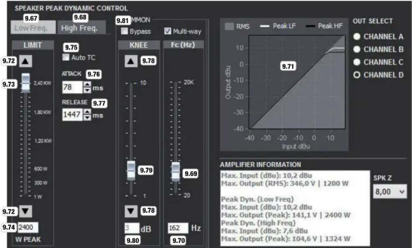
9.67 Low Freq. - Limiter for the low band. Click button to edit (highlighted in light gray).
9.68 High Freq. - Limiter for the high band. Click button to edit (highlighted in light gray).
9.69 Virtual Fader - Click and hold the Virtual Fader button and move it upwards or downwards to set the crossover frequency between the low and high band.
9.70 Display / Input Field - Displays the crossover frequency and allows direct input via keyboard.
9.71 Graphic depiction of both dynamic control units (gray area = RMS DYNAMIC CONTROL, white line = PEAK DYNAMIC CONTROL low band, black line = PEAK DYNAMIC CONTROL high band).
9.72 LIMIT Click on the arrow icon to adjust the limiter to the peak capacity of the speaker.
9.73 Virtual Fader - Click and hold the Virtual Fader button and move it upwards or downwards to adjust the limiter to the peak capacity of the speaker.
9.74 Display / Input Field - Displays the limitation in watts PEAK and allows direct input via keyboard.
9.75 Auto TC - Check box to automatically set Attack and Release.
9.76ATTACK- Allows manual configuration of the response time via the arrow icons and direct input via keyboard (unchecked box for Auto TC).
9.77 RELEE - Alows manual configuration of the release time via the arrow icons and direct input via keyboard (uncheck box for Auto TC).
9.78 KNEE - Click on the arrow icon to adjust the characteristic curve to the height of the threshold value (in this case, W PEAK) (low value = hard transition between raw and processed signal, high value = soft transition between raw and processed signal).
9.79 Virtual Fader - Click and hold the Virtual Fader button and move it upwards or downwards to adjust the characteristic curve to the height of the threshold value (in this case, W PEAK).
9.30 Display / Input Field - Displays the value and allows direct input via keyboard.
9.81 Bypass - Check box to deactivate PEAK DYNAMIC CONTROL.
FREQUENCY RESPONSE (SIGNED IN AS ADMINISTRATOR)
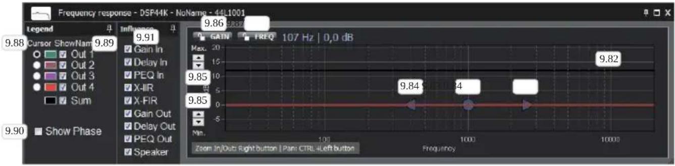
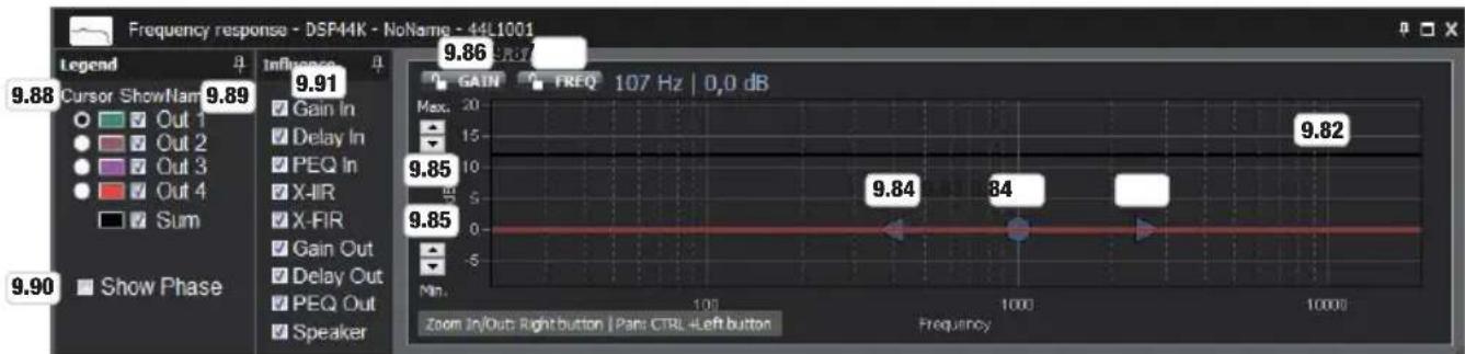
9.82 Frequency Response - Graphic depiction of the frequency response. (Zooming in horizontally: Mark the desired area by dragging the mouse cursor to the right. Zooming out horizontally: Mark the area by dragging the mouse cursor to the left. Push vertically with Ctrl and left mouse button)
9.83 GAIN and FREQUENCY grip point - Click and hold this grip point to change the frequency and gain of the chosen frequency band by moving it horizontally and vertically.
9.84 Grip point FILTER QUALITY Q - Click and hold a grip point to change the filter quality of the chosen frequency band by dragging horizontally as desired.
9.85 Max. / Min. - Zoom in vertically using the arrow icons.
9.86 Disable GAIN - Click on this button to suspend editing of the gain on the graphical window (red button) or to again allow editing (gray button).
9.87 Disable FREQ - Click on this button to suspend editing of the frequency on the graphical window (red button) or to again allow editing (gray button).
9.88 Cursor - Select which channel the cursor will follow on the graphical window (frequency and gain displays).
9.89 Show Name - Select which channel will be shown on the graphical window. Click the color buttons to set the line color individually.
9.90 Show Phase - Check the box to display the phase response on the graphical window.
9.91 Influence - Check a box in the input field of processing options to be shown in the frequency curve.
SPEAKER DATA
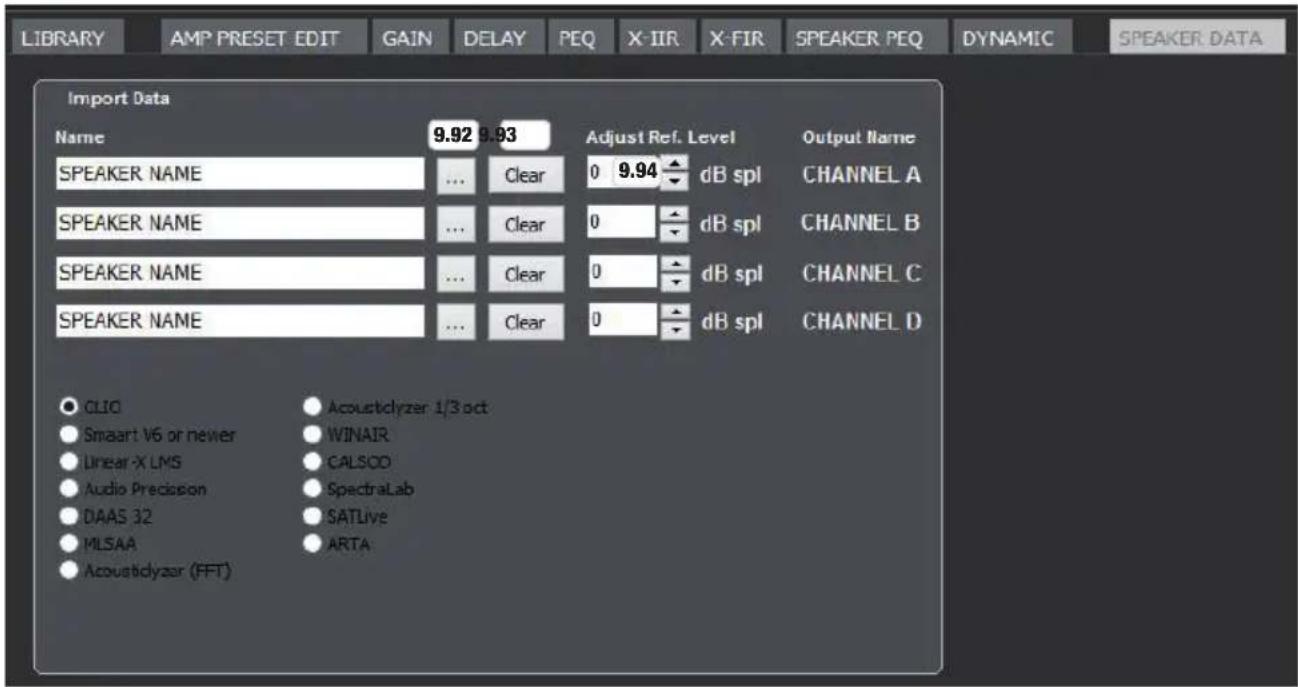
Editing window to import speaker measurement data from various measurement systems.
9.92 Importing the measurement data.
9.93 Clear - Deletes the measurement data.
9.94 Adjust Ref. Level - Level adjustment via the arrow icons.
ADMINISTERING CUSTOM SPEAKER PRESETS
In the overview window, click on LIBRARY and then on Custom Speaker Preset. You can now import the custom speaker presets previously saved to the PC into the preset list (Open from disk), construct a custom library, and save all of this to a file on your PC and send it to the power amp.
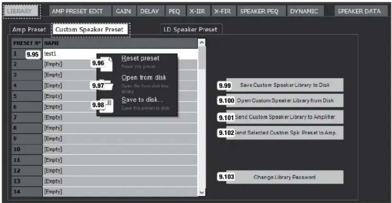
9.95 List of custom speaker presets (1 - 80).
9.96 Reset Preset - Removes a preset from the list. Click on the desired preset with the right mouse button, then click on Reset Preset and confirm with Yes.
9.97 Open from Disk - Loads a preset from the PC to the list. Click on a free preset (empty) with the right mouse button, then click on Open from disk, and select the desired preset from your PC's hard drive and click on Open.
9.98 Save to disk - Save the preset to your PC. Click on the desired preset with the right mouse button, then click on Save to disk, and select a location to save it, name the preset as desired, then click on Save.
9.99 Save Custom Speaker Library to Disk - Saves all presets in the list to a file on your PC. Click on Save Custom Speaker Library to Disk, and select a location to save it, name the library as desired, then click on Save.
9.100 Open Custom Speaker Library from Disk - Import a custom speaker preset library from the PC into the preset list. Click on Open Custom Speaker Library from Disk, and select the desired file from your PC hard drive and click on Open.
9.101 Send Custom Speaker Library to Amplifier - Sends and saves the currently loaded custom speaker preset library to the power amplifier. Click on Send Custom Speaker Library to Amplifier. The process will take several seconds.
9.102 Send Selected Custom Spk. Preset to Amp - Sends a preset from the list to the preset library of the power amp. Click to select the desired preset and then click on Send Selected Custom Spk. Preset to Amp.
9.103 Change Library Password - To protect the custom speaker library with a unique password, click on LIBRARY in the overview window then, under Custom Speaker Preset click on Change Library Password, enter a custom password, and confirm it in the subsequent window. Custom libraries that are then to be saved to the computer can only be edited using this personal password because the password is saved with the library. When creating a new library (New Library), the password for it will be reset to the standard password "admin".
10. CREATING AND ADMINISTERING AMP PRESETS
An amp preset consists of the choice of speaker presets from the custom speaker preset and LD speaker preset libraries (Library) and the settings options in the CHANNEL EDIT area (6.26). Select the desired speaker presets for channels CH A to CH D (6.28) and adjust the gain, polarity, muting, delay, and equalizer depending on the intended purpose and in real time when needed. An amp preset created in this way can be both loaded directly to the power amp (see 6.23 AMP PRESET - SEND) as well as saved as a file to your PC. In both cases, select an empty preset on the AMP PRESET control panel (6.23) using the arrow icons and enter a name for the preset into the display or input window. To load the amp preset to the power amp, now click on SEND (Send Amp Preset to Amplifier Library) to save it as a file to your PC, click on the diskette symbol (Save an Amp Preset File to disk), select a storage location on your PC, and save it.
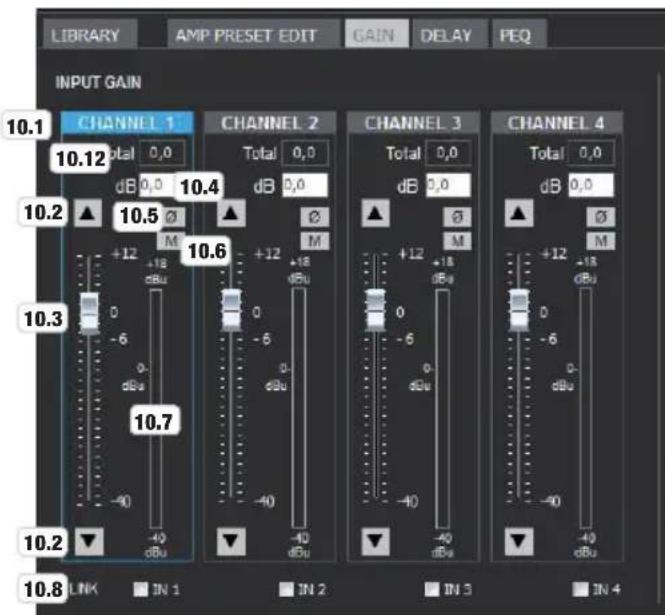
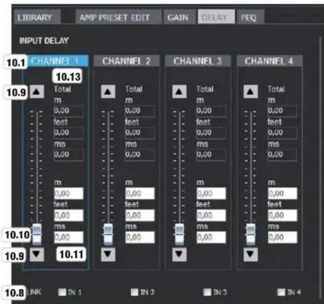
INPUT GAIN INPUT DELAY
10.1 CHANNEL 1 to 4 - As soon as you click on the editing field of the desired channel, the border color will change to blue.
10.2 - Click on the arrow icon (up arrow) to increase or decrease (down arrow) the gain by 0.1 dB.
10.3 Virtual Fader - Click and hold the Virtual Fader button and move it upwards to increase the gain or downwards to decrease it.
10.4 dB Display / Input Field - Displays the amplification in dB and allows direct input via keyboard.
10.5 Polarity - Click this button to invert the polarity of the signal and then set it back to normal polarity (orange button for inverted polarity)
10.6 Mute - Click this button to mute the signal and then unmute it (red button for muted signal).
10.7 Signal Level Display
10.8 LINK - Before editing, you can link the channels whose settings are to be the same (check the box).
The settings must therefore only be applied to one channel and will be automatically applied to linked channels.
10.9 - Click on the arrow icon to increase or reduce the signal delay of the corresponding channel.
10.10 Virtual Fader - Click and hold the Virtual Fader button and move it upwards to increase the signal delay or downwards to decrease it.
10.11 Display / Input Fields - Displays the signal delay in meters (m), feet (feet), and milliseconds (ms), and allows direct input via keyboard.
10.12 Total Gain - Displays the sum of the INPUT CHANNEL GAIN and GROUP GAIN in dB.
10.13 Total Delay - Displays the sum of INPUT CHANNEL DELAY and GROUP DELAY in meters (m), feet (feet), and milliseconds (ms).
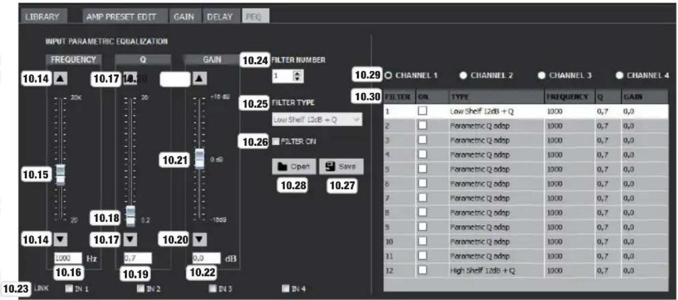
PARAMETRIC INPUT EQUALIZER
FREQUENCY
10.14 - Click on the arrow icon to increase or decrease the chosen EQ bands in 1 Hz intervals.
10.15 Virtual Fader - Click and hold the Virtual Fader button and move it upwards to increase the frequency or downwards to decrease it.
10.16 Display / Input Field - Displays the frequency in Hertz (Hz) and allows direct input via keyboard.
FILTER QUALITY Q
10.17 Click on the arrow icon to set the quality factor of the chosen EQ band from 0.2 to 20.
10.18 Virtual Fader - Click and hold the Virtual Fader button and move it upwards or downwards to set the quality factor as desired.
10.19 Display / Input Field - Displays the quality factor and allows direct input via keyboard.
GAIN
10.20 - Click on the arrow icon to increase or decrease the gain of the chosen EQ band in 0.1 dB intervals.
10.21 Virtual Fader - Click and hold the Virtual Fader button and move it upwards or downwards to set the gain as desired.
10.22 dB Display / Input Field - Displays the gain in dB and allows direct input via keyboard.
10.23 LINK - Before editing, you can link the channels whose settings are to be the same (check the box). The settings must therefore only be applied to one channel and will be automatically applied to linked channels.
10.24 FILTER NUMBER - Displays the filter number and allows selection of filters 1 to 12 using the arrow icons (selected band is lighted in white).
10.25 FILTER TYPE - The filter type of the filter in channels 1 to 4 cannot be selected and is therefore grayed out (Filter 1 = low shelf, Filter 2 - 11 = parametric, Filter 12 = high shelf).
10.26 FILTER ON - Check the box on the control panel to activate the chosen filter, deactivate the filter by unchecking the box (bypass).
10.27 Save - Use this button to save the filter settings of each 12 EQ band as an EQ preset file to your PC.
10.28 Open - Load a previously saved EQ preset from the PC to the selected channel 1 to 4.
10.29 CHANNEL 1 to 4 - Select the desired channel for editing by clicking on the channel button.
10.30 EQ 1 to 12 - Overview window for EQs 1 to 12. Enable or disable the desired EQ bands using the mouse (checking ON = EQ band enabled, unchecking = EQ band disabled).
FREQUENCY RESPONSE (NOT SIGNED IN AS ADMINISTRATOR)
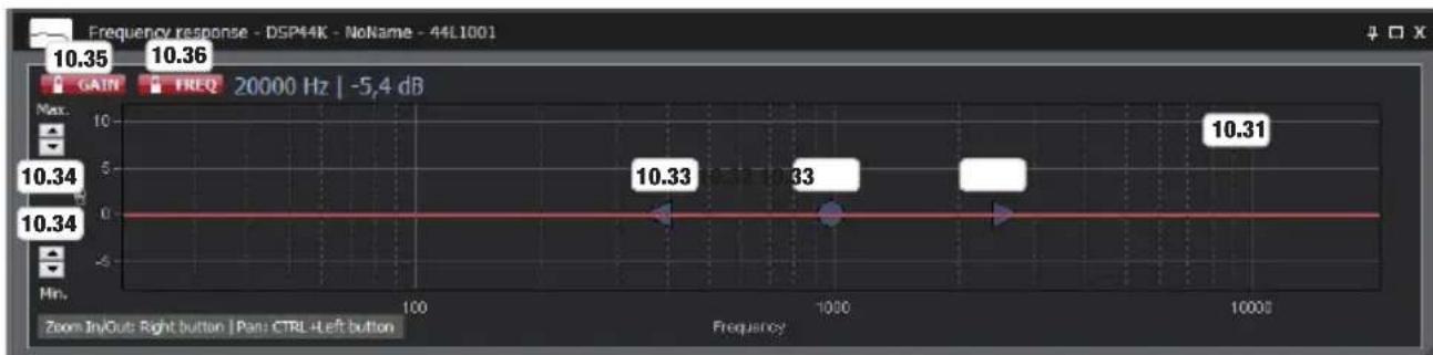
10.31 Frequency Response - Graphic depiction of the frequency response. (Zooming in horizontally: Mark the desired area by dragging the mouse cursor to the right. Zooming out horizontally: Mark the area by dragging the mouse cursor to the left. Push vertically with Ctrl and left mouse button).
Note: In order to determine yourself which channel the cursor will follow when moving over the graphic (9.88), please log in to the OCS software as administrator (6.9).
10.32 GAIN and FREQUENCY grip point - Click and hold this grip point to change the frequency and gain of the chosen frequency band by moving it horizontally and vertically.
10.33 Grip point FILTER QUALITY Q - Click and hold a grip point to change the filter quality of the chosen frequency band by dragging horizontally as desired.
10.34 Max./Min.-Zoom in vertically using the arrow icons.
10.35 Disable GAIN - Click on this button to suspend editing of the gain on the graphical window (red button) or to again allow editing (gray button).
10.36 Disable FREQ - Click on this button to suspend editing of the frequency on the graphical window (red button) or to again allow editing (gray button).
ADMINISTERING AMP PRESETS
In the overview window, click on LIBRARY and then on Amp Preset. You can now import the amp presets (see 6.23) previously saved to the PC into the presets list (Open from disk), construct a custom library, and save all of this to a file on your PC and send it to the power amp.
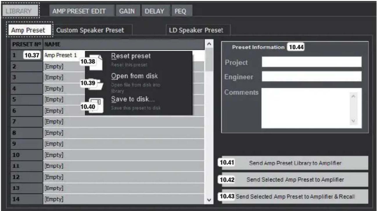
10.37 List of amp presets (1 - 80).
10.38 Reset Preset - Removes a preset from the list. Click on the desired preset with the right mouse button, then click on Reset Preset, and confirm with Yes.
10.39 Open from Disk - Loads a preset from the PC to the list. Click on a free preset (empty) with the right mouse button, then click on Open from Disk, and select the desired preset from your PC's hard drive and click on Open.
10.40 Save to Disk - Save the preset to your PC. Click on the desired preset with the right mouse button, then click on Save to disk, select a location to save it, name the preset as desired, then click on Save.
10.41 Send Amp Preset Library to Amplifier - Sends and saves the currently loaded amp preset library to the power amplifier. Click on Send Amp Preset Library to Amplifier. The process will take several seconds.
10.42 Send Selected Amp Preset to Amplifier - Sends a preset from the list to the preset library of the power amp. Click on the desired preset with the right mouse button, then click on Send Selected Amp Preset to Amplifier
10.43 Send Selected Amp Preset to Amplifier & Recall - Sends and loads a preset from the list to the preset library of the power amp. Click on the desired preset with the right mouse button, then click on Send Selected Amp Preset to Amplifier & Recall.
10.44 Preset Information - Enter a project name, the name of the preset author, and comments, as needed.
To manage the amp preset library, see items 6.2 to 6.7 in the overview window.
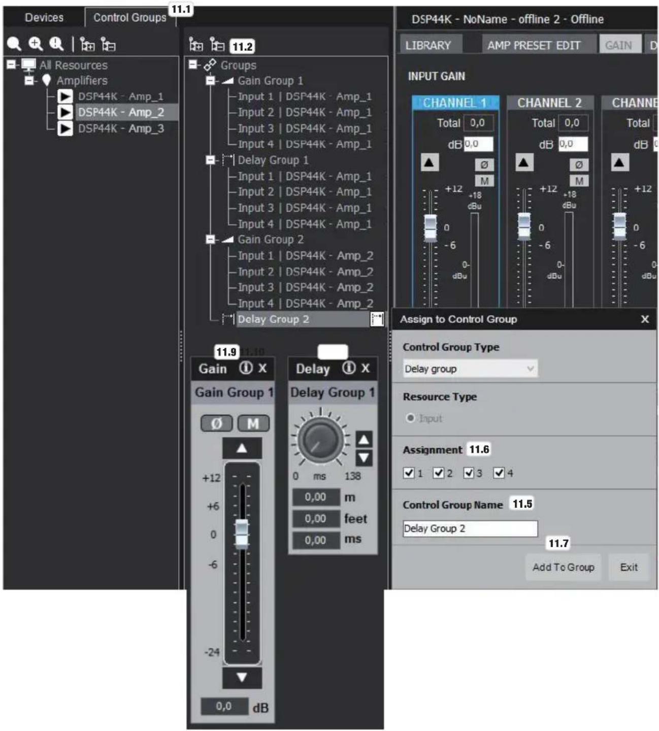
11. CONTROL GROUPS
The control groups make it possible to freely group and simultaneously manage the input gain and input delay of the desired channels for the power amps connected to the computer via Ethernet. The control of the input gain and the input delay in these groups is relative to the settings in the input channels of the corresponding power amplifiers, meaning the gain and delay of the control group and input channel are added together and the result is displayed as a total value (Total).
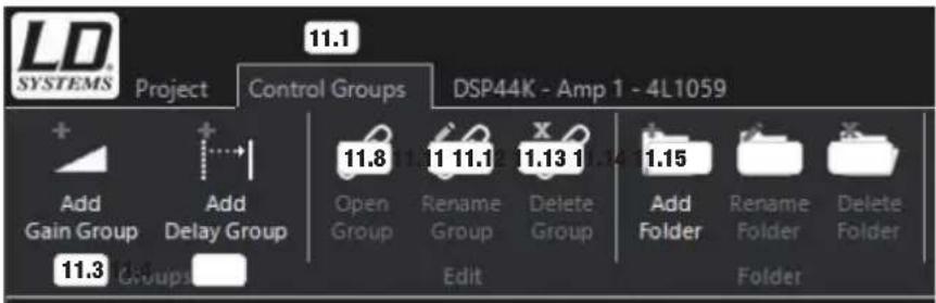
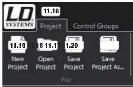
The corresponding power amps must be recognized by the system in order to create gain and delay groups as needed. Now click on the Control Groups button (no. 11.1). This will open the group window. Click once on Groups (no. 11.2) and then add the gain groups and delay groups as desired by clicking the Add Gain Group (no. 11.3) and Add Delay Group buttons (11.4) on the menu bar. Name the groups as desired and click on OK. Add a power amp for a gain group and/or delay group via drag and drop. Now the Assign to Control Group window will open, where you can name the gain or delay group (Control Group Name, no. 11.5), select to which of the 4 power amp channels the group is to be assigned (assignment, no. 11.6), and click on Add To Group (no. 11.7). Mark the group you would like to edit (click 1x), and click on Open Group (no. 11.8) on the menu bar. You can apply your desired settings to the windows that will open (no. 11.9 and 11.10). Groups can be renamed or deleted by clicking on the desired group and then clicking the corresponding button (Rename Group no. 11.11 and Delete Group no. 11.12). Groups can be collected in folders by clicking on Groups (no. 11.2), then clicking on Add Folder (no. 11.13) and dragging and dropping the desired control groups to the folder (Rename and delete folder via Rename Folder no. 11.14 and Delete Folder no. 11.15). To save the control groups and device settings to a file, click on Project (no. 11.16) and then Save Project (no. 11.17). Name the file as desired and save it to your computer. The speaker and amp presets used in the project will not be saved with the project file; they must therefore be loaded to the DSP44 or DSP45 used. Open a project by clicking on Open Project (no. 11.18), create a new project by clicking on New Project (no. 11.19), and save the current project under a new name by clicking on Save Project As (no. 11.20).
12. FIRMWARE UPDATE
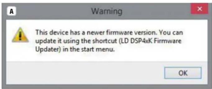
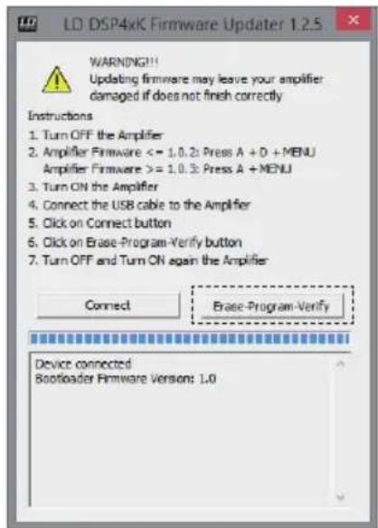
A firmware update keeps the device software up-to-date and improves software performance. When you install the latest LD OCS software onto your PC and connect an LD DSP44K or DSP45K power amp with your computer, the OCS software will automatically indicate when newer device firmware is available than that currently installed for the power amp (Fig. A). Be very diligent with firmware updates, complete all steps exactly as instructed, do not interrupt the update process, and ensure that the USB connection between the PC and the power amplifier is not interrupted. If the firmware update is not allowed to finish properly, the power amp may become damaged and unusable.
The firmware updater is automatically installed when installing the latest LD OCS software. You will find the firmware updater in the Windows Start menu.
LD Systems

LD DSP4xK Firmware Updater
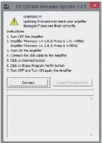
Start the firmware updater and follow the steps shown carefully!
- Switch off the power amp.
- Hold the A and D and MENU buttons of the power amp at the same time (up to firmware 1.0.2., firmware 1.0.3+: A button and MENU)
- Switch on the power amp and hold the three buttons until "BOOTLoader MODE" is shown on the device display. Do not press any control buttons until the update has completed.
BOOTLOADER MODE
Don't touch
any button
- Connect the power amp and the PC using a suitable USB cable (USB 2.0, USB-A to USB-B).
- Click on the Connect button in the updater window. "Device connected" will now be shown in the information window.
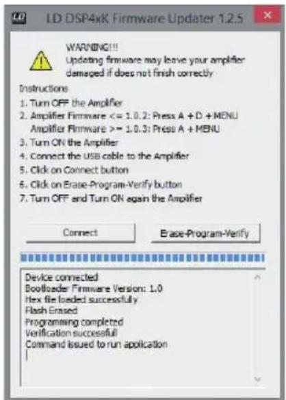
- Now click on the Erase-Program-Verify button. The process will take a moment.
- As soon as the update process is complete, this will be shown on the information window ("Programming completed" and "Verification successful"). Now switch off the power amp and switch it back on after a short time. The OCS software can now be started as usual.
HAFTUNGSAUSSCHLUSS
92 SPEAKER PRESET EDIT
FREQUENCY RESPONSE (ALS ADMINISTRATOR ANGEMELDET)
Don't touch any button
9.2 SPEAKER PRESET EDIT
Don't touch any button
9.2 SPEAKER PRESET EDIT
X-IIR - Przycisk otwierajcy okno edycij filtra X-IIR (Infinite Impulse Response).
X-FIR - Przycisk owierajacy okno edyci filtra X-FIR (Finite Impulse Response).


- INTRODUCTION
- SOFTWARE INSTALLATION
- CREATING CONNECTION VIA USB
- CREATING CONNECTION VIA ETHERNET
- PREFERENCES
- OVERVIEW WINDOW
- MANAGING POWER AMPLIFIERS
- LD SPEAKER PRESET LIBRARY
- CREATING AND ADMINISTERING CUSTOM SPEAKER PRESETS
- SPEAKER PRESET
- SPEAKER PRESET EDIT
- X-IIR FILTER (INFINITE IMPULSE RESPONSE)
- X-FIR FILTER (FINITE IMPULSE RESPONSE)
- OUTPUT GAIN OUTPUT DELAY
- PARAMETRIC SPEAKER EQUALIZER
- FREQUENCY
- FILTER QUALITY Q
- GAIN
- SPEAKER DYNAMIC CONTROL
- SPEAKER RMS DYNAMIC CONTROL
- SPEAKER PEAK DYNAMIC CONTROL
- MULTI-WAY LIMITER
- FREQUENCY RESPONSE (SIGNED IN AS ADMINISTRATOR)
- SPEAKER DATA
- ADMINISTERING CUSTOM SPEAKER PRESETS
- CREATING AND ADMINISTERING AMP PRESETS
- FREQUENCY RESPONSE (NOT SIGNED IN AS ADMINISTRATOR)
- ADMINISTERING AMP PRESETS
- CONTROL GROUPS
- FIRMWARE UPDATE
- LD Systems
- Start the firmware updater and follow the steps shown carefully!
- BOOTLOADER MODE
- HAFTUNGSAUSSCHLUSS
- SPEAKER PRESET EDIT
Brand : LD Systems
Model : DSP 44 K
Category : Receiver