
MAUI 28 G2 - Loudspeaker LD Systems - Free user manual and instructions
Find the device manual for free MAUI 28 G2 LD Systems in PDF.
| Product Type | Active column PA system |
| Model | LD Systems MAUI 28 G2 |
| Available Colors | Black (MAUI 28 G2) or White (MAUI 28 G2W) |
| Max SPL (peak) | 126 dB SPL |
| Frequency Response | 45 Hz - 20 kHz |
| Dispersion Angle (H x V) | 120° x 20° |
| Total Height | 2059 mm |
| Total Weight | 30.9 kg |
| Subwoofer Configuration | 2 x 8" (203 mm) speakers, ferrite woofer, 50.8 mm coil |
| Mid/High Column Configuration | 16 x 3" (76.2 mm) mids + 2 x 1" (25.4 mm) neodymium tweeters |
| Amplifier Power (peak) | 1000 W (Class D, 3 channels) |
| Built-in Bluetooth | Yes, wireless audio streaming |
| Built-in Mixer | 4 channels (MIC, HI-Z, LINE, MP3/BT) |
| Digital Signal Processing (DSP) | DynX® (multiband limiter, equalizer, compressor, crossover) |
| Inputs | 1 x MIC (Combo XLR/6.35 mm jack), 2 x LINE (RCA + Combo), 1 x HI-Z (6.35 mm jack), 1 x MP3 (3.5 mm mini-jack) |
| Outputs | 1 x SYSTEM OUT (XLR), 1 x SUB OUT (XLR) |
| Power Supply | 100-120 V / 200-240 V, 50-60 Hz (auto-switching) |
| Subwoofer Material | 15 mm plywood with textured paint |
| Column Material | Aluminum with long-lasting finish |
| Protections | Thermal overload, multiband limiter, short-circuit, DC protection |
| Optional Accessories | Transport bag, protective cover, trolley, stands, wall mounting kits |
| Maintenance and Cleaning | Use a dry cloth for cleaning. Do not use solvents. |
| Safety Instructions | Read the manual carefully, do not open the device, avoid moisture and heat sources, use a grounded outlet. |
Frequently Asked Questions - MAUI 28 G2 LD Systems
User questions about MAUI 28 G2 LD Systems
0 question about this device. Answer the ones you know or ask your own.
Ask a new question about this device
Download the instructions for your Loudspeaker in PDF format for free! Find your manual MAUI 28 G2 - LD Systems and take your electronic device back in hand. On this page are published all the documents necessary for the use of your device. MAUI 28 G2 by LD Systems.
USER MANUAL MAUI 28 G2 LD Systems
MAUI 28 G2
COMPACT COLUMN PA SYSTEM WITH MIXER AND BLUETOOTH®
LDMAUI28G2 / LDMAUI28G2W
CONTENTS / INHALTSVERZEICHNIS / CONTENU / CONTENIDO / TREŚĆ / CONTENUTO /
目录 / 目錄
ENGLISH
PREVENTIVE MEASURES 3-4
INTRODUCTION
CONNECTIONS, CONTROLS AND INDICATORS 6-9
CABLING EXAMPLES 9-10
OPTIONAL ACCESSORIES 11
TECHNICAL SPECIFICATIONS 11
MANUFACTURER INFORMATION 13
DEUTSCH
SICHERHEITSHINWEISE
EINFÜHRUNG
We have designed this product to operate reliably over many years. LD Systems stands for this with its name and many years of experience as a manufacturer of high-quality audio products. Please read this User's Manual carefully, so that you can begin making optimum use of your LD Systems product quickly.
You can find more information about LD-SYSTEMS at our Internet site WWW.LD-SYSTEMS.COM
PREVENTIVE MEASURES
- Please read these instructions carefully.
- Keep all information and instructions in a safe place.
- Follow the instructions.
- Observe all safety warnings. Never remove safety warnings or other information from the equipment.
- Use the equipment only in the intended manner and for the intended purpose.
- Use only sufficiently stable and compatible stands and/or mounts (for fixed installations). Make certain that wall mounts are properly installed and secured. Make certain that the equipment is installed securely and cannot fall down.
- During installation, observ e the applicable safety regulations for your country.
- Never install and operate the equipment near radiators, heat registers, ovens or other sources of heat. Make certain that the equipment is always installed so that is cooled sufficiently and cannot overheat.
- Never place sources of ignition, e.g., burning candles, on the equipment.
- Ventilation slits must not be blocked.
- Keep a minimum distance of 20 cm around and above the device.
- Do not use this equipment in the immediate vicinity of water (does not apply to special outdoor equipment - in this case, observe the special instructions noted below. Do not expose this equipment to flammable materials, fluids or gases. Avoid direct sunlight!
- Make certain that dripping or splashed water cannot enter the equipment. Do not place containers filled with liquids, such as vases or drinking vessels, on the equipment.
- Make certain that objects cannot fall into the device.
- Use this equipment only with the accessories recommended and intended by the manufacturer.
- Do not open or modify this equipment.
- After connecting the equipment, check all cables in order to prevent damage or accidents, e.g., due to tripping hazards.
- During transport, make certain that the equipment cannot fall down and possibly cause property damage and personal injuries.
- If your equipment is no longer functioning properly, if fluids or objects have gotten inside the equipment or if it has been damaged in another way, switch it off immediately and unplug it from the mains outlet (if it is a powered device). This equipment may only be repaired by authorized, qualified personnel.
- Clean the equipment using a dry cloth.
- Comply with all applicable disposal laws in your country. During disposal of packaging, please separate plastic and paper/cardboard.
- Plastic bags must be kept out of reach of children.
- Please note that changes or modifications not expressly approved by the party responsible for compliance could void the user's authority to operate the equipment.
FOR EQUIPMENT THAT CONNECTS TO THE POWER MAINS
- CAUTION: If the power cord of the device is equipped with an earthing contact, then it must be connected to an outlet with a protective ground. Never deactivate the protective ground of a power cord.
- If the equipment has been exposed to strong fluctuations in temperature (for example, after transport), do not switch it on immediately. Moisture and condensation could damage the equipment. Do not switch on the equipment until it has reached room temperature.
- Before connecting the equipment to the power outlet, first verify that the mains voltage and frequency match the values specified on the equipment. If the equipment has a voltage selection switch, connect the equipment to the power outlet only if the equipment values and the mains power values match. If the included power cord or power adapter does not fit in your wall outlet, contact your electrician.
- Do not step on the power cord. Make certain that the power cable does not become kinked, especially at the mains outlet and/or power adapter and the equipment connector.
- When connecting the equipment, make certain that the power cord or power adapter is always freely accessible. Always disconnect the equipment from the power supply if the equipment is not in use or if you want to clean the equipment. Always unplug the power cord and power adapter from the power outlet at the plug or adapter and not by pulling on the cord. Never touch the power cord and power adapter with wet hands.
- Whenever possible, avoid switching the equipment on and off in quick succession because otherwise this can shorten the useful life of the equipment.
- IMPORTANT INFORMATION: Replace fuses only with fuses of the same type and rating. If a fuse blows repeatedly, please contact an authorised service centre.
- To disconnect the equipment from the power mains completely, unplug the power cord or power adapter from the power outlet.
- If your device is equipped with a Volex power connector, the mating Volex equipment connector must be unlocked before it can be removed. However, this also means that the equipment can slide and fall down if the power cable is pulled, which can lead to personal injuries and/or other damage. For this reason, always be careful when laying cables.
- Unplug the power cord and power adapter from the power outlet if there is a risk of a lightning strike or before extended periods of disuse.

CAUTION:
To reduce the risk of electric shock, do not remove cover (or back). There are no user serviceable parts inside. Maintenance and repairs should be exclusively carried out by qualified service personnel.
The warning triangle with lightning symbol indicates dangerous uninsulated voltage inside the unit, which may cause an electrical shock.

The warning triangle with exclamation mark indicates important operating and maintenance instructions.
Warning! This symbol indicates a hot surface. Certain parts of the housing can become hot during operation. After use, wait for a cool-down period of at least 10 minutes before handling or transporting the device.

Warning! This device is designed for use below 2000 metres in altitude.

Warning! This product is not intended for use in tropical climates.
CAUTION! HIGH VOLUMES IN AUDIO PRODUCTS!
This device is meant for professional use. Therefore, commercial use of this equipment is subject to the respectively applicable national accident prevention rules and regulations. As a manufacturer, Adam Hall is obligated to notify you formally about the existence of potential health risks. Hearing damage due to high volume and prolonged exposure: When in use, this product is capable of producing high sound-pressure levels (SPL) that can lead to irreversible hearing damage in performers, employees, and audience members. For this reason, avoid prolonged exposure to volumes in excess of 90 dB.
NOTE: This equipment has been tested and found to comply with the limits for a Class B digital device, pursuant to Part 15 of the FCC Rules. These limits are designed to provide reasonable protection against harmful interference in a residential installation. This equipment generates, uses and can radiate radio frequency energy and, if not installed and used in accordance with the instructions, may cause harmful interference to radio communications. However, there is no guarantee that interference will not occur in a particular installation. If this equipment does cause harmful interference to radio or television reception, which can be determined by turning the equipment off and on, the user is encouraged to try to correct the interference by one or more of the following measures:
- Reorient or relocate the receiving antenna.
- Increase the separation between the equipment and receiver.
- Connect the equipment into an outlet on a circuit different from that to which the receiver is connected.
- Consult the dealer or an experienced radio/TV technician for help.
INTRODUCTION
Greatly facilitating your gigging life, the next generation of our MAUI ® all-in-one column systems now comes with Class D amplification for increased power, punch and lighter weight. The line array design, BEM-optimized waveguides and LD Systems' innovative DynX ® DSP technology result in distortion-free high definition sound with uniform dispersion and maximum coverage.
GENERAL INSTRUCTIONS
Before startup, the subwoofer of the LD Systems MAUI28G2 array system must be placed upright on its feet, on a flat surface. Never operate your system on a trolley, as there is a risk that the entire system might be unstable. Accidents and damage may result. To ensure adequate cooling, during operation a minimum distance of 50 cm must be maintained between the back of the subwoofer and other objects such as walls for example.
Please ensure the correct connection of audio and power for the system and all connected devices such as mixers, CD players, etc. Use only undamaged cables of suitable diameter and always unwind cable reels completely. If necessary, use cable bridges to avoid tripping over loose cables. Never place the device directly on an edge. Do not place the subwoofer on a table. To avoid unwanted background noise when turning on connected devices, always turn on the system last and turn it off first.
SETUP
The LD Systems MAUI28G2 array system consists of three components:
A. Subwoofer with integrated electronics for all system components.
B. Column speaker element with connectors on bottom and top.
C. Column speaker element with a connection on the bottom.
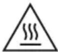
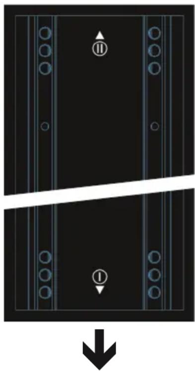
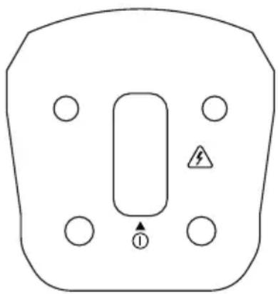
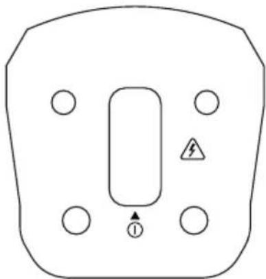
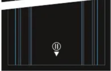
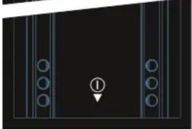
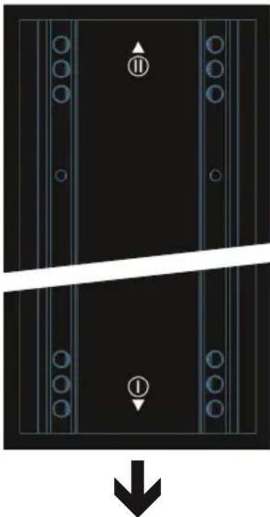
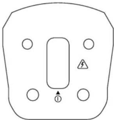
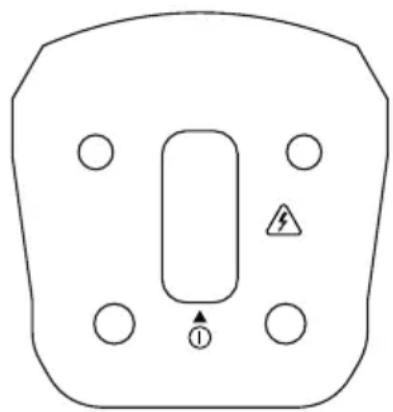
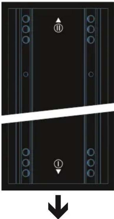
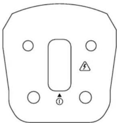
After setting up the subwoofer at the desired location, the lower column with the 8 midrange drivers is plugged into the subwoofer, and then the upper speaker column with 8 midrange drivers and the tweeters onto the lower column (please pay attention to the symbols on subwoofer and speaker columns, see drawing). Steel guiding pins facilitate the correct installation and ensure at the same time a secure hold. Using optional accessories, it is possible to mount the entire speaker pillar separately and attach it to a wall or a stand (two variants in each case).
IMPORTANT: In event of mounting on the subwoofer, always take care to ensure that both pillar elements are used and never only the upper pillar element. Otherwise, the automatic detection function will mute the system so as to avoid damage. In the event of separate mounting, always take care to ensure that both pillar elements are used and never only the upper pillar element. Otherwise, the automatic detection function will not work correctly and the system can potentially suffer damage.
The device allows both the volume of the entire system and the volume of the subwoofer in relation to the total volume to be adjusted separately. Source devices can be connected using both balanced and unbalanced cables (XLR / 6.3 mm jack / RCA / mini jack). The integrated 4-channel mixer offers a microphone input, a high-impedance instrument input for an electric guitar for example, an input for source devices with line level and furthermore a Bluetooth unit, which can be used in parallel to the 3.5 mm mini-jack input.
C. Upper speaker column
B. Lower speaker column
A. subwoofer
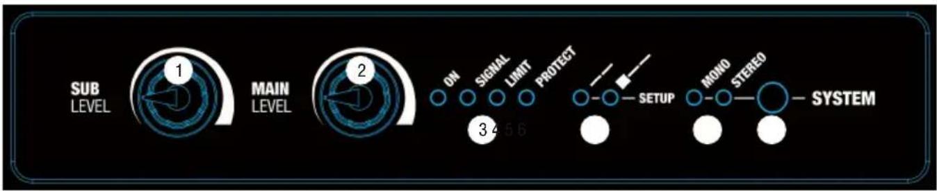
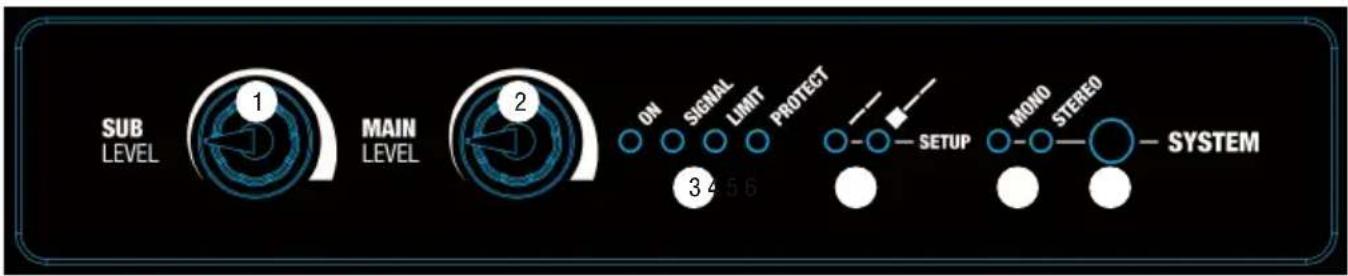
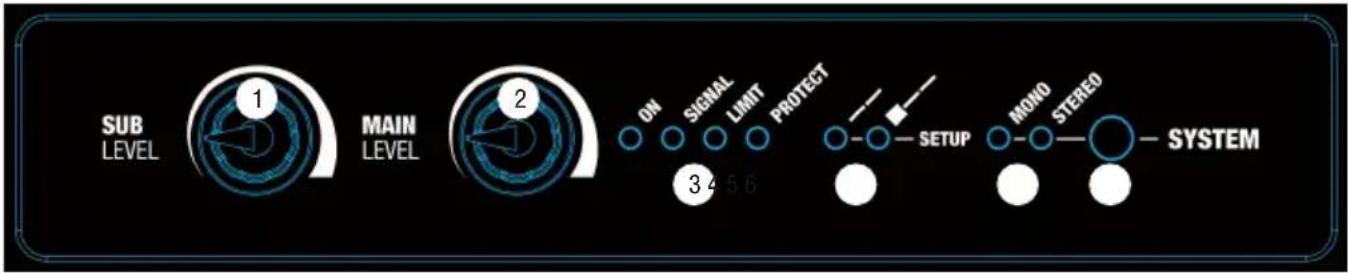
CONNECTIONS, CONTROLS AND INDICATORS

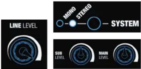
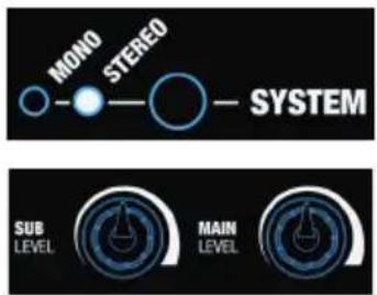
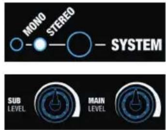
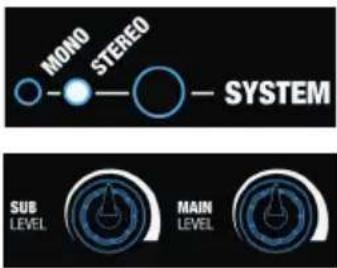
1 SUB LEVEL
Adjusting the volume ratio of the subwoofer to the column loudspeaker.
2 MAIN LEVEL
Overall volume adjustment. The subwoofer volume is also adjusted in accordance with the preset level on the SUB LEVEL controller.
3 INDICATOR LEDS
ON: Lights up once the system is properly connected to the power mains and switched on.
SIGNAL: Lights up as soon as an audio signal is present. The signal acquisition is performed before the MAIN LEVEL controller.
LIMIT: Lights up if the loudspeaker system is operating in the clipping range. A short flash of the LED is not critical. To protect the system, an excessive signal level is gently turned down by the built-in limiter. If the limiter LED lights up permanently or for longer periods, reduce the volume level. Failure to do so may result in a distorted sound and damage to the speaker system.
PROTECT: Lights up if the system is overloaded/overheated. The amplifiers are muted automatically. Upon reaching normal operating conditions, the device reverts to normal operating mode after a few minutes.
4 SETUP
LEDs to display the operating mode: wall or stand mounting, or subwoofer mounting. Optimised DSP settings are loaded automatically in accordance with the type of installation used for the speaker columns; the same adjustment automatically takes place on the corresponding LED as well.
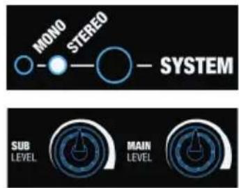
5 MONO / STEREO
LED display for the mono or stereo mode.
MONO: When using a single MAUI28G2 unit, select the Mono preset (press switch N 6 SYSTEM, LED indicator should signal MONO). An incoming stereo signal is now mono summed internally. You will find examples of system expansions and wiring in the CABLING EXAMPLES section of this user's manual.
STEREO: When using two MAUI28G2 units as a stereo set, select the Stereo preset (press switch N 6 SYSTEM, LED indicator should signal STEREO), use the line inputs left and right (RCA jacks LINE IN R + L N 9, or XLR / 6.3 mm jack combo sockets LINE IN R + L N 10) for controlling a playback device (CD player, mixer, etc.) and control the stereo expansion unit using the line output SYSTEM OUT. When using a Bluetooth® unit as a playback device (Smartphone, Tablet), also use the line output SYSTEM OUT for controlling the stereo expansion unit. You will find examples of system expansions and wiring in the CABLING EXAMPLES section of this user's manual.
6 SYSTEM
Switch to alternate between the operating modes Mono and Stereo. If the desired mode is activated, the corresponding LED display (N 5) will be lit.
7 MIC IN
Balanced microphone input with XLR / 6.3 mm jack combo socket (Mono). It is also possible to use an unbalanced microphone cable (Mono jack). The microphone input has a built-in low-cut filter (Low-cut) to suppress low-frequency noise and avoid feedback.
NOTE: There is no phantom power on the microphone input.
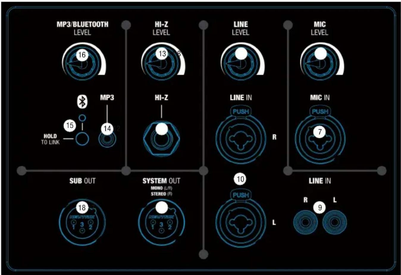
8 MIC LEVEL
Volume controller for the microphone channel. When turned to the left, the volume is lowered, when turned to the right, it is increased.
Unbalanced stereo line input with RCA sockets for connecting an external audio source (e.g. CD player, keyboard). Both line inputs N 9 and N 10 can be used simultaneously; the volume ratio must be set on the instrument, or on the external player.
10 LINE IN (XLR / 6.3 mm combo jack R + L)
Balanced stereo line input with XLR / 6.3 mm jack combo sockets for connecting a playback device (e.g. mixer, keyboard). Both line inputs N 9 and N 10 can be used simultaneously; the volume ratio must be set on the instrument, or on the external player.
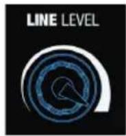
11 LINE LEVEL
Volume control for the line channel (N 9 and N 10). When turned to the left, the volume is lowered, when turned to the right, it is increased.
12 HI-Z INPUT
High-impedance mono input with 6.3 mm jack socket for acoustic or electric guitar. The HI-Z input has a built-in low-cut filter (Low-cut) to suppress low-frequency noise and avoid feedback.
13 HI-Z LEVEL
Volume control for the HI-Z channel. When turned to the left, the volume is lowered, when turned to the right, it is increased.
14 MP3 INPUT
Stereo line input with 3.5 mm jack socket for an MP3 player or other playback device. Both interfaces MP3 and Bluetooth ® can be used simultaneously; the volume ratio must be set on the instrument, or on the external player.
15 BLUETOOTH®
The mixer of the LDMAUI28G2 array system is equipped with Bluetooth, meaning that audio files from another Bluetooth device (e.g. Smartphone) can be played back on the LDMAUI28G2 array system (maximum distance between both devices about 10 metres). If no Bluetooth device is connected to the internal Bluetooth unit, the blue Bluetooth LED does not light up; the LED flashes at a frequency of about 3 Hz during pairing; if the Bluetooth LED is on permanently, then a Bluetooth connection is established and the track playback can be started. The volume is adjusted using the Bluetooth® volume controller (N 16) or on the source device.
To pair and connect the internal Bluetooth device with a Bluetooth-enabled device, press and hold the HOLD TO LINK button for approx. 3 seconds until the Bluetooth LED flashes (approx. 3 Hz), enable Bluetooth on your Bluetooth device and search for available devices on the user interface. Select "LD MAUI28G2" and pair your Bluetooth device with the internal Bluetooth device. The playback can now start. To end the connection, press and hold the HOLD TO LINK button again for approx. 3 seconds. If the Bluetooth connection is interrupted (e.g. the range is exceed), the Bluetooth LED goes out. Within approximately 90 seconds, the connection will automatically be restored (Bluetooth device back within range). When 90 seconds is exceeded, the Bluetooth module of the LD MAUI28G2 array system will automatically be disabled.
16 MP3/BLUETOOTH LEVEL
Volume controller for the MP3 channel and the Bluetooth unit. When turned to the left, the volume is lowered, when turned to the right, it is increased.
17 SYSTEM OUT
Balanced line output with 3-pin male XLR socket.
If the Mono mode is activated (point 5 MONO / STEREO), the sum of all input channels will be rendered in Mono.
Select the Mono mode and use the SYSTEM OUT line output to control another MAUI28G2 Mono unit.
If the Stereo mode is enabled (point 5 MONO / STEREO), the left channel of all stereo inputs (N 9, 10, 14 and 15) is processed internally and rendered by the MAUI28G2 array system, while the right channel of all stereo inputs is rendered by the SYSTEM OUT line output to control another MAUI28G2 unit externally as a stereo expansion. The sum of the Mono channels MIC IN and HI-Z IN is output in equal parts internally on the left and externally on the right.
Note: To achieve the same volume as well as the same sound as the main unit with the stereo expansion, turn the volume controller of the stereo expansion LINE LEVEL clockwise (maximum) and place the SUB LEVEL and MAIN LEVEL in the same position as the SUB LEVEL and MAIN LEVEL of the main unit.
18 SUB OUT
Balanced line input with male 3-pin XLR socket for connecting an external active subwoofer. The signal is now picked up after the SUB LEVEL volume controller; it is therefore dependent on the latter.
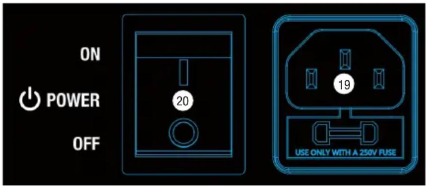
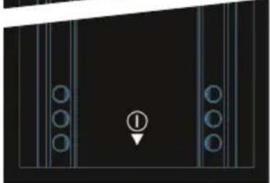
19 POWER CONNECTOR WITH FUSE HOLDER
IEC power socket with built-in fuse holder. An appropriate power cord is included in the delivery.
IMPORTANT INFORMATION: Replace the fuse only with a fuse of the same type and rating. Please observe the label on the housing. If the fuse blows repeatedly, please contact an authorised service centre.
20 POWER ON / OFF
On / Off switch for the power supply of the device.
WHAT DOES LD SYSTEMS DynX® DSP STAND FOR?
DSP stands for Digital Signal Processing, DynX® comprises the Limiter, EQ, Compressor and Crossover features. The digital signal processing ensures maximum audio performance with maximum clarity and protects the PA system from overload.
WHAT EXACTLY DOES DynX® DSP DO?
The Limiter function protects the speakers and prevents distortions caused by overload. Separate limiters for bass midrange and high range attenuate the signal when the level exceeds a value which could have a negative effect. Each limiter is optimised for one of the three seamlessly contiguous frequency ranges (multi-band limiter). The system can be operated in this manner with a higher overall sound pressure as extreme peaks are automatically lowered, so that the total volume does not need to be reduced. The Multiband EQ works over the entire frequency range and optimises the overall sound of the system.
The crossovers divide the audio signal according to the frequency range of the respective speakers, namely the subwoofer or the mids and tweeters of the array column. The amplitude and running-time optimisation of the crossover ensures that all frequencies are output evenly and reach the listener at the same time.
CABLING EXAMPLES
Example of Mono operating mode.
![graph TD A["MONO STEREO SYSTEM"] --> B["Micro-In keyboard"] B --> C["Micro-In keyboard with keyboard"] C --> D[" Piano Key"] style A fill:#f9f,stroke:#333 style B fill:#ccf,stroke:#333 style C fill:#cfc,stroke:#333 style D fill:#fcc,stroke:#333](/content/2026/04/587228/images/277b036db0d49cf2aa69c28846c38cbf0030910f579db6edec21712aa77f1644.jpg)
Example of Stereo operating mode.
Main unit Stereo expansion


Maximum Same settings as on the main unit
![graph TD A["Smartphone"] -->|Wireless Signal| B["Microphone"] B --> C["Microphone"] C --> D["Line IN PUSH"] D --> E["Line IN PUSH L"] E --> F["Audio System"] F --> G["Audio System OUT"] style A fill:#f9f,stroke:#333 style B fill:#ccf,stroke:#333 style C fill:#cfc,stroke:#333 style D fill:#fcc,stroke…](/content/2026/04/587228/images/f6112865f21900d6da02a8a64a7989c80abb8fc0875da4ff009def1e9dc613f3.jpg)
OPTIONAL ACCESSORIES
LDM28G2SATBAG: Carrying bag for LDMAUI28G2 speaker column
LDM28G2SUBPC: Protective cover for LDMAUI28G2 subwoofer
LDM28G2CB: Castor board for LDMAUI28G2 subwoofer
LDMG2SPS: Stand for LDMAUIG2 speaker column, black
LDMG2SPSW: Stand for LDMAUIG2 speaker column, white
LDMG2IK1: Installation Set for wall mounting the LDMAUIG2 speaker column (flat mounting) - black
LDMG2IK1W: Installation Set for wall mounting the LDMAUIG2 speaker column (flat mounting) - white
LDMG2IK2: Installation Set for wall mounting the LDMAUIG2 speaker column (adjustable angle) - black
LDMG2IK2W: Installation Set for wall mounting the LDMAUIG2 speaker column (adjustable angle) - white
TECHNICAL SPECIFICATIONS
| Model Name: LDMAUI28G2(W) | |
| Product Type: Column PA system | |
| Type: Active | |
| Colour: LDMAUI28G2 - black | LDMAUI28G2W - white |
| Max. SPL (peak): 126 dB | |
| Frequency Response: | 45 - 20,000 Hz |
| Dispersion Angle (H x V): | 120° x 20° |
| Overall Height: 2059 mm | |
| Weight: | 30.9 kg |
| Features: | DSP-based signal processing, excellent sound dispersion, bluetooth audio streaming, 4-channel mixer on board, mono/stereo application, automatic DSP adjustment, available in black and white, wall mount and floor stand available |
| subwoofer | |
| Low/mid Driver Dimensions: | 2 x 8" |
| Low/mid Driver Dimensions (mm): 2 x 203 mm | |
| Woofer Magnet: | Ferrite |
| Woofer Brand: | Custom made |
| Woofer Voice Coil: | 2" |
| Woofer Voice Coil (mm): | 50.8 mm |
| Cabinet Construction: | Vented |
| Cabinet Material: | 15 mm plywood |
| Cabinet Surface: | Texture paint |
| Subwoofer Width: | 370 mm |
| Subwoofer Height: | 484 mm |
| Subwoofer Depth: | 480 mm |
| Subwoofer Weight: | 19.7 kg |
| Mid/Hi System | |
| Midrange Size: | 16 x 3" |
| Midrange Size: | 16 x 76.2 mm |
| Midrange Magnet: | Ferrite |
| Midrange Brand: Custom made | |
| Midrange Voice Coil: | 1" |
| Midrange Voice Coil: | 25.4 mm |
| Horn: BEM optimized CD wave guide | |
| Tweeter Dimensions: | 2 x 1" |
| Tweeter Dimensions (mm): | 25.4 mm |
Tweeter Magnet: Neodymium
Tweeter Brand: Custom made
Tweeter Voice Coil: 1"
Tweeter Voice Coil (mm): 25.4 mm
Loudspeaker Inputs: 1
Speaker Input Connections: Custom-made multi-pin
Cabinet Construction Mid/High: Closed
Mid/Hi System Cabinet Material: Aluminium
Mid/Hi System Cabinet Surface: HD coating
Mid/Hi System Width: 96 mm
Mid/Hi System Height: 780/ 795 mm
Mid/Hi System Depth: 104 mm
Mid/Hi System Weight: 5.6 / 5.6 kg
Amplifier Module (integrated in Subwoofer)
| Amplifier: | 3-way Class D |
| Amplifier Output Power System (RMS): | 1000 W |
| Amplifier Output Power System (Peak): | 2000 W |
| Protection Circuits: | Thermal overload, multiband limiter, short circuit, DC protection |
| Cooling: | Convection |
| Controls: | Mic level, sub level, line level, MP3/Bluetooth level, Hi-Z level, main level, mono/stereo switch, bluetooth button |
| Indicators: | on, signal, limit, protect, mono/stereo, setup |
| Power Connector: | IEC (power cable included) |
| Operating Voltage: | Switching power supply, 100 V AC - 120 V AC, 50 - 60 Hz, 200 V AC - 240 V AC, 50 - 60 Hz (automatic conversion) |
| Power Consumption Off / On / Max.: | 0 / 11 / 600 W |
| Ambient Temperature (in operation): | 0°C - 40°C |
| Humidity Range: | 10% - 80% rel. (non condensing) |
| Line Inputs: | 2 x stereo |
| Line Input Connectors: | RCA, XLR/6.3 mm jack |
| Line Outputs: | 2 (1x System Out, 1x Sub Out) |
| Line Output Connectors: | XLR |
| Mic Inputs: | 1 |
| Mic Input Connectors: | XLR / 6.3 mm jack |
| MP3 Inputs: | 1 |
| MP3 Input Connectors: | 3.5 mm jack |
| HI-Z Inputs: | 1 |
| Hi-Z Input Connectors: | 6.3 mm jack |
| Loudspeaker Outputs: | 1 |
| Speaker Output Connections: | custom-made multi-pin |
DSP Characteristics
| Bit depth AD/DA Converter: | 24 bit |
| Internal Sampling Frequency: | 48 kHz |
| Signal/noise ratio: | 100 dB |
MANUFACTURER'S DECLARATIONS
MANUFACTURER'S WARRANTY & LIMITATIONS OF LIABILITY
You can find our current warranty conditions and limitations of liability at: http://www.adamhall.com/media/shop/downloads/documents/manufacturersdeclarations.pdf. To request warranty service for a product, please contact Adam Hall GmbH, Daimler Straße 9, 61267 Neu Anspach / Email: Info@adamhall.com / +49 (0)6081 / 9419-0.

CORRECT DISPOSAL OF THIS PRODUCT
(valid in the European Union and other European countries with a differentiated waste collection system)
This symbol on the product, or on its documents indicates that the device may not be treated as household waste. This is to avoid environmental damage or personal injury due to uncontrolled waste disposal. Please dispose of this product separately from other waste and have it recycled to promote sustainable economic activity. Household users should contact either the retailer where they purchased this product, or their local government office, for details on where and how they can recycle this item in an environmentally friendly manner. Business users should contact their supplier and check the terms and conditions of the purchase contract. This product should not be mixed with other commercial waste for disposal.
FCC STATEMENT
This device complies with Part 15 of the FCC Rules. Operation is subject to the following two conditions:
(1) This device may not cause harmful interference, and
(2) This device must accept any interference received, including interference that may cause undesired operation
CE Compliance
Adam Hall GmbH states that this product meets the following guidelines (where applicable):
R&TTE (1999/5/EC) or RED (2014/53/EU) from June 2017
Low voltage directive (2014/35/EU)
EMV directive (2014/30/EU)
RoHS (2011/65/EU)
The complete declaration of conformity can be found at www.adamhall.com.
Furthermore, you may also direct your enquiry to info@adamhall.com.
DEUTSCH
A. Subwoofer
WAS BEDEUTET LD SYSTEMS DynX® DSP?
OPTIONALES ZUBEHÖR
APPAREILS RELIÉS AU SECTEUR
CONNECTEURS, CONTRÔLES ET INDICATEURS

1 SUB LEVEL
QUE SIGNIFIE LE SIGLE «DSP DynX®» LD SYSTEMS ?


(Valid in the European Union and other European countries with waste separation)
B. Columna inferior
A. Subwoofer
CONEXIONES, CONTROLES E INDICADORES

1 SUB LEVEL
A. Subwoofer
ZŁĄCZA, ELEMENTY OBSŁUGI I WSKAŹNIKI
1 SUB LEVEL
CZYM JEST TECHNOLOGIA DynX® DSP FIRMY LD SYSTEMS?


CONNESSIONE E ACCENSIONE

A. Subwoofer

CONNESSIONI, ELEMENTI DI COMANDO E VISUALIZZAZIONE
1 SUB LEVEL
B. 下部
扬声器音柱
A. 重低音音箱
接口、操作和显示元件
① 低音音量
立体声运行方式示例
主单元 立体声扩展
最大 与主单元设置相同
![graph TD A["Smartphone"] -->|Wireless Signal| B["Device 1"] B --> C["Microphone"] C --> D["Line IN PUSH"] D --> E["Line IN PUSH R"] E --> F["Digital Audio System"] F --> G["Digital Audio System"] G --> H["Line IN PUSH L"] H --> I["System OUT HAND-L (STERED F)"] I --> J["Digital Audio System"] J -->…](/content/2026/04/587228/images/b05887e1da8ac1506d5337701506f607c13793921c3b023eb716a692879108f7.jpg)
可选配件
LDM28G2SATBAG:LDMAUI28G2扬声器音柱的便携包
LDM28G2SUBPC:LDMAUI28G2重低音音箱的保护罩
連接、操作及顯示元件

1 超低音電平 (SUB LEVEL)
16 MP3/BLUETOOTH LEVEL (MP3/藍牙電平)
立體身歷聲模式示例
主單元 立體身歷聲擴展
最大 與主單元的相同的設定
![graph TD A["Smartphone"] -->|Wireless Signal| B["Device 1"] C["HOLD TO LINK"] --> B D["MIC IN PUSH"] --> B E["LINE IN PUSH"] --> B F["SYSTEM OUT MIND L/F STEREO F"] --> B G["LINE IN PUSH L"] --> B B --> H["Keyboard"] style A fill:#f9f,stroke:#333 style C fill:#f9f,stroke:#333 style D fill:#ccf,strok…](/content/2026/04/587228/images/437739ac80d83cf838c9f2c8a5600ea3fb94d384ba06d387e71c4750495ee4c4.jpg)
可選附件
LDM28G2SATBAG:LDMAUI28G2 揚聲器音柱的運輸箱
LDM28G2SUBPC:LDMAUI28G2低音炮防護罩


- MAUI 28 G2
- CONTENTS / INHALTSVERZEICHNIS / CONTENU / CONTENIDO / TREŚĆ / CONTENUTO
- 目录 / 目錄
- ENGLISH
- DEUTSCH
- PREVENTIVE MEASURES
- FOR EQUIPMENT THAT CONNECTS TO THE POWER MAINS
- CAUTION
- CAUTION! HIGH VOLUMES IN AUDIO PRODUCTS
- INTRODUCTION
- GENERAL INSTRUCTIONS
- SETUP
- CONNECTIONS, CONTROLS AND INDICATORS
- 1 SUB LEVEL
- 2 MAIN LEVEL
- 3 INDICATOR LEDS
- 4 SETUP
- 5 MONO / STEREO
- 6 SYSTEM
- 7 MIC IN
- 8 MIC LEVEL
- 10 LINE IN (XLR / 6.3 MM COMBO JACK R + L)
- 11 LINE LEVEL
- 12 HI-Z INPUT
- 13 HI-Z LEVEL
- 14 MP3 INPUT
- 15 BLUETOOTH®
- 16 MP3/BLUETOOTH LEVEL
- 17 SYSTEM OUT
- 18 SUB OUT
- 19 POWER CONNECTOR WITH FUSE HOLDER
- 20 POWER ON / OFF
- WHAT DOES LD SYSTEMS DYNX® DSP STAND FOR
- WHAT EXACTLY DOES DYNX® DSP DO
- CABLING EXAMPLES
- OPTIONAL ACCESSORIES
- MANUFACTURER'S DECLARATIONS
- MANUFACTURER'S WARRANTY & LIMITATIONS OF LIABILITY
- CORRECT DISPOSAL OF THIS PRODUCT
- FCC STATEMENT
- CE COMPLIANCE
- WAS BEDEUTET LD SYSTEMS DYNX® DSP
- OPTIONALES ZUBEHÖR
- APPAREILS RELIÉS AU SECTEUR
- CONNECTEURS, CONTRÔLES ET INDICATEURS
- QUE SIGNIFIE LE SIGLE «DSP DYNX®» LD SYSTEMS
- CONEXIONES, CONTROLES E INDICADORES
- ZŁĄCZA, ELEMENTY OBSŁUGI I WSKAŹNIKI
- CZYM JEST TECHNOLOGIA DYNX® DSP FIRMY LD SYSTEMS
- CONNESSIONE E ACCENSIONE
- CONNESSIONI, ELEMENTI DI COMANDO E VISUALIZZAZIONE
- 下部
- 扬声器音柱
- 接口、操作和显示元件
- ① 低音音量
- 可选配件
- 連接、操作及顯示元件
- 1 超低音電平 (SUB LEVEL)
- 16 MP3/BLUETOOTH LEVEL (MP3/藍牙電平)
- 可選附件
Brand : LD Systems
Model : MAUI 28 G2
Category : Loudspeaker