
PGA4370 - Cooker Pando - Free user manual and instructions
Find the device manual for free PGA4370 Pando in PDF.
| Product Type | Built-in Gas Hob |
| Brand | Pando |
| Model | PGA4370 |
| Category | Gas Hob |
| Dimensions (W x D x H) | 553 x 473 x 63.5 mm (overall) |
| Weight | Approximately 10 kg |
| Power Supply | Gas (G20/G30/G31) and 220-240 V~ |
| Total Power (gas) | 10.95 kW (G20) |
| Number of Burners | 5 |
| Burner Types | 1 ultra-rapid (4000 W), 1 rapid (2800 W), 2 semi-rapid (1750 W and 1400 W), 1 auxiliary (1000 W) |
| Ignition | Automatic electric ignition |
| Safety | Safety thermocouples on each burner |
| Surface Material | Ceramic glass |
| Compatible Gas Type | Butane (G30), Propane (G31), Natural gas (G20) |
| Nominal Gas Pressure | G20: 20 mbar; G30: 28-30 mbar; G31: 37 mbar |
| Electrical Supply Voltage | 220-240 V~ |
| Frequency | 50/60 Hz |
| Protection Class | Class I (earth connection) |
| Maintenance | Clean the burners and ceramic glass surface with soapy water; avoid metal scouring pads |
| Warranty | 3 years |
Frequently Asked Questions - PGA4370 Pando
User questions about PGA4370 Pando
0 question about this device. Answer the ones you know or ask your own.
Ask a new question about this device
Download the instructions for your Cooker in PDF format for free! Find your manual PGA4370 - Pando and take your electronic device back in hand. On this page are published all the documents necessary for the use of your device. PGA4370 by Pando.
USER MANUAL PGA4370 Pando
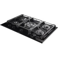
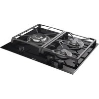
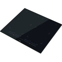
natural_image
Modern black gas stove with four fuses and a Pando appliance, placed on a white countertop (no text or symbols visible)Pando integralcooking
PGA - 4260
PGA - 4370
PGA - 4491

ENGLISH User and installation manual Warranty certificate
The Global Kitchen Partner
Quality Management System Certification

ISO 14001:2015 - ES20/208675
Environmental Management System Certification
natural_image
Simple line drawing of a trash bin with no text or symbols
DEL MEDIOAMBIENTE Y TRATAMIENTO DEL RESIDUO
USO DEL PRODUCTO....12
Quemadores....12
CONSEJOS PARA AHORRAR ENERGÍA Y CUIDADO DE RECIPIENTES....14
PROBLEMAS COMUNES Y SOLUCIONES....15
INSTALACIÓN ....16
Inserción De La Placa....16
natural_image
Simple line drawing of a kitchen scene with a cooking pot and a stand (no text or symbols)
natural_image
Simple line drawing of two cooking pots with no text or symbols
natural_image
Two line drawings of a cooking pot with steamers and a crossed-out stand (no text or symbols)PROBLEMAS COMUNES Y SOLUCIONES
natural_image
Close-up of a metallic object with a curved surface and a labeled point E (no text or symbols on the object itself)natural_image
Close-up of a layered electronic component with labeled points A and B, showing internal structure and mounting details (no text beyond labels)Conexión Del Gas
natural_image
Line drawing of a hand using a tool to clean or inspect a circular component (no text or symbols)natural_image
Close-up of a hand using a black plastic tool to clean or paint on a reflective surface (no text or symbols visible)MANTENIMIENTO
natural_image
Simple line drawing of a curved pipe or tube with a base and a labeled point B (no text or symbols)ADVERTENCIAS:
natural_image
Simple line drawing of a trash bin with no text or symbols
natural_image
Simple line drawing of a kitchen scene with a cooking pot and a stand (no text or symbols)
natural_image
Simple line drawing of two cooking pots with no text or symbols
natural_image
Two line drawings of a cooking pot with steamers, one crossed out by a diagonal line (no text or symbols)PROBLEMAS E SOLUÇÕES COMUNS
natural_image
Close-up of a metallic object with a curved surface and a labeled point E (no text or symbols on the object itself)natural_image
Close-up of a layered electronic component with labeled parts A and B (no text or symbols beyond labels)natural_image
Diagram showing a wall corner with brick wall and a marked point (*) indicating a location or feature, no text or symbols present.Ligação De Gás
natural_image
Line drawing of a hand using a tool to clean or inspect a circular component (no text or symbols)natural_image
Close-up of a hand holding a black plastic clip against a blurred background (no text or symbols visible)MANUTENÇÃO
natural_image
Pure diagram of a curved pipe or tube with a base, no text or symbols presentADVERTÊNCIAS:
natural_image
Simple line drawing of a trash bin with no text or symbols
PROTECTION DE L'ENVIRONNEMENT ET TRAITEMENT DES DÉCHETS
natural_image
Simple line drawing of a kitchen scene with a cooking pot and a stand (no text or symbols)
natural_image
Simple line drawing of two cooking pots with no text or symbols
natural_image
Two simple line drawings of a cooking pot with steamers, one crossed out by a diagonal line (no text or symbols)PROBLÈMES COURANTS ET SOLUTIONS
natural_image
Close-up of a metallic object with a droplet and label 'E' (no other text or symbols visible)natural_image
Close-up of a metallic panel with labeled points A and B, showing internal structure and grid pattern (no text or symbols beyond labels)Instructions d'installation IMPORTANTES
Important :
Raccordement Au Gaz
natural_image
Hand holding a tool above a circular mechanical component (no text or symbols visible)natural_image
Close-up of a hand holding a black plastic clip against a blurred background (no text or symbols visible)ENTRETIEN
natural_image
Simple line drawing of a curved pipe or duct with a base and a labeled point B (no text or symbols)MISES EN GARDE :
Pando reserves the right to change or cancel any measure of the items in the manual, without prior notice, and is not responsible for any errors or omissions that may occur in the manual.
Technical specifications are valid except for typographical errors or omissions.
the images and contents of this manual are the exclusive property of Pando -
INOXPAN S.L., therefore the use of images and total or partial reproduction without prior written authorization is strictly prohibited.
THE IMAGES SHOWN IN THIS MANUAL ARE NOT CONTRACTUAL.
Pando Technical Management reserves the right to modify, alter or improve the technical drawings shown in this manual without prior notice.
Dear customer... First of all, we would like to thank you for your confidence you have placed your trust in us by purchasing one of our products. We are sure that you have made the right decision.
At Pando, not only do we offer top quality products, but we also have a large team of professionals who will assist and advise you with any queries you may have during installation or operation.
We invite you to visit our website (www.pando.es) to get to know us better and where you will be able to see our full range of products with complete commercial and technical information.
We also show you our collection of essential appliances in any home. Appliances such as our collection of high-performance Ovens and Microwaves, Induction and Gas Hobs that will allow you to take your recipes to another level, Wine cellars and ageing cellars to maintain and preserve your wines in the best conditions and integrated dishwashers with the latest technology.
All this under a brand with a very long history of more than 40 years in the market, which produces its products as a true craftsman. Our products reflect the best of our experience in order to satisfy all your needs.
We sincerely hope that you will have fun, experience and enjoy the comfort and capabilities of what is already your new kitchen ally.
Many Thanks
El equipo de Pando
ENVIRONMENTAL PROTECTION
The symbol on the product or its packaging indicates that this product cannot be disposed of like normal domestic waste. The product must be handed over at a collection point for recycling electrical and electronic equipment. If you ensure that this product is correctly disposed of, you will help to avoid the possible negative environmental and public health effects that could arise from incorrect disposal. For more detailed information about recycling this product, please contact your city authorities, the domestic waste service or the establishment where you purchased it. This electrical appliance is marked in compliance with European Directive 2012/19/EU on electrical and electronic appliance waste (WEEE).
COLLECTION OF
HOUSEHOLD APPLIANCES
natural_image
Simple line drawing of a trash bin with no text or symbols
ENVIRONMENTAL PROTECTION AND WASTE TREATMENT
DISPOSAL OF THE PACKAGING. The packaging is marked with in Green Dot.
In its commitment to the protection of the environment and in compliance with the provisions of the European Directive 94/62 / EC on packaging and packaging waste and the derived Law 22/2011 on Contaminated Residues and Soils, Pando entrusts entities of social economy an Integrated Management System, responsible for the periodic collection at the consumer's home or in its vicinity of used packaging and packaging waste for subsequent treatment.
To remove all packaging materials such as cardboard, expanded polyurethane, and film, use the appropriate containers.
This ensures the correct treatment and reuse of packaging materials.
INDEX
SAFETY INSTRUCTIONS 86
DESCRIPTION OF THE HOB....89
USE OF THE PRODUCT 90
Burners 90
ENERGY SAVING TIPS AND CONTAINER CARE....92
COMMON PROBLEMS AND SOLUTIONS....93
INSTALLATION....94
Plate Insertion....94
Fitting dimensions....94
PGA 4491 94
PGA 4260 94
PGA 4370 94
Plate Fixing....96
Ventilation Of Premises 97
Location and Aeration....97
Gas Connection....98
CLEANING....101
Worktop 101
Ceramic hob 102
MAINTENANCE....102
Replacement Of Injectors. 102
Burner Arrangement 103
Types And Sections Of Power 104
Cables....104
Please read these instructions carefully. Only then can you use your appliance safely and correctly. We strongly recommend that you keep the instruction manual and installation instructions for future use or for subsequent owners
Please Note That...
- Should only be installed in a kitchen.
- Check if the appliance shows any damages immediately after unpacking.
- Do not connect the appliance if it is damaged. Only an authorized professional can connect the appliance.
- If the power cable is damaged, it must be replaced by the manufacturer, their technical service, or similarly qualified individuals to avoid risks.
- Damages caused by incorrect connection are not covered by the warranty.
- Adequate ventilation of the room must be provided if a kitchen hood and appliances powered by gas or other fuel are used simultaneously (not applicable to appliances exclusively designed to discharge air into the room).
- Use this appliance only indoors and for culinary purposes.
- During its use, do not leave the gas hob unattended, especially if used by children or individuals with reduced physical, sensory, or mental capabilities, or lack of experience and knowledge. These individuals should only use the gas hob if instructed by a responsible person on how to safely operate the appliance and have understood the associated dangers.
- This appliance should not be used by children under 8 years old, and from that age, if used, it should be supervised and kept at a safe distance, both from the gas hob and the power cable.
- There is a risk of fire if cleaning is not carried out according to the instructions.
- Regulations regarding air evacuation must be respected.
SAFETY INSTRUCTIONS
• Accumulations of grease deposits can cause fires.
- Upon delivery of the appliance, remove the packaging within 24 hours and verify that it is in good condition by visually inspecting its overall external appearance. In case of any anomalies or defects, do not install it and report it immediately to your retailer or installer within 24 hours of receipt.
- The gas hob has been manufactured for normal domestic use. It should not be used for industrial, professional, or other purposes different from those for which it has been designed.
- Pando will not provide any warranty for consequences and damages resulting from improper installation or misuse of the appliance.
- To avoid risks, manipulation of the appliance is prohibited if the power cable is damaged; it must be replaced by the manufacturer through the authorized service technician. Repairs involving manipulation of the appliance or its components must be carried out exclusively by an authorized specialized service technician.
- Never attempt to modify the characteristics of this appliance, as it constitutes a danger and automatically voids the manufacturer's warranty.
- Disconnection after installation must be allowed and accessible to the user.
- Duct installation must comply with current standards regarding ventilation.
- Improper and unauthorized manipulation of the gas hob, such as modifying, cutting, or perforating its body, structure, or electrical wiring, or the internal or external motor unit and peripherals, is expressly prohibited. This violation would result in the automatic loss of the manufacturer's warranty and exempt them from any liability for potential personal or material damages.
- With the constant intention of improving our products, we reserve the right to make all modifications to their technical, functional, or aesthetic characteristics resulting from their evolution.
SAFETY INSTRUCTIONS
IMPORTANT: During installation, before making the electrical connection to your gas hob, always disconnect the power panel that will supply it (differential or thermal-magnetic switch from the general electrical panel of the house).
- The negative pressure in the room should not exceed 0.04 mbar. This condition allows for optimal operation. To achieve this environment, it is necessary to have a permanent air inlet to avoid air tightness (it is advisable to have a ventilation grille for this purpose). Windows and doors are not valid for this.
- The electrical power supply must be stable and meet the electrical requirements indicated (refer to the appliance's nameplate). If it is not stable and receives a supply with voltage, current, or frequency variations, such as harmonics, transients, voltage sags, overloads, electrical storms, etc., the gas hob may malfunction or even fail, and the repair will not be covered by the warranty. In such a case, it is necessary to disconnect the hob and contact an electrician or the power company to address the electrical supply issue.
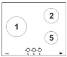
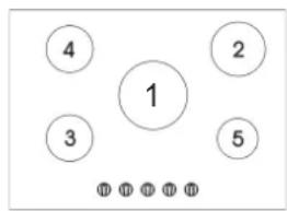
DESCRIPTION OF THE HOB
- ∅133mm 4000 W ultra high-speed burner
- ∅100mm 2800 Watt fast burner
- ∅55mm 1000 W auxiliary burner
- Grill
- Burner control n° 1
-
Burner control n° 5
-
Burner control n° 2
- ∅75mm 1400 W Semi-fast burner Reduced
- ∅75mm 1750 W Semi-fast burner
- Burner control n° 4
- Burner control n° 3
USE OF THE PRODUCT
Burners
A diagram indicating the corresponding burner is silk-screened on the front panel at the top of each control. Once the gas mains tap or gas cylinder tap has been opened, light the burners according to the following instructions:
• Automatic electric ignition
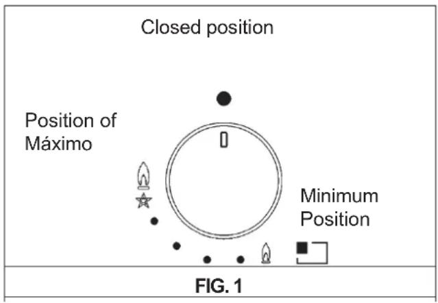
Press the knob for the burner you wish to use and turn it to the left, turn it to the maximum position (large flame fig. 1) and then press the knob all the way down.
- Ignition of burners fitted with safety thermocouples
For burners fitted with a safety thermocouple, turn the knob on the burner you wish to use to the left, turn it to the maximum position (large flame fig. 1) until you feel a small stop, then press the knob and repeat the above procedure.
Once switched on, press and hold the knob for at least 10 seconds.
If the flames go out unintentionally, close the burner control knob and wait at least 1 minute before attempting to relight the burner.
How to use the burners
To obtain maximum performance with minimum gas consumption, remember the following instructions:
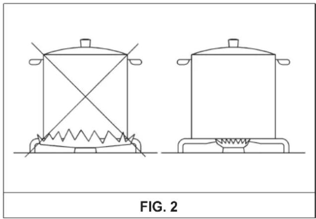
• Use suitable pots for each burner (see table below and fig. 2).
- Once boiling has been achieved, turn the knob to the minimum position (small flame fig. 1).
• Always use pots with lids.
• Always use pans with flat bottoms.
| Burner Power W Pot ∅ (cm) | |
| Ultra-fast 4000 24/26 | |
| Fast 2800 20/22 | |
| Semi-fast 1750 16/18 | |
| Semi-fast R. 1400 16/18 | |
| Auxiliary 1000 10/14 |
natural_image
Line drawings of two cooking pots with steamers, labeled FIG. 2 (no text or symbols on the pots themselves)WARNINGS AND ADVICE TO THE USER
- In the event of a power failure, the burner can be lit with matches.
- When using the appliance, do not leave it unattended and make sure that children are not in the vicinity. In particular, make sure that the handles of the pans are in the correct position and carefully check that food containing oils or fats is cooked, as these are easily flammable.
- Do not use "spray" near the equipment when it is operating.
- If the hob is fitted with a lid, all food residues must be removed from its surface before opening it. If the appliance is fitted with a glass lid, it may explode if heated. Turn off and allow all burners to cool down before closing it.
- Do not scrape the pans on the glass because may damage the surface.
- We do not recommend the use of containers whose diameter exceeds the perimeter of the plate.
- The use of a gas cooker produces heat and humidity in the room where it is installed. It is therefore necessary to ensure that the room is well ventilated by keeping the natural ventilation opening free (see installation section) and by activating a ventilation device such as an extractor hood or electric fan (see installation section).
- If the appliance is used intensively and for long periods of time, additional ventilation may be necessary; in this case, a window can be opened or the ventilation can be improved by increasing the power of the mechanical suction, if available.
- Do not attempt to modify the technical characteristics of the product, as this could be dangerous.
Attention
During operation, the gas hob becomes very hot in the cooking zones:
Keep the children away!
- If it is decided to stop using this appliance (or to replace an old model) before scrapping it, it is recommended to render it unusable in accordance with the current regulations on health protection and environmental pollution protection, by removing the parts that could be dangerous, especially for children, who could use the appliance out of use for playing.
- Do not use the appliance barefoot.
- The manufacturer cannot be held liable for any damage resulting from improper, erroneous or unreasonable use.
- During and immediately after operation, some parts of the hob reach very high temperatures: avoid touching them.
• After using the gas hob, make sure that the rotary knobs are in the closed position and close the main tap of the gas distribution line or the gas cylinder tap.
- In case of malfunctioning of the gas valves, please contact the assistance service.
- Do not touch the appliance with wet or damp hands or feet.
Attention
In the event of glass breakage on the hob: Immediately switch off all fires and electric heating elements, then disconnect the power supply to the appliance, do not touch the surface of the appliance and do not use the appliance.
ENERGY SAVING TIPS AND CONTAINER CARE
natural_image
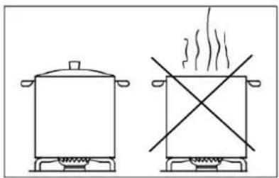
Two simple line drawings of a cooking pot and a heating box with a crossed-out cross (no text or symbols)- To avoid wasting energy, do not cook without a lid or with the lid off.

natural_image
Two identical line drawings of a cooking pot with steamers, no text or symbols present• Centre the pan well on the burner.
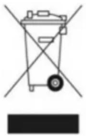
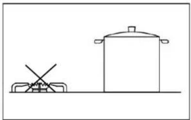
- Do not place large containers close to the controls, as they will could be damaged by overheating

natural_image
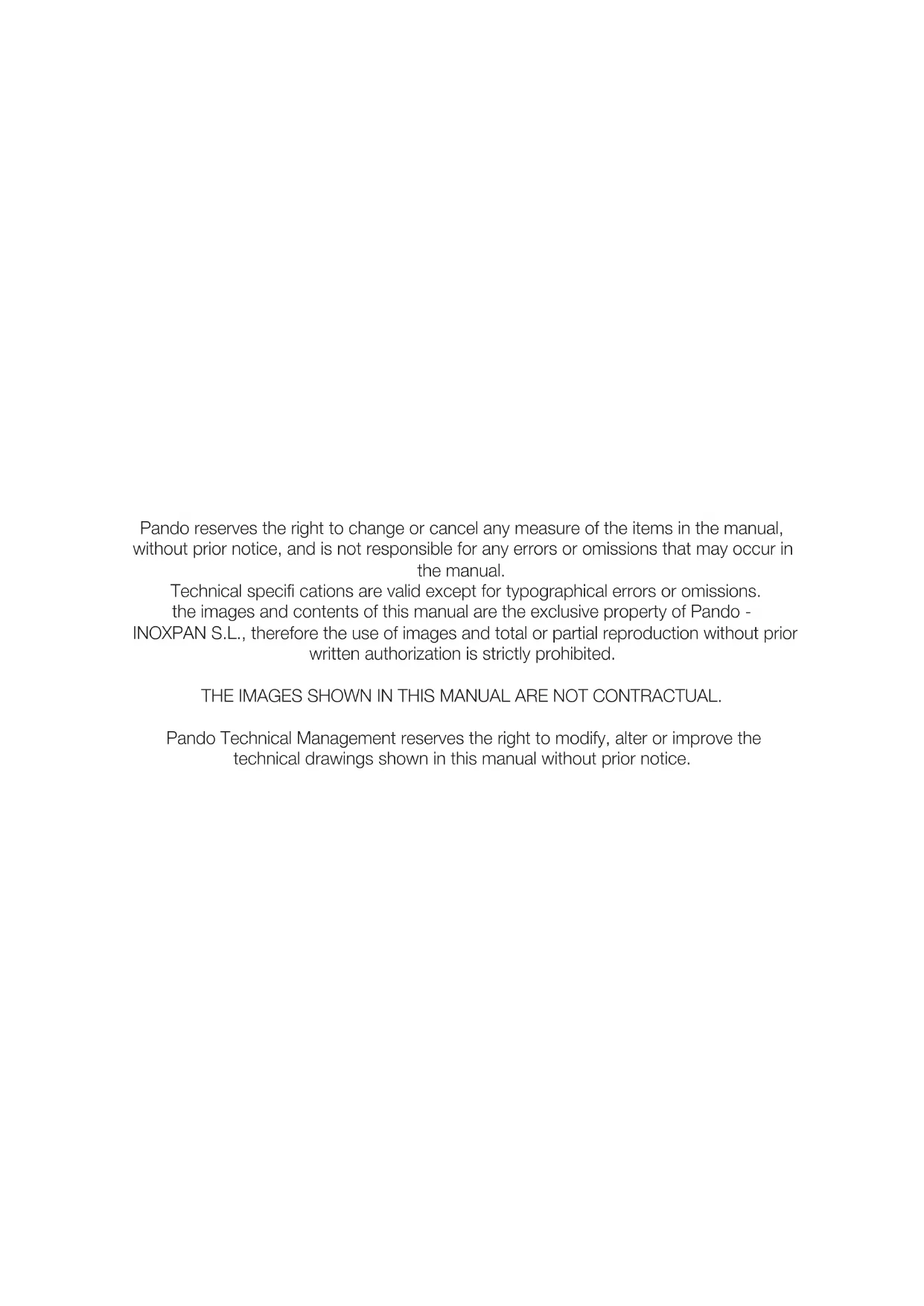
Two simple line drawings of a gas stove and a storage tank with no text or symbols- Never place the pan directly on the burner, always place it on the grills. Make sure that the grills are properly positioned before use.
- Handle the containers carefully on the hotplate, do not hit the hotplate and do not place excessive weights on the hotplate.
- Do not remove the container and leave the fire burning, this may cause a fire. This could lead to serious damage.
- Use the appropriate size burner for each vessel. Do not use containers smaller than the size of the burner, the flame must not come into contact with the sides of the container
• Always use containers with a good, flat, thick base. Deformed containers may tip over

natural_image
Simple line drawing of a cooking pot and a cooking pot with a crossed handle (no text or symbols)
natural_image
Simple line drawing of two cooking pots with no text or symbols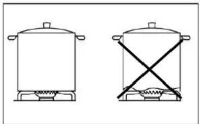
natural_image
Two simple line drawings of a cooking pot with steamers and a crossed-out stand (no text or symbols)COMMON PROBLEMS AND SOLUTIONS
| ProblemCauseSolution | ||
| The burner flame is not uniform. | Presence of dirt inside the burner crown. | Clean the burner crown foreign bodies. |
| Incorrect gas adjustment. | Call the Technical Helpdesk ca Official Pando. | |
| Burner flame suddenly changes / explodes. | Incorrect assembly of burner components. | Assemble the burner components correctly. |
| The flame takes too long to ignite. | Incorrect assembly of burner components. | Assemble the burner components correctly. |
| The flame goes out after ignition. | Release of the precipitated ignition control | Clean the grates and burner components with suitable metal cleaning agents. |
| Thermocouple problems | Move the thermocouple | |
| Call the Technical Helpdesk ca Official Pando. | ||
| Change of colour of the grids in the cooking zone. | Normal situation, caused by high temperature or dirt. | Check that the socket is plugged in. Check that the meter is switched on. |
| The flame does not ignite when the button is pressed (glow plugs emit a spark). | Lack of gas or residues of solvents or detergents in the glow plugs. | Open the gas valve counter; clean the glow plugs as described in chapter "Cleaning". |
| The flame does not ignite when the button is pressed (glow plugs do not emit a spark). | Problems with the spark plug or ignition. | Call the Technical Helpdesk ca Official Pando. |
| The electric ignition does not work. | Lack of electricity. | Check that the power socket is connected. Check that the meter is switched on. |
| Incorrect mounting or misfiring. | Call the Technical Helpdesk ca Official Pando. | |
| Glow plugs spark continuously. | Humidity. | Disconnect the power supply for 24 hours and allow the top to dry; check that all shells are correctly mounted. |
| Incorrect assembly or breakage of the microphone. | Call the Technical Helpdesk ca Official Pando. | |
INSTALLATION
TECHNICAL DATA FOR INSTALLERS
The installation, adjustments, conversions and maintenance described here must be carried out in accordance with the following instructions carried out exclusively by qualified personnel.
The equipment must be installed correctly, in accordance with the standards in force and according to the manufacturer's instructions. Incorrect installation may cause damage to persons, animals or property, for which the manufacturer cannot be held responsible.
The safety devices or automatic control devices of the equipment during the service life of the equipment may only be modified by the manufacturer or the authorised supplier.
Plate Insertion
- Remove the external packaging and the internal packaging of the various moving parts and make sure that they are intact. If in doubt, do not use the appliance and contact qualified personnel. Packaging elements (cardboard, bags, polystyrene, nails, etc.) must not be left within the reach of children, as they are a source of danger.
- Always make an opening in the cabinet in strict compliance with the critical distances between the surface, the side walls, the rear wall and the top wall, as shown on the next page. The equipment is classified as class 3 and is therefore subject to all the regulations foreseen for such equipment.
Fitting dimensions
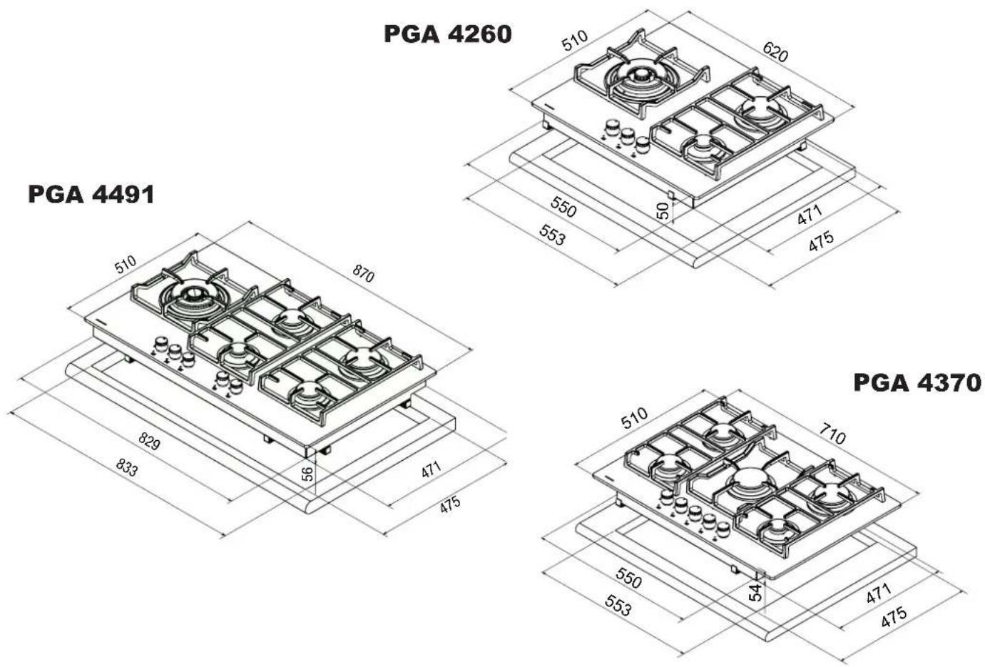
| Model | A B C D E F | ||||
PGA-4260 | 553 473 63.5 | 63.5 173.5 | min | 70 min | |
PGA-4370 | 553 473 63.5 | 63.5 175.5 | min | 70 min | |
PGA-4404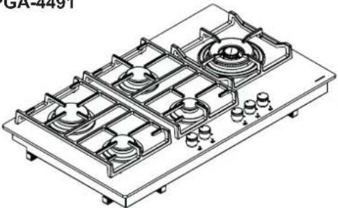 | 833 475 62.5 | 62.5 73.5 | min | 70 min |
* Mesurements in mm

Plate Fixing
The plate is equipped with a special gasket to prevent any infiltration of liquid into the cabinet. To install this gasket correctly, it is advisable to carefully follow the instructions below:
-
Remove all moving parts from the plate.
-
Take the insulating sealing strips carefully, carefully remove the transparent plastic covering the adhesive part of the strip. Then turn the gas plate upside down and stick the "E" strip correctly, following the outer edge of the gas plate all the way around the perimeter. Make sure that the ends of the strips match without overlapping.
Apply the adhesive strip evenly and securely to the plate, pressing with your fingers.
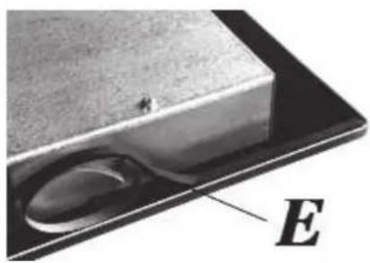
natural_image
Close-up of a metallic object with a curved indentation and a labeled point E (no text or symbols on the object itself)- Position the hotplate in the hole in the cabinet and fix it with the screws "F" of the fixing hooks "G".

- To prevent accidental contact with the surface of the top frame, which may become hot during operation, a wooden spacer must be screwed in place at a minimum distance of 70 mm from the edge.

Caution:
Do not allow the glass edge (A) to rest on the worktop or work surface alone, it must be the metal edge (B) that rests on it, which must be in contact with the worktop It is important to respect the fitting dimensions.

natural_image
Close-up of a metallic panel with labeled components A and B, showing internal structure and mounting points (no text or symbols beyond labels)IMPORTANT installation instructions
Important:
For perfect installation, adjustment or conversion of the hob for use with other gases, it is necessary to use a QUALIFIED INSTALLER: failure to comply with this standard will invalidate the guarantee.
The side walls must not extend beyond the height of the hotplate. The rear wall and surfaces adjacent to and around the hob must be able to withstand a temperature of 90 °C. The glue joining the plastic foil to the cabinet must be able to withstand a temperature of 150 °C to prevent the coating from peeling off. The equipment has to be installed in accordance with the requirements of the standards. This equipment is not connected to an exhaust system for combustion products; therefore, it must be installed in accordance with the above-mentioned standards. The applicable ventilation and ventilation provisions described below must be carefully observed.
Ventilation Of Premises
To ensure the correct operation of the appliance, it is essential that the room in which it is installed is permanently ventilated. The quantity of air required is that necessary for normal gas combustion and for ventilation of the room, the volume of which may not be less than 20 m3. The natural flow of air must take place directly through permanent openings in the walls of the room to be ventilated. These openings must face outwards and have a minimum cross-section of 100 cm2*.

CAUTION: If the hob burners are not fitted with a safety thermocouple, the ventilation opening must have a minimum cross-section of 200 cm2.
They must be carried out in such a way that they cannot be obstructed.
Indirect ventilation by means of exhaust air extraction from rooms adjacent to the room to be ventilated is also permitted, provided that the provisions of the rules in force are scrupulously respected.
Location and Aeration
Gas cooking appliances must always discharge combustion products through exhaust hoods connected to chimneys, flues or directly to the outside.
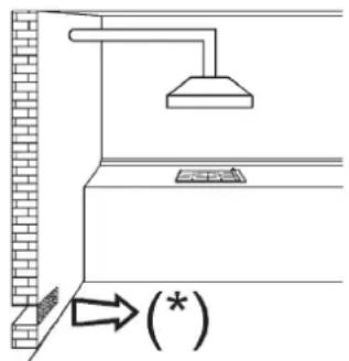
If it is not possible to install an extraction hood, a fan can be used by applying it to a window or to a wall with an outlet to the outside.
The fan shall be operated simultaneously with the equipment * , provided that the ventilation provisions of the standards are strictly observed.

Gas Connection
Before connecting the appliance, make sure that the data on the label on the underside of the hob are compatible with the distribution network. A label on the underside of the product and a label on the underside of the hob indicate the conditions for regulating the appliance: type of gas and operating pressure. When the gas is distributed through pipes, the appliance must be connected to the gas supply system:
- With a rigid metallic steel pipe, in accordance with the standard in force, the connections of which must be made with threaded fittings in accordance with EN 10226.
- With a copper pipe, conforming to the standard to be respected, the connections of which must be made with mechanically tight fittings, conforming to the standard in force.
- With a continuous-wall stainless steel hose in accordance with the standard, with a maximum length of 2 metres, and a standard-compliant stainless steel gasket. This pipe must be installed in such a way that it does not come into contact with moving parts of the built-in module (e.g. drawers) and must not pass through spaces that can be filled.

When gas is supplied directly from a cylinder, the equipment, supplied with a pressure regulator in accordance with the standard in force, must be connected:
- With a copper pipe, conforming to the emvigor standard, the connections of which must be made with mechanically tight fittings, conforming to the standard. - With a standard-compliant, continuous-wall stainless steel hose with a maximum length of 2 metres and a standard-compliant stainless steel gasket. This hose must be installed in such a way that it does not come into contact with moving parts of the built-in module (e.g. drawers) and must not pass through spaces that can be filled. It is advisable to use the special adaptor, which can be easily found in any specialised shop, on the hose to facilitate the connection with the pressure regulator connection mounted on the cylinder.
After making the connection, check for leaks by applying a soapy solution. Do not use flames.
Warning:
Please note that the gas inlet fitting of the appliance has a 1/2" threaded gas conical thread in accordance with EN 10226.
Important:
The device complies with the provisions of the sub-regulations for European Directives:
- Regulation (EU) 2016/426.
Warning:
This appliance can be used by children aged from 8 years and above and persons with reduced physical, sensory or mental capabilities or lack of experience and knowledge if they have been given supervision or instruction concerning use of the appliance in a safe way and understand the hazards involved. Children shall not play with the appliance. Cleaning and user maintenance shall not be made by children without supervision.
Electrical Connection
The electrical connection must be carried out in accordance with the applicable regulations and legal provisions.
Important:
Installation must be carried out in accordance with the manufacturer's instructions. Incorrect installation may cause damage to persons, animals or property for which the manufacturer cannot be held liable.
Before making the connection, check that:
- The electrical voltage of the appliance and the power supply must be suitable for the maximum power of the appliance (see label on the underside of the product).
- See the labels affixed to the underside of the product, indicating the power supply voltage and power characteristics, to use the appropriate section of electrical connection cables.
- The socket outlet or the device must be properly earthed in accordance with the currently valid regulations and legal provisions. No liability is accepted for non-compliance with these regulations.
When the connection to the mains power supply is made via the mains socket.
Connect the cables according to the wiring diagram, making sure that they correspond to the following indications:
- Connect a plug suitable for the load indicated on the label to the power supply cable "C", if it does not have one.
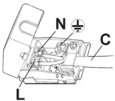
Letter L (phase) = brown wire; Letter N (neutral) = blue wire;
Symbol earth = green-yellow cable.
- The power supply cable must be laid in such a way that it can never reach a temperature of 90 °C at any point.
- Do not use any reducers, adapters or disconnections for the connection, as these can cause false contacts, which in turn can lead to dangerous overheating.
- After installation, the socket must be easily accessible.
When the connection is made directly to the mains:
- A single-pole circuit breaker with a minimum contact gap of 3 mm, suitably sized for the load of the appliance, must be fitted between the appliance and the mains supply.
- Remember that the earth wire must not be interrupted by the switch.
• Alternatively, the electrical connection can be protected with a high-sensitivity residual current circuit breaker.
It is strongly recommended to fix the green-yellow earth wire to an efficient grounding system.
Before carrying out any work on the electrical part of the appliance, the mains connection must be disconnected completely.
If the installation requires electrical modifications or if there is an incompatibility between the plug and the socket of the appliance, the plug must be replaced by a qualified and authorised person. The professional must check, in particular, that the cable cross-section of the plug is suitable for the power absorbed by the appliance.
WARNINGS:
All our products are in conformity with the European Standards and the corresponding amendments. Therefore the product conforms to the requirements of the European Directives in force concerning:
• Electromagnetic compatibility (EMC);
• Electrical safety (LVD);
- Restriction on the use of certain dangerous substances (RoHS);
- EcoDesign (ERP)
Before making any adjustments, the equipment must be switched off.
After completion of the regulations or pre-regulations, the seals must be restored by a technician.
Primary air regulation in our burners is not necessary.
Faucet Regulation
Regulation of the "Minimum".
- Turn the burner on and set the knob to the "Minimum" position.

- Remove the knob "M" from the tap which is attached to pressure on the rod.
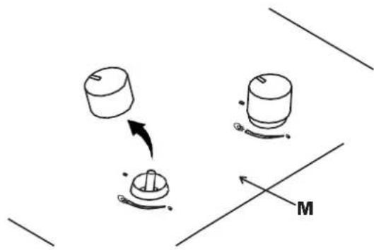
- The by-pass for minimum flow adjustment can be: On the side of the tap or on the inside of the bar. In either case, the adjustment is made by inserting a small screwdriver "D" into the side of the tap, or into the hole "C" inside the gas tap.

- Turn to the right or left to bypass correctly the flame adjustment to the limited range position.
These adjustment instructions apply only to burners operating at G20, while for burners operating at G30 or G31 the screw must be screwed in completely (clockwise).
LUBRICATION OF THE KEYS. If a tap is blocked, do not force it and ask for technical assistance.
CLEANING
ATTENTION:
Before each cleaning operation, disconnect the appliance from the gas supply and the electrical supply.
Worktop
If the surface of the hob is to be kept shiny, it is very important to wash it after use with warm soapy water, rinse and dry it. Likewise, the enameled grates, enameled covers "A", "B" and "C" and the burner heads should be washed and the spark plugs "AC" and thermocouple sensors "TC" should be cleaned. These components must not be washed in the dishwasher. Clean gently with a small nylon brush as shown and allow to dry thoroughly. Cleaning should be carried out with the board and its components cold, without the use of metallic sponges, abrasive powders or corrosive sprays.
Do not allow your surfaces to remain in contact with products such as vinegar, coffee, le-che, saline water or lemon or tomato juice.
WARNINGS:
When reassembling the components, it is advisable to observe the following recommendations:
- Check that the cracks in the "T" burner heads are not obstructed by foreign bodies.
- Make sure that the enamelled caps "A", "B" and "C" are correctly positioned on the burner head. This is verified when the cover placed on the head is perfectly stable.
- The louvres must be placed on the appropriate centring pins (or on the aluminium profile). Check for perfect stability.
- If it is difficult to open and close a key, do not force it: call for technical assistance as soon as possible.
- Do not use steam jets to clean the appliance.
- To prevent possible ignition problems, periodically carry out a thorough cleaning of the spark plugs (ceramic and electrode) and thermocouples.


natural_image
Line drawing of a hand using a tool to clean or inspect a circular component (no text or symbols)Note: Continued use may cause the burner area to take on a different colour from the original due to the high temperature.
Ceramic hob
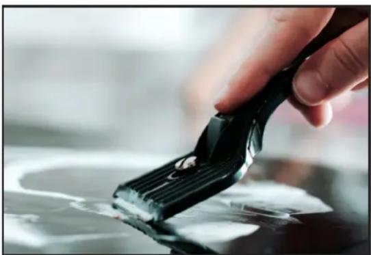
To keep the glass ceramic surface shiny, it is advisable to treat the glass surface before use with a silicon-based product to form a protective film against water and dirt. This protective film is not durable, so it is advisable to reapply the product frequently. Always clean the surface after use when the glass is still warm. Do not use metallic sponges, abrasives or corrosive sprays for cleaning. Depending on the degree of soiling, the following should be remembered:
- For light stains it is sufficient to use a damp sponge.
- Stubborn, encrusted dirt is easily removed with a scraper, not included with the hob, which is readily available on the local market. Use with care as this may cause injury.
- Remains of liquids spilled from pans are removed with vinegar or lemon.
- Be careful not to drop sugar or sugary foods on the hob during cooking. If this happens, turn off the hob and immediately clean the still hot handles using hot water and a scraper.
- If the hob is not cleaned properly or the pans are handled incorrectly, colours, metallic streaks or scratches may appear over time. Although these scratches are difficult to remove, they do not affect the proper functioning of the cooktop.
- Do not use steam jets to clean the appliance.
natural_image
Close-up of a hand holding a black plastic clip with a small droplet on a reflective surface (no text or symbols visible)MAINTENANCE
Replacement Of Injectors.
The burners can be adapted to different types of gas by fitting the nozzles corresponding to the gas available. To do this, remove the burner heads and, using a straight spanner, unscrew the injectors and replace them with an injector compatible with the gas available. It is advisable to block the injector forcefully.

After having carried out the replacements, the technician must adjust the burners as described in the previous section, seal any adjustment or pre-adjustment orifices and apply the label corresponding to the new gas adjustment carried out on the appliance, replacing the previous one. This label can be found in the bag of the replacement injectors.
The bag containing the injectors and labels is supplied with the appliance. It can also be ordered from an authorised service centre. For the installer's convenience, a table with the capacities, the thermal capacities of the burners, the diameter of the injectors and the pressure exerted by certain gases is provided below.
Burner Arrangement


| BURNERS THERMAL | GAS EXERCISE PRESSURE mbar | CAPACITY | ∅ NOZZLE 1/100 mm | 100HEAT CAPACITY (W) | ||||
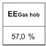
| NO. | DENOMINATION | gr/h l/h | Min. Max. EEgasBurners | |||||
| 1 | ULTRARAPID | G30 - BUTANE G31 - PROPANE G20 - NATURAL | 28 - 30 37 20 | 291 286 | 381 | 100 B 100 B 145 A | 1800 1800 1800 | 4000 4000 400 |
| 2 | FAST | G30 - BUTANE G31 - PROPANE G20 - NATURAL | 28 - 30 37 20 | 203 200 | 267 | 83 83 117 Y | 900 900 900 | 2800 2800 2800 |
| 3 | SEMI-APID REDUCED | G30 - BUTANE G31 - PROPANE G20 - NATURAL | 28 - 30 37 20 | 102 100 | 133 | 58 58 85 Y | 550 550 550 | 1400 1400 1400 |
| 4 | SEMI-FAST | G30 - BUTANE G31 - PROPANE G20 - NATURAL | 28 - 30 37 20 | 127 125 | 167 | 68 68 98 Z | 550 550 550 | 1750 1750 1750 |
| 5 | ASSISTANT | G30 - BUTANE G31 - PROPANE G20 - NATURAL | 28 - 30 37 20 | 73 71 | 95 | 51 51 75 X | 450 450 450 | 1000 1000 1000 |
Types And Sections Of Power Cables
| TYPE OF PLATE | CABLE TYPE | SINGLE-PHASE POWER SUPPLY |
| Gas hob H05 | RR - F Cross | section 3x 0.75 mm^2 |
ATTENTION!!!
If the power cable is replaced, the installer must have the earth conductor (B) longer than the phase conductors and must also observe the warnings given in the "Electrical Connection" section

natural_image
Simple line drawing of a curved pipe or tube with a base and a labeled point B (no text or symbols)WARNINGS:
- Maintenance must only be carried out by authorised personnel.
- In case of cable failure or breakage, remove the cable and do not touch it. Furthermore, you should unplug the device and do not switch it on. Call the nearest authorised service centre to solve the problem.
In case of adaptation of the cooker to another type of gas, operate as described in the instructions for installation and use and replace the label on the bottom with the one supplied in the spare parts bag
REPORTED TECHNICAL DATA FROM THE LABEL
3 FIRES (60) UR LEFT
CATEGORY = II2H3+
G 30 - BUTANE = 28 - 30 mbar G
31 - PROPANE = 37 mbar
G 20 - NATURAL = 20 mbar
Qn Natural Gas = 7.80 kW
Qn GPL = 567 g/h (G30)
557 g/h (G31)
VOLTAGE = 220 - 240 V\~
FREQUENCY = 50/60 Hz
5 FIREWORKS (70)
CATEGORY = II2H3+
G 30 - BUTANE = 28 - 30 mbar G
31 - PROPANE = 37 mbar
G 20 - NATURAL = 20 mbar
Qn Natural Gas = 10.95 kW
Qn GPL = 796 g/h (G30)
782 gr/h (G31)
VOLTAGE = 220 - 240 V\~
FREQUENCY = 50/60 Hz
5 FIRES (91) UR LEFT
CATEGORY = II2H3+
G 30 - BUTANE = 28-30 mbar
G 31 - PROPANE = 30-37 mbar
G 20 - NATURAL = 20 mbar
Qn Natural Gas = 10.95 kW
Qn GPL = 796 g/h (G30)
782 gr/h (G31)
VOLTAGE = 220 - 240 V\~
FREQUENCY = 50/60 Hz
PRODUCT WARRANTY
INOXPAN S.L., thanks you for choosing and placing your trust in a product of our brand Pando, which is distinguished by its Quality, Design and Innovation, being faithful to its origins and commitments.
PANDO WARRANTY CONDITIONS
This appliance is guaranteed for 3 years from the date of purchase and covers it against any manufacturing defect that may affect its proper operation. For the validity of the warranty to be valid, it is essential to present the invoice or purchase receipt to the Pando Authorised Service technician.
During this period, the Company undertakes to replace or repair free of charge any defective part due to a defect or manufacturing defect in the appliance, until it is in proper working order, as well as the necessary labour and expenses incurred as a result of such repair or replacement.
EXCLUSIONS FROM THE PANDO WARRANTY:
It will not be covered by the product warranty and could be cause for cancellation of this, and in these cases the user will be responsible for the costs of materials, labour and travel of the technical service, in the following cases:
- If the installation of the product has not been carried out by Authorised Professional Specialists, Lamp fitters or Electricians, or by Pando Technical Service personnel, who meet the requirements of safety standards and gas and electricity regulations.
- Breakdowns or damage caused by transport or transfer, manipulation of the device by unauthorised personnel not authorised by this company or the Pando brand.
- Faults or malfunctions caused by failure to observe or follow the safety, operating and maintenance instructions in the product manual.
- Breakdowns or problems caused by not having the required free spaces in the furniture, as indicated in the installation manual, for adequate ventilation of the product.
- The installation does not have the mandatory and standardised safety elements for power disconnection.
- The technician does not have easy access to the product, because there are elements that prevent easy and safe access. The means required for the authorised Pando technician to access the device are the responsibility of the user.
- The product does not have the appropriate product label or nameplate for the type of gas connected.
- The installation of the product, nor the modification of gas type (change of injectors).
- Carrying out inspections or commissioning, cleaning or maintenance of the product.
- When the product is intended for commercial or non-domestic use, for which it is not intended.
- Aesthetic components of wear and tear, all burner accessories, grills, controls, nozzles.
- Rust, burns, stains or discolouration of the product and accessories caused by improper maintenance or use, or by improper application or unprotected exposure to corrosive elements such as cleaning agents not recommended by the manufacturer and unsuitable cleaning agents.
- Blows, deformations, dents, scratches, scuffs, breakages on the body, glass or accessory elements of the product.
- Presence of foreign bodies foreign to the device, inside or outside the product.
- Breakdowns or damage caused by variations in the electricity supply or fortuitous and natural causes of atmospheric or geological origin such as storms, lightning, earthquakes, floods, etc.
- Appliances from resale, second hand, trade-in or exhibitions that are more than three years old from the date of manufacture.
INOXPAN, S.L., is expressly excluded from any liability for any direct or indirect damage to persons or materials caused by improper handling of the device.
Contact details Offi cial Authorised Pando Technical Service:
| ESPAÑA, PORTUGAL Y ANDORRA OTROS | PAÍSES | ||
| www.pando.es/asistencia-tecnica/ |  | www.pando.es/en/after-sales-services/ |  |
Pol. Ind. El Cros
SERVICIO POST VENTA España, Portugal y Andorra

Environmental Management System Certification
UNE-EN ISO 14001:2015
ES20/208675


- Pando integralcooking
- The Global Kitchen Partner
- DEL MEDIOAMBIENTE Y TRATAMIENTO DEL RESIDUO
- USO DEL PRODUCTO....12
- CONSEJOS PARA AHORRAR ENERGÍA Y CUIDADO DE RECIPIENTES....14
- PROBLEMAS COMUNES Y SOLUCIONES....15
- INSTALACIÓN ....16
- Conexión Del Gas
- MANTENIMIENTO
- ADVERTENCIAS:
- Ligação De Gás
- MANUTENÇÃO
- ADVERTÊNCIAS:
- PROTECTION DE L'ENVIRONNEMENT ET TRAITEMENT DES DÉCHETS
- Instructions d'installation IMPORTANTES
- Important :
- Raccordement Au Gaz
- ENTRETIEN
- MISES EN GARDE :
- ENVIRONMENTAL PROTECTION
- ENVIRONMENTAL PROTECTION AND WASTE TREATMENT
- INDEX
- SAFETY INSTRUCTIONS 86
- DESCRIPTION OF THE HOB....89
- USE OF THE PRODUCT 90
- ENERGY SAVING TIPS AND CONTAINER CARE....92
- COMMON PROBLEMS AND SOLUTIONS....93
- INSTALLATION....94
- CLEANING....101
- MAINTENANCE....102
- Please Note That...
- SAFETY INSTRUCTIONS
- DESCRIPTION OF THE HOB
- USE OF THE PRODUCT
- Burners
- • Automatic electric ignition
- - Ignition of burners fitted with safety thermocouples
- How to use the burners
- WARNINGS AND ADVICE TO THE USER
- Attention
- ENERGY SAVING TIPS AND CONTAINER CARE
- INSTALLATION
- TECHNICAL DATA FOR INSTALLERS
- Plate Insertion
- Fitting dimensions
- Plate Fixing
- Caution:
- IMPORTANT installation instructions
- Important:
- Ventilation Of Premises
- Location and Aeration
- Gas Connection
- Warning:
- Electrical Connection
- Before making the connection, check that:
- When the connection to the mains power supply is made via the mains socket.
- When the connection is made directly to the mains:
- WARNINGS:
- Faucet Regulation
- CLEANING
- ATTENTION:
- Worktop
- Ceramic hob
- MAINTENANCE
- Replacement Of Injectors.
- Burner Arrangement
- Types And Sections Of Power Cables
- ATTENTION!!!
- REPORTED TECHNICAL DATA FROM THE LABEL
- FIRES (60) UR LEFT
- FIREWORKS (70)
- FIRES (91) UR LEFT
- PRODUCT WARRANTY
- PANDO WARRANTY CONDITIONS
- EXCLUSIONS FROM THE PANDO WARRANTY:
Brand : Pando
Model : PGA4370
Category : Cooker