
PGA4490 - Cooker Pando - Free user manual and instructions
Find the device manual for free PGA4490 Pando in PDF.
| Brand | Pando |
| Model | PGA4490 |
| Product type | Built-in gas hob |
| Number of burners | 5 (triple ring, rapid, semi-rapid reduced, semi-rapid, auxiliary) |
| Total power (gas) | 10.7 kW (NG) / 10.7 kW (LPG) |
| Dimensions (W x D x H) | 860 x 510 x 80 mm (approx.) |
| Weight | Approximately 22 kg |
| Power supply | 220-240 V ~ 50/60 Hz |
| Gas type | NG (G20) 20 mbar / LPG (G30/G31) 28-30/37 mbar |
| Surface material | Glass ceramic |
| Controls | Electronic touch panel with 7-segment display |
| Main functions | Electronic ignition, flame adjustment (7 levels), independent timer per burner, child safety lock, automatic shut-off (4h max) |
| Safety | Thermocouple, safety lock, manual unlock, self-diagnosis with error codes |
| Care and cleaning | Clean burners and grates after each use, avoid abrasive products, do not wash in dishwasher |
| Spare parts and repairability | Replacement nozzles for different gases, parts available from Pando authorized centers |
| General information | Household appliance, installation by qualified professional, 2-year warranty |
Frequently Asked Questions - PGA4490 Pando
User questions about PGA4490 Pando
0 question about this device. Answer the ones you know or ask your own.
Ask a new question about this device
Download the instructions for your Cooker in PDF format for free! Find your manual PGA4490 - Pando and take your electronic device back in hand. On this page are published all the documents necessary for the use of your device. PGA4490 by Pando.
USER MANUAL PGA4490 Pando
ΣQn LPG Gas = 10.7 kW
QnLPGas = 778g / h (G30)
764 g/h (G31)
INDICACOsParaA INSTALACAO
10) REMPLACEMENT DES BUSES
We sincerely thank you for purchasing our product.
We are sure that this new appliance, state-of-the-art, practical and functional, manufactured of the highest quality materials, will fully meet your expectations. The appliance is very simple to operate.
However, to ensure optimum results when using it, please read and understand this manual.
Provided instructions are valid only in the countries whose symbols are shown on the operating manual title page and on the appliance label.
The manufacturer accepts no liability for potential personal harm or property damage resulting from incorrect installation or improper use of the appliance.
Pando
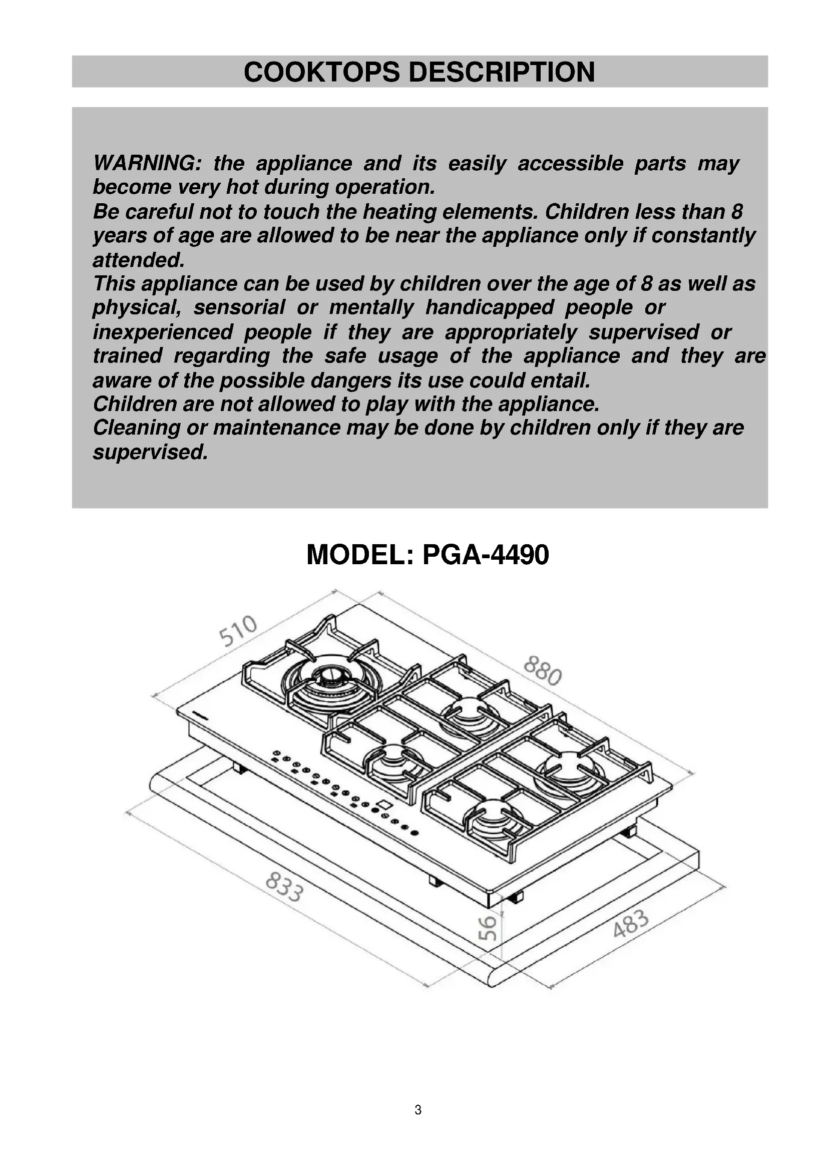
MODEL:PGA-4490
The manufacturing company accepts no liability for discrepancies in the manual that may arise as a result of misprints or copying errors. Figures in the text are given for reference only. The manufacturer reserves the right to make modifications of its products that are required or necessary for meeting user needs in the opinion of the manufacturer, but that do not affect basic safety and operating specifications of the appliance. This cooktop is designed to be used exclusively as food preparation equipment. Using it for other purposes (such as room heating) is improper and dangerous.
WARNING: the appliance and its easily accessible parts may become very hot during operation.
Be careful not to touch the heating elements. Children less than 8 years of age are allowed to be near the appliance only if constantly attended.
This appliance can be used by children over the age of 8 as well as physical, sensorial or mentally handicapped people or inexperienced people if they are appropriately supervised or trained regarding the safe usage of the appliance and they are aware of the possible dangers its use could entail.
Children are not allowed to play with the appliance.
Cleaning or maintenance may be done by children only if they are supervised.

MODEL: PGA-4490
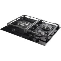
COOKTOPS DESCRIPTION

MODEL:PGA-4490
1 Triple flame burner 3750 ÷ 3800 W
2 High speed burner 2800 W
3 Normal speed burner, small size 1400 W
4 Normal speed burner 1750 W
5 Auxiliary burner 1000 W
6 Grade 1F
7 Grade 2F
8 Touch controls
The cooktop is equipped with an electronic burner monitoring and control system using a touch panel.
Attention: this appliance is designed for domestic use in a home environment by normal consumers. The appliance may be used only by adult, completely sane persons. It is prohibited to let children approach the appliance or play with it. Easily accessible parts on the appliance front may become very hot during use.
Make sure that children and handicapped persons do not touch hot surfaces and keep away from the appliance during its operation.
COOKTOPS DESCRIPTION

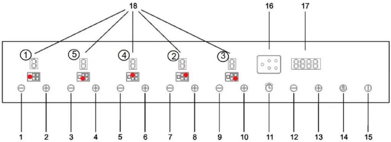
5 BURNERS 90 cm
1-Burner 1"-” button
2-Burner1“+”button
3-Burner5“-”button
4-Burner5 ^ 喜 + ^ 喜 button
5-Burner4“-”button
6-Burner4“+”button
7-Burner2"-”button
8-Burner2“+”button
9-Burner3“-”button
10-Burner3“ ^+ ”button
11 - Clock button
12 - Clock programming “-” button
13 - Clock programming "+" button
14 - Safety lock button
15 - ON/OFF button
16 - Operating burner position indicator
17 - Timer display
18 - Power level display (0 - 7)
This cooktop is designed to be used exclusively as food preparation equipment. Using it for other purposes (such as room heating) is improper and dangerous.
Attention: working areas become very hot during operation: keep away from children!
FUNCTIONS available for user/technician:
- Standby mode (burners off, control panel on).
Control panel lock to protect from accidental ignition. - Power setting for each burner on 7 levels.
- Safety lock with manual reset to release the lock initiated from the control panel.
- Adjustment of each burner minimum power level (can be performed by a technician only).
- Programming for the type of used fuel: methane / liquefied petroleum gas (can be performed by a technician only).
- Switch-off time programming for each burner.
Maximum time for each programmed burner stored in FLASH memory is 4 hours. - Temperature measurement by an electronic board.
- Elimination of faults/failures using codes indicated on the display.
OPERATION
1) BURNERS
There are marks on the cooktop surface indicating the burner controlled by each knob. After connecting gas using the main control panel or opening the gas canister valve, ignite burners following the steps described below.
Switching on the cooktop
To switch on the cooktop, press the ON/OFF button and hold for at least 2 seconds. The cooktop will switch on. Burner displays indicate a zero level, which corresponds to the switched-off state of burners.
Burner ignition
To ignite a burner, press and hold the "+" button corresponding to the burner you want to ignite. You can press the "+" button one more time within 4 seconds to ignite the burner on level 7. After that the control system will make 3 attempts max with 10 second intervals.
If the burner does not ignite after the third attempt, it will be locked, and the letter "b" will be shown on the corresponding display. To unlock a burner, perform the steps described below.
Each burner that is not programmed with the corresponding timer will be automatically switched off after 4 hours of continuous operation.
Each burner operation is indicated by the corresponding figure indicating flame level during burner combustion.
Setting burner flame level
When a burner is on, to increase its power level press the "+" button, and to decrease the power level press the "-" button. To change the power level successively, press and hold the "+" or "-" button and release it when the required level is reached. Power level changes from 1 to 7.
Switching off the burner
To switch off a burner, simultaneously press the corresponding "+" and "-" buttons for one second or set level 0 for the burner using the "-" button. If the cooktop is off, the letter "H" (hot) will be flashing on the corresponding display for a few seconds. If the cooktop is not off, the flashing symbol "H/0" indicates that the burner is hot. The time for which the flashing symbol is displayed is given as a reference. It can vary dramatically depending on operation conditions.
Switching off all cooktop burners
To switch off all burners simultaneously, briefly press the "ON/OFF" button. The cooktop will switch off.
Burner switch-off time programming
Attention: the user must be always present during cooktop operation.
For each burner a time can be programmed after which it will automatically switch off.
To program the burner timer: switch the cooktop on using the "ON/OFF" button. Ignite the burner you want to program using the "+" button, choose the flame level required using "+" or "-" buttons and press the clock button (11) several times to select the burner you want to program. Timer display will indicate 0.00.
The number to the left of the point indicates hours, the number on the right indicated minutes. When buttons 12 and 13 are pressed ("- " and "+" in clock programming), the display will start flashing. This means you can increase or decrease the number of operation hours or minutes between 0 and 4 hours. When programming is finished, the display will stop flashing and indicate the set time. The corresponding LED will light up. No confirmation is required.
During programming you can reset the input value at any time by simultaneously pressing button 12 and 13 ("- " and "+" in clock programming). If the time is set to zero, burner timer is switched off.
OPERATION
You can return to timer programming mode by pressing the time button (11) to check the time remaining until switch-off or to change the current settings.
The timer can be programmed only with the burner in operation. Countdown starts immediately after burner ignition. When the countdown is over, the programmed burner will go out and give a series of sound signals for 30 seconds (you can turn the sound signals off by pressing the clock button (11)).
If the programmed burner is put out by user, the corresponding timer is switched off.
Programming simultaneous switch-off time for several burners
You can program switch-off time for several burners that operate simultaneously. The initial step is identical to the above-mentioned single burner programming. To complete programming operation: press the clock button (11) and move on to the next burner (no confirmation of programmed data is required). If another burner needs to be programmed, you must confirm it by pressing the clock button.
Clock adjustment
In case of power supply failure, you must set the time displayed by the cooktop internal clock. To set the clock, switch on the cooktop by pressing the "ON/OFF" button. Then simultaneously press buttons 14 and 11 and hold them for at least 3 seconds.
The flashing number to the left of the point indicates hours, the number on the right indicates minutes. You can increase or decrease hours value by pressing buttons 12 and 13. If you press and hold buttons 12 and 13, you can change the hours value successively.
To set minutes, press the clock button (11) one more time. Numbers to the right of the point will start flashing.
You can set the minutes value in the same way as the hours value.
To save the set time, press the clock button (11).
Releasing burner lock (Fig. 14)
If a burner is locked, letter "b" will be indicated on the corresponding display. To release the lock, simultaneously press buttons 1 and 14 (for 90~cm ) or buttons 3 and 14 (for 60~cm ) and hold them for at least 2 seconds. After the lock is released, burners are set to level 0 and are ready to be switched on.
NOTE: if the lock release process is repeated 5 times within 15 minutes, the appliance will indicate signal
FLT06 and will not accept lock release commands for the next 15 minutes.
Child lock function
Can be activated only if the cooktop is off. To activate, press button 14 and hold it for at least 3 seconds. After the key lock is activated, all keys are turned off. In this case decimal points are indicated on each burner power level display.
To deactivate this function, press button 14 one more time and hold it for at least 3 seconds (all decimal points on power level displays will go out when the key lock is released).
Key lock release
To release key lock, press button 14 and hold it for at least 2 seconds. All decimal points on flame level displays will disappear when key lock is released.

RELEASING BURNER LOCK "b"
FIG. 14
OPERATION
| Burners | Power, W | Ø of pan, cm |
| Triple flame | 3750 ÷ 3800 | 24 ÷ 26 |
| High speed | 2800 | 20 ÷ 22 |
| Normal speed | 1750 | 16 ÷ 18 |
| Normal speed small size | 1400 | 16 ÷ 18 |
| Auxiliary | 1000 | 10 ÷ 14 |
- If the cooktop is equipped with a cover, before opening, remove all food residues that may have spilled on its surface. If the appliance is equipped with a glass cover, there is a risk that it explodes if heated. Before closing the cover put out all burners and leave them to cool.
- Position pans in such a way that they do not protrude over the cooktop limits.
WARNING:
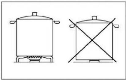
- Igniting burners equipped with control thermocouple is possible only when the control knob is in the "maximum" position (high flame, Fig. 1).
- Do not leave the appliance unattended with the burners in operation. Make sure there are no children near the appliance. Among other things, make sure that pot handles are in the correct position. During cooking keep an eye on using oils and fats, as they are easily flammable.
- Using sprays near working appliance is prohibited.
OPERATION
WARNING AND USER TIPS:
- Operation of cooking gas appliances results in generating heat and moisture in the room where they are installed. Therefore, adequate ventilation of the room must be provided. Make sure that openings for natural ventilation remain unobstructed (Fig. 1) and switch on the mechanical ventilation device (extractor hood or electric fan, Fig. 2 and Fig. 3).
- If the appliance is operated intensively or for a long period of time, additional ventilation may be required. For example, you may have to open a window or improve ventilation efficiency by increasing the power of available mechanical ventilation.
- If the equipment is used for a long time and intensively, additional airing may be required. In this case you have to open a window or improve airing by increasing mechanical ventilation power, if installed.
- Do not attempt modifying appliance technical specifications: it may be dangerous.
- If you decide to stop using this appliance (or replace an outdated model), before disposing, it is recommended to make the appliance unfit for use, following all applicable regulations for health and environment pollution protection foreseen for such cases. Dismantle parts that can be dangerous, especially for children, who may use the disposed appliance as a toy.
- Do not touch the appliance if your hands or feet are moist or wet.
- Use the appliance only after you put on your footwear.
- The manufacturer cannot be held liable for damage that may arise as a result of improper, faulty or incorrect operation.
- During operation and immediately after it is over, some cooktop parts become very hot: do not touch.
- After cooktop operation make sure that rotating control knobs are in the "off" position. Shut the main gas supply system valve or canister valve.
- If there is a malfunction of gas supply valves, contact technical assistance service.
ATTENTION:
If the cooktop glass is damaged:
- immediately put out all burners and switch off electrical heating elements, then disconnect the appliance from electrical mains,
- do not touch the appliance surface,
do not use the appliance.
Attention: working areas become very hot during operation: keep away from children!

(*) AIR INLET: SEE CHAPTER ON INSTALLATION (SECTIONS 5 AND 6)
FIG. 1
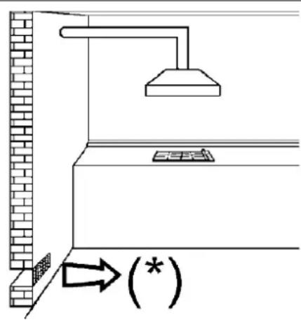
FIG. 2

FIG. 3
OPERATION
ENERGY AND COOKWARE SAVING TIPS
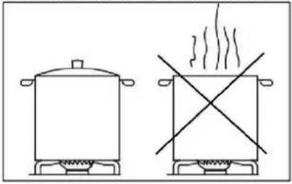
- To avoid energy loss, do not use pots without lids or with partially closed lids when cooking.
-
Position cookware precisely in the burner center.
-
Do not place large-sized cookware near control knobs. These can be damaged by excessively high temperature.
-
Never place cookware directly on the burner, but only on the grate. Before that, make sure that grates are installed correctly.
- Be careful when handling cookware on the cooktop. Avoid shocks and do not place objects that are too heavy.

- Do not remove cookware when the flame is still burning. This may result in heavy injuries.

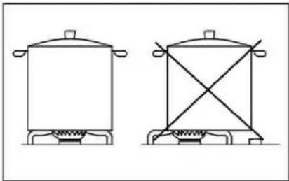
- Use cookware with the size appropriate for each burner. Do not use cookware with the size that is smaller than burner size. Flame should not be touching cookware sides.

- Use only cookware with good, flat and thick bottom. Deformed cookware can overturn.

CLEANING
ATTENTION: Before attempting any cleaning work disconnect the appliance from gas mains and electrical mains.
2) WORKTOP
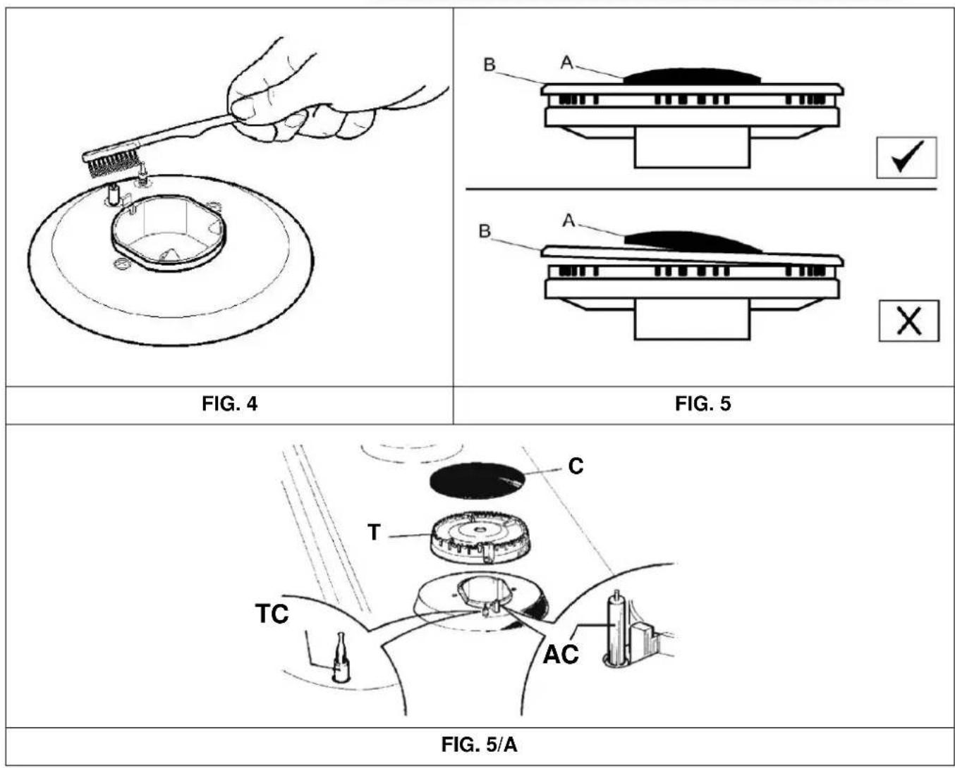
To keep the glass surface shiny, wash it using warm water with soap after each use, rinse and dry. You should also wash enameled grates, enameled caps A B and C and burner heads (see Fig. 5-5/A), clear igniters AC and thermocouple sensors TC (see Fig. 5/A). Washing all of these parts in a dishwasher is prohibited. Make sure to be careful when cleaning. Use a small nylon brush as shown in the figure (see Fig. 4) and leave the appliance until completely dry.
Cleaning should be done after the cooktop and its components cools down completely. It is prohibited to use scouring pads, abrasive powders and corrosive sprays.
Long-time contact of the surface with such products as vinegar, coffee, milk, salty water and lemon or tomato juice, must be avoided.
Note: in case of regular use, the area of burner installation can discolor due to exposure to high temperature.
CLEANING
CERAMIC GLASS
To maintain the shine of a glass ceramic surface, it is recommended to apply a silicon-based agent on the glass surface before starting use. This will create a film protecting from water and contamination. The protective film is not durable; therefore, you should repeat treatment with this substance frequently. It is very important to clean the glass after use while it is still warm. Do not use scouring pads, abrasive products and corrosive sprays for cleaning.
Depending on contamination severity, one should note the following:
- Small stains can be removed using a soft sponge.
- Residues of liquids spilled out of pans should be removed using vinegar or lemon.
- Be careful not to let sugar or sugar-containing products end up on the cooktop during cooking. If this should happen, switch the cooktop off and immediately remove the stains before they cool down, using warm water and a moistened sponge.
- Inadequate cooktop cleaning or incorrect cookware handling may eventually lead to color spots, metal glitter or streaks appearing on the cooktop. Although hard to remove, these streaks are not a symptom of cooktop malfunctioning.
- Using steam jet for appliance cleaning is prohibited
WARNING:
When installing cooktop components into place, please follow these guidelines:
- Make sure that the T slots of burner heads (Fig. 5/A) are not blocked by foreign objects.
- Make sure that enameled caps A, B and C (Fig. 5-5/A) are correctly installed on burner heads. In the correct position a cap installed on the head is completely stable.
- If a valve opens or closes with effort, do not apply force: contact the technical assistance service immediately.
- Grates must be installed using appropriate centering pins (or on aluminum profile, if available). Check for complete stability.
- Using steam jet for appliance cleaning is prohibited.
INSTALLATION
TECHNICAL INFORMATION FOR INSTALLATION PERSONNEL
Installation, adjustment, modification and maintenance described in this chapter can be performed only by qualified personnel.
The equipment must be correctly installed in compliance with valid regulations and manufacturer's requirements.
The manufacturer cannot be held liable for damage to people, animals or property resulting from incorrect installation of the appliance.
Modifications of devices that ensure equipment safety or automatic regulation can be made only by the manufacturer or its verified supplier throughout the entire service life.
INSTALLATION TIPS
- The appliance is designed to work continuously for not more than 24h (continuous operation system). When this time goes out, an adjustment break begins. During this break the appliance will check its performance efficiency.
- This automatic appliance is a safety-related device; its design modifications are prohibited. Modifications to this appliance design relieve the manufacture from any liability whatsoever and cancel the warranty.
-
The appliance conforms to all applicable national and European standards (such as EN 60335-1/EN 60335-2-102) in the field of electrical safety.
-
Before starting to use the cooktop, carefully check the cables: a non-conforming cable can damage the appliance and put the system safety at risk.
- Turn the cooktop on and off only after the power supply is connected.
- Do not let water droplets end up on the appliance.
- Make sure that valve cables are not located near the high voltage cables of ignition transformer.
- Before switching on make sure that there are no foreign objects on the cooktop, particularly, in the control panel area.
After the cooktop is turned on, wait for a few seconds for the process of control panel automatic calibration to be completed. - In case of "partial" short circuit or insufficient insulation between line and earthing, voltage on the sensor electrode may drop to a level when appliance interlock is initiated, because it is not possible to accept the ignition signal.
- Touching the extra-low voltage (ELV) circuit is dangerous (only basic insulation as per EN 60730-1 is provided). Therefore, the appliance must ensure a level of electrical discharge protection for the user interface that is equivalent to double insulation.
IMPORTANT: for correct cooktop installation, adjustment or modification for use with different types of gas, contact a QUALIFIED INSTALLER. Failure to meet this requirement results in warranty cancellation.
DIMENSIONS TO BE FOLLOWED (in mm from cut-out)
| A | B | C | D | E | F | |
| 5F (90) | 833 | 483 | 62.5 | 62.5 | 55 min | 70 min |
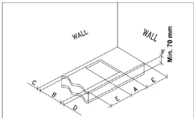
FIG.6

FIG.7
INSTALLATION
3) COOKTOP BUILDING
Remove external packaging and internal packagings of all movable components. Make sure that the cooktop is in good working condition. If there are doubts as far as appliance condition is concerned, using the appliance is prohibited. Please contact qualified personnel.
Keep packaging elements (cardboard, bags, foamed polystyrene, nails ...) away from children as they are a potential hazard source.
To build the cooktop in, cut out an opening in the load bearing furniture table top with the dimensions given in Fig.6. Make sure that you strictly follow the limit distances in the area of appliance installation (see Fig. 7).
The equipment is a class 3 product. Therefore, it must comply with all the requirements specified in standards applicable to this product.
The appliance may be installed only with one side wall (on the right or left of the cooktop). This wall must be higher than the cooktop level and must be positioned with respect to the minimum distance indicated in the table given below.
4) COOKTOP FIXING
The cooktop is fitted with a special gasket that prevents any ingress of liquid inside furniture. To correctly install this gasket, it is recommended to strictly follow the below instructions:
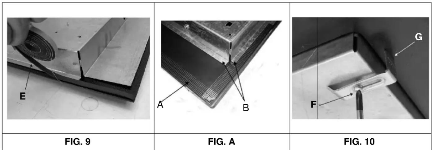
- Remove all movable parts of the cooktop. Cut the gasket into 4 parts of appropriate length in order to install them on 4 edges of the glass top.
- Turn the cooktop over, correctly position the adhesive surface of gasket E (Fig. 8) under the cooktop edge, so that the outside gasket edge is precisely aligned with the cooktop perimeter edge. Outside band edges must be aligned without overlapping.
Pressing with your fingers, attach the gasket to glass evenly and reliably.
- Install the cooktop into the opening made in the furniture and fix it using screws F, by means of fixing hooks G (see Fig. 9).
- To prevent potential accidental contact with cooktop surface that becomes very hot during operation, a wooden pad must be installed at the distance of at least 70~mm from the tabletop, and fixed using screws (Fig. 6).
- To fix this appliance on the load -bearing structure, we recommend to avoid using mechanical or electrical screwdrivers. Instead, tighten the fixing hooks by hand, with medium force.
Warning: the edge of glass section (A) must not rest on the panel or worktop. It should support the edge of metal section (B) that must be touching the cooktop (see Fig. A). It is important to take into account the cut-in dimensions.
INSTALLATION
IMPORTANT GUIDELINES TO BE FOLLOWED FOR INSTALLATION
The installer must note that side walls which might be installed, must not be higher than the cooktop level. Besides, the back wall and surfaces adjacent to and surrounding the cooktop, must withstand the temperature of 90^ .
Adhesive used for attaching the plastic plate to furniture must withstand the temperature of at least 150^ to prevent coating separation.
Provisions of applicable standards are to be followed during appliance installation.
This appliance is not fitted with a device for combustion products removal. Therefore, the appliance must be installed according to the installation requirements given above. Special attention must be given to the applicable guidelines with respect to ventilation and airing specified below.
5) ROOM VENTILATION
To ensure correct operation of appliance, continuous ventilation must be provided in the room of its installation. The amount of air required for normal gas combustion and room ventilation must be provided. This amount must not be less than 20m^3 . Natural inlet of air must be ensured directly through permanent openings made in walls of the room to be ventilated. These openings must be led outside and have a cross-section of at least 100cm^2 (see Fig. 1). They must be done in a way that eliminates the risk of their blockage.
It is also acceptable to provide indirect ventilation by supplying air from rooms adjacent to the room to be ventilated. Provisions of applicable guidelines must be strictly followed
6) LOCATION AND AIRING
It is necessary to ensure removal of combustion products from cooktops using extraction hoods that must be connected to vent stacks, chimneys or have an outlet directly to outside (see Fig. 2). If using a vent stack is not possible, and subject to scrupulously following ventilation provisions given in applicable regulations, it is allowed to use a fan that must be installed in a window or wall with the outlet outside, and that must switch on simultaneously with the appliance (see Fig. 3).
INSTALLATION
7) GAS SUPPLY
Before installing the appliance, make sure that data on the factory label inside the box correspond to gas mains specifications. Data for appliance adjustment are given on the label shown in this manual and located inside the box: type of gas and working pressure.
If gas is supplied via a pipeline, the appliance must be connected to a gas supply device:
- Using a rigid steel pipe, in compliance with applicable standards, connections must be made using screw fittings in compliance with EN 10226.
- Using a copper pipe, in line with applicable standards, connections must be made with mechanically sealed fittings, in compliance with applicable standards.
- Using a flexible stainless steel pipe with solid walls, in compliance with applicable standards, maximum 2 meters in length, with sealing gasket in compliance with applicable standards. This pipe must be installed so as to prevent touching movable parts of the built-in module (for example, drawers) and crossing areas where objects can be located.

If gas is supplied directly from the canister, the appliance must be fitted with a pressure regulator in compliance with applicable standards, and must be connected as follows:
- Using a copper pipe, in line with applicable standards, connections must be made with mechanically sealed fittings, in compliance with applicable standards.
- Using flexible stainless steel pipes with solid walls, in compliance with applicable standards, maximum 2 meters in length, with sealing gasket in compliance with applicable standards. This pipe must be installed so as to prevent touching movable parts of the built-in module (for example, drawers) and crossing areas where objects can be located. T make connection of the pressure regulator installed on canister with the connecting nozzle easier, it is recommended to install a special adapter on flexible pipe. This type of adapter is readily available in stores.
After connection make sure that it is completely leak-tight using soap solution. Using flame for checking is prohibited.
WARNING:
Please note that the fitting on appliance gas inlet port has a 1\2" thread, conical, male, in compliance with standard EN 10226.
IMPORTANT:
The appliance conforms to provisions of additional legal regulations to European Union directives:
- Regulation (UE) 2016/426.
Warning: it is prohibited to connect phase and neutral in different lines!

Wrong!

Correct!
INSTALLATION
8) ELECTRICAL SUPPLY
IMPORTANT: installation must be done in compliance with the manufacturer's instructions. Installation errors can result in damage to people, animals or property, which the manufacturer cannot be held liable for.
Electrical mains connection must be completed in compliance with applicable standards and legislative provisions.
- Electrical supply voltage and power specifications are given on labels inside the appliance. These should be used for selecting appropriate cable cross-sections for connection to electrical mains.
- Before connecting power, make sure that the connector or appliance are provided with reliable earthing in compliance with currently applicable standards and regulations. The manufacturer accepts no liability if these requirements are not complied with.
In case of electrical mains connection via socket:
- If no plug is installed on power cable C (see Fig. 10), install a standard plug that corresponds to the load given on the factory label. Connect the cable according to the diagram in Fig. 10. Make sure to follow these rules:
L (line) = brown cable;
N (neutral) = blue cable;
earthing symbol ± = yellow\green cable.
- Electrical power cable must be installed in such a way that it can never heat to the temperature of 90^ in an point.
- Do not use transition pieces, adapters or branches for connection. They can cause unreliable contacts and dangerous overheating.
- After installation is completed, the plug must be easily accessible.
If connecting directly to electrical mains:
- In compliance with applicable standards, install a single-pole disconnecting switch between the appliance and the mains. The switch must be sized appropriately for the appliance load.
- Please note that the earthing cable cannot be interrupted by installing the switch.
- For increased safety level electrical mains connection can be also protected using a highly sensitive differential circuit breaker.
We strongly recommend to connect the yellow/green earthing cable to a reliable earthing installation.
Before starting any work on the electrical part of the appliance, it must be completely disconnected from the mains.
The manufacturer disclaims all responsibility and liability for damage to people or property result in from failure to follow the requirements give below or from making modifications to any part of the appliance.
If modifications in the home electrical network are required for installation, or the appliance plug and the socket do not match, this work must be carried out by professional qualified personnel. A professional electrician must make sure, among other things, that the plug cable cross-sections correspond to the appliance consumed power.
WARNING:
All our products comply with European standards, as well as addenda thereto. As a result, this appliance conforms to the requirements of relevant European Union Directives on:
- Electromagnetic compatibility (EMC);
- Electrical safety (LVD);
- Restriction of the use of certain hazardous substances (RoHS);
- EcoDesign (ERP).

FIG. 10
ADJUSTMENT AND MODIFICATION WORK
Before starting any adjustment work disconnect the appliance from electrical power.
After adjustment or pre-adjustment is completed, all lead seals that could be taken off in the process, must be restored by the technician.
9) MINIMUM BURNER POWER ADJUSTMENT PROCEDURE. (Fig. 15)
Minimum power setting procedure allows to modify the programmed minimum power and adjust each burner according to the characteristics of the gas supply mains which the cooktop is connected to.
After switching on the cooktop, begin the procedure by pressing the "+" and "-" buttons of burner 3 simultaneously with the "+" and "-" buttons of burner 1 (for 5F) or the "+" and "-" buttons of burner 5 (for 4F), and hold them for 3 seconds. All other burners must be switched off (in standby mode).
When the adjustment procedure has been initiated, "MIN" will be shown on the display. In this time, you can select the burner to be adjusted using buttons 12 and 13 ("-") and "+ in clock programming). After confirming with the clock button (11), the selected burner will ignite at minimum power. You can increase or decrease the power to minimum level using the "+" and "-" buttons of the burner. During adjustment procedure, flame power levels on the display will be indicated if the programmed minimum level matches factory settings. Flashing indication will change n o u, showing a higher or lower power than the programmed power.
To confirm the minimum power selected, press the clock button (11). "MIN" will continue to be shown, but none of the displays will be flashing. At this time, you can press the clock button (11) to exit the adjustment procedure, or press buttons 12 and 13 to select another burner and program its minimum power. The appliance will accept and store the minimum power levels and will use them during regular cooktop operation (see Fig. 11).
Gas type selection (Fig. 16)
The cooktop can be set to operation with methane or liquefied petroleum gas. Before starting gas selection procedure, the cooktop must be in operation, and all burners must be switched on. Simply press the " - " buttons of burner 5 and burner 1 simultaneously with button 12 (for 90~cm ), or the "-" buttons of burner 5 and burner 2 simultaneously with button 12 (for 60~cm ) and hold them for at least 2 seconds. After the gas selection procedure has been started, burner power level displays will go off, and "nAt" or "LPG" will be shown on the timer display, depending on the set configuration. You can select the desired setting using buttons 12 and 13. To complete the procedure, user must press the clock button (11).
Activating this function results in reset of switch-off time programmed for burners (see Fig. 11).
THE BURNERS DO NOT REQUIRE PRIMARY AIR ADJUSTMENT.
ADJUSTMENT AND MODIFICATION WORK

FIG. 15
FIG. 16

BURNERS POSITION
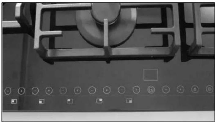
FIG. 11

BUTONS
ADJUSTMENT AND MODIFICATION WORK
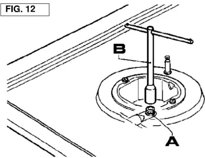
10) NOZZLES CHANGE
You can convert the burners for operation with various type of gas by installing nozzles appropriate for each gas. To perform this operation, remove burner heads. Using spanner wrench B loosen nozzle A (see Fig. 12) and replace it with the nozzle that corresponds to the gas type you want to use. It is recommended to tighten the nozzle securely.
After the above -mentioned replacement, a technician must perform burner adjustment as described in paragraph 9, install lead seals on available adjustment or pre-adjustment devices, and prepare a new factory label to replace the oil label, corresponding to the new setting of appliance gas supply. This label is in the bag for replaceable nozzles.
For installer's convenience, a table is provided below specifying burner power and heat capacity, nozzle diameters and operating pressures for various gases.

BURNER POSITION

| BURNERS | GASES | OPERATING PRESSURE | HEAT CAPACITY | NOZZLE DIAMETER 1/100 mm | HEAT CAPACITY (W) | ||||
| Pos. | NAME | g/h | I/h | MIN. | MAX. | EEBurner* | |||
| 1 | TRIPLE FLAME | G 30 - BUTANE | 28-30 | 276 | 100 B | 1800 | 3800 | 54.3 % | |
| G 31 - PROPANE | 37 | 271 | 100 B | 1800 | 3800 | ||||
| G 20 - NATURAL GAS | 20 | 357 | 145 A | 1800 | 3750 | ||||
| 2 | HIGH SPEED | G 30 - BUTANE | 28-30 | 204 | 83 | 800 | 2800 | 59.8 % | |
| G 31 - PROPANE | 37 | 200 | 83 | 800 | 2800 | ||||
| G 20 - NATURAL GAS | 20 | 267 | 117 Y | 800 | 2800 | ||||
| 3 | NORMAL SPEED, SMALL SIZE | G 30 - BUTANE | 28-30 | 98 | 58 | 650 | 1350 | 60.3 % | |
| G 31 - PROPANE | 37 | 96 | 58 | 650 | 1350 | ||||
| G 20 - NATURAL GAS | 20 | 133 | 85 Y | 650 | 1400 | ||||
| 4 | NORMAL SPEED | G 30 - BUTANE | 28-30 | 127 | 65 | 650 | 1750 | 55.0 % | |
| G 31 - PROPANE | 37 | 125 | 65 | 650 | 1750 | ||||
| G 20 - NATURAL GAS | 20 | 167 | 98 Z | 650 | 1750 | ||||
| 5 | AUXILIARY | G 30 - BUTANE | 28-30 | 73 | 50 | 550 | 1000 | NONE | |
| G 31 - PROPANE | 37 | 71 | 50 | 550 | 1000 | ||||
| G 20 - NATURAL GAS | 20 | 95 | 75 X | 550 | 1000 | ||||
- According to Regulation 66/2014 of the European Union which sets the guidelines for applying Directive 2009/125/CE, capacity calculation (EEgas burner) has been performed as per standards EN 30-2-1, latest revision for G-20.
ADJUSTMENT AND MODIFICATION WORK
Display of temperature inside the cooktop
The electronic board features a temperature sensor that allows monitoring temperature inside the cooktop directly on the timer display. To switch on this indication, press the "+" and "-" buttons of burner 1 simultaneously with buttons 12 and 13 (for 90~cm ), the "+" and "-" buttons of burner 5 simultaneously with buttons 12 and 13 (for 60~cm ) and hold them for at least 3 seconds. At this time using clock 11 for settings related to burner switch-off time programming, will be impossible.
To switch off internal temperature indication, press the buttons in the same order as for switching on.
Electronic self-test
Electronic boards continuously monitor their status. If hardware problems or faults occur inside the electronic board, including to the extent that may be dangerous for the end user, the appliance enters into "safe" state. In this state, the solenoids are switched off, and a code is shown on the display indicated the type of fault.
| Fault type | Displayed error code |
| One burner locked | B |
| Uncontrolled flame / flame sensor circuit failure on one burner | F |
| Main valve circuit failure | Flt00 |
| Voltage failure in reference circuit | Flt01 |
| Protection circuit failure | Flt02 |
| Microcontroller ports failure | Flt03 |
| EPROM failure | Flt04 |
| Valve control circuit failure | Flt05 |
| Limit exceeded for 5 attempts to release lock within 15 minutes | Flt06 |
| Power supply circuit failure | Flt08 |
| Sound alarm failure/ general failure | Flt09 |
| All burners locked | Flt0A |
| Logic control communication failure | Flt0[ |
| Control panel control failure | Flt0E |
ADJUSTMENT AND MODIFICATION WORK
DIMENSIONS
(electronic board)


MAINTENANCE
Before attempting any maintenance work disconnect the appliance from gas mains and electrical mains.
INSTALLATION TIPS
- The appliance is designed to work continuously for not more than 24 h (non-continuous operation system). When this time goes out, an adjustment break begins. During this break the appliance will check its performance efficiency.
- This automatic appliance is a safety-related device; its design modifications are prohibited. Modifications to this appliance design relieve the manufacturer from any liability whatsoever and cancel the warranty.
- The appliance conforms to all applicable national and European standards (such as EN 60335-1/EN 60335-2-102) in the field of electrical safety.
- Before starting to use the cooktop, carefully check the cables: a non-conforming cable can damage the appliance and put the system safety at risk.
- Turn the cooktop on and off only after the power supply is connected.
-
Do not let water droplets end up on the appliance.
-
Make sure that valve cables are not located near the high voltage cables of ignition transformer.
- Before switching on make sure that there are no foreign objects on the cooktop, particularly, in the control panel area.
After the cooktop is turned on, wait for a few seconds for the process of control panel automatic calibration to be completed. - In case of "partial" short circuit or insufficient insulation between line and earthing, voltage on the sensor electrode may drop to a level when appliance interlock is initiated, because it is not possible to accept the ignition signal.
- Touching the extra-low voltage (ELV) circuit is dangerous (only basic insulation as per EN 60730-1 is provided). Therefore, the appliance must ensure a level of electrical discharge protection for the user interface that is equivalent to double insulation.
MAINTENANCE
POWER SUPPLY CABLE TYPES AND CROSS-SECTIONS
| COOKTOP TYPE | CABLE TYPE | SINGLE-PHASE SUPPLY |
| Gas cooktop | H05 RR - F | Cross-section 3 x 0.75 mm² |
ATTENTION!
When replacing power supply cable, the installer must have at hand an earthing conductor (B) with a larger length than phase conductors (see Fig. 13) and comply with the requirements specified in paragraph 8.
WARNING: MAINTENANCE CAN BE CARRIED OUT ONLY AND EXCLUSIVELY BY AUTHORIZED PERSONNEL.
If the cable is malfunctioning or broken, remove it and do not touch. Also, disconnect the appliance from the socket and do not ignite flames. Contact your nearest authorized technical service center to eliminate this problem.

TECHNICAL DATA
DESCRIPTION
One electronic board allows for controlling a gas cooktop with 4-5 burners.
This product operates with Brahma VPC01 valves that enable adjustment of each burner power separately, using methane or liquefied petroleum gas.
The appliance is also equipped with user interface having a seven-segment display and touch panel.
MAIN SPECIFICATIONS
Main specifications are given below.
- A display with 7 red-colored segments and LCD displays for indicating power level of each individual burner, as well as for time and settings indication.
- Touch panel with 15 sensor zones for selecting power level for each burner individually, setting, control panel lock, and switching on/off.
- Five 24 VDC outputs for Brahma VPC01 modulating valves.
- 24 VDC output for main Brahma VPC01 valve after discharge pipe.
- RS232 interface for appliance testing.
- Five Faston inputs for flame sensor electrodes of five burners.
Output for 100-240 VAC igniter control.
- Control of pre-programed modulation levels in FLASH memory.
- Option to control two modulation tables (G20 and G30).
- Built-in procedure for minimum power level adjustment of each appliance burner.
- Power supply board designed using switching technology.
Day clock in 24 h format.
TECHNICAL DATA
Power supply:
100-240 VAC ±10%
Frequency:
50-60 Hz
Power consumption:
92 VA
Consumption in standby mode:
<1W
Switched-on transformer output contacts:
100-240 VAC ±10% - 250 mA - cosφ = 0.4
Sensor electrodes connection:
2.8 × 0.8 ~mm Faston
Operating temperature:
-10°C +85°C
Protection class:
IP 00
EN298 classification code:
| Special characteristics | Description | Code |
| 1° | Atmospheric monitor | A |
| 2° | Main burner direct ignition | M |
| 3° | Cycle repeat | C |
| 4° | Nonvolatile interlock | L |
| 5° | Setting time | X |
| 6° | Non-continuous operation | N |
Maximum length of external cables: ≤ 1m
Flame control
Flame sensor design uses the flame rectification process.
Minimum ionization current:
0.2 μA DC
Maximum ionization current: (supply voltage 264V_RMS
4.6 μA DC
Recommended ionization current:
3-5 times the minimum current
Maximum cable length:
1 m
Minimum electrode and measuring cable insulation resistance with earthing:
≥ 50M
Maximum electrode stray capacitance:
≤ 1 nF
Maximum short-circuit current
≤200μAAC
TIME
- wait time (TW):
1s
- safety time (TS):
4s
- response time in case of flame extinction:
3s
- transition waiting or transition ventilation time:
10s
-
waiting time for interlock triggered by uncontrollable flame:
-
ignition preparation time:
0s
- ignition attempts number:
TECHNICAL DATA INDICATED ON FACTORY LABEL
5 BURNERS (90)
(LEFT BURNER WITH
DOUBLE FLAME)
Category II2H3+
G 30 - Butane 28 - 30 mbar
G 31 -Propane 37 mbar
G 20 Natural gas 20 mbar
Qn Natural gas = 10.7kW
Qn Liquefied petroleum
gas = 10.7kW
∑ Qn Liquefied petroleum
gas = 778g / h (G30)
764 g/h (G31)
Voltage = 220 - 240V
Frequency = 50 - 60Hz
TECHNICAL DATA FOR ADJUSTMENT OF GAS USED IN THE APPLIANCE

If the kitchen is converted to another type of gas, follow the installation and operation instructions and replace the bottom label with the label stored in the spare parts bag.
TECHNICAL ASSISTANCE AND SPARE PARTS
This appliance was checked and adjusted before shipment from factory by experienced and specially trained personnel in order to ensure optimum performance.
Original spare parts are available only in our technical service centers and authorized sale points.
Each repair and adjustment, which may be required in future, must be performed by qualified personnel with utmost care and attention.
Therefore, we recommend to always contact the dealer where the product was purchased, or our nearest technical assistance center, specifying the brand, model, serial number and malfunction type of your appliance. Appliance data are specified on the factory label located on the appliance bottom part and on the label attached to the packaging box.
This information will help the technician find appropriate spare parts and promptly perform the work required.
We recommend that you note these data below so that you always have them at hand.
BRAND:
MODEL:
SERIES:

This appliance conforms to Directive of the European Union 2002/96/CE on electrical and electronic equipment designated as (Electrical and electronic waste). This Directive provides the general basis, valid throughout the entire territory of the European Union, for electrical and electronic waste distribution and disposal.
| USER SOLUTIONS | ||
| PROBLEM | CAUSE | SOLUTION |
| The gas ring burns unevenly | Contamination inside the gas ring head. | Remove foreign articles from gas ring head. |
| Wrong gas regulation | Contact with official technical support service of Pando. | |
| Gas ring flame suddenly changes / flashes | Wrong assembly of gas ring components. | Correctly install the gas ring components. |
| Flame is ignited with a great delay. | Wrong assembly of gas ring components. | Correctly install the gas ring components. |
| Flame foes out immediately after ignition | Ignition handle was released too early. | Hold the handle pressed within longer period of time and before finally releasing it, strongly press it. |
| Problem with thermocouple | Move thermocouple | |
| Contact with official technical support service of Pando. | ||
| Change in colour of grates within burning area. | Normal situation caused by high temperature or contamination. | Clean grates and components of gas ring using the appropriate metal cleaning agents |
| When pressing the control knob flame is not ignited (the spark plugs emit spark) | Gas absence or presence of residuals of contamination or cleaning agent on the spark plugs | Open the gas valve meter; clean the spark plugs as described in chapter "Cleaning" |
| When pressing the control knob flame is not ignited (the spark plugs don't emit spark) | Problems with plug or with ignition. | Contact with official technical support service of Pando. |
| Electric ignition doesn't operate. | Power supply absence. | Make sure that electrical connector is connected with the mains. Check, weather the meter is turn on. |
| Wrong assembly or ignition failure. | Contact with official technical support service of Pando. | |
| The spark plugs constantly emit spark. | Humidity | Power off for 24 hours and give the top part to dry; Make sure that all bushings are installed correctly. |
| Wrong assembly or fault of micro switch | Contact with official technical support service of Pando. | |
INOXPAN S.L.
TEL. 902 41 55 10 / FAX: 93 757 96 53
Use the above phone number, fax or e-mail to request technical assistance, under warranty or outside warranty. Please note that warranty covers only the work to eliminate appliance faults.
WARRANTY CERTIFICATE:
INOXPAN, S.L., being the manufacturer of this appliance, guarantees it for a period of two years from the moment of purchase, on the following terms.
- This warranty covers repair, spare parts and labor costs in the zones and countries where the appliance is available for sale.
- To use the warranty service right, upon demand of a technician of Inoxpan S.L (Pando) official authorized service it is necessary to provide this certificate, as well as purchase confirmation document (invoice), stating the seller's name, date of appliance transfer, appliance identification data and the price of its sale.
- A customer or end user is strongly advised to thoroughly read the operation and maintenance manual of the appliance, as well as its specifications, to correctly apply this warranty and better understand the principles of appliance operation.
- This warranty does not diminish rights provided to customers by current legislation, as well as rights provided under Royal Decree Law 1/2007 dated November 15th.
WARRANTY SERVICE RESTRICTIONS:
This warranty does not cover failures, accidents or faults of the appliance being the object of this warranty, if they have resulted from one of the following reasons:
a) If appliance installation has not been performed by an authorized professional, qualified electrician or electrical installer, or Pando's official authorized technical assistance service personnel, in line with the requirements of safety standards and gas and electrical work regulations.
b) External effects: atmospheric and geological phenomena, floods, insects, rodents, shocks and operation under nonconforming conditions of power, water, gas supply, etc.
c) Start-up and functional demonstration for a customer or end user.
d) Improper location, incorrect or defective installation of appliance, not complying with instructions in the appliance operation and installation manual.
e) Using jewellery made of metal, silicone, wood, plastic, or glass.
f) External defects, such as indents, rubbing marks, stains, or rust.
g) Accessories and wear parts, such as burners and their components, grates or fire bars, and others.
h) Absence of nameplate or appliance specifications label.
i) Modifications of gas composition.
j) Negligence, improper operation or use of appliance for purposes not specified or contained in the appliance documentation. This warranty covers only appliances used in households, and not in any professional, commercial or industrial operations.
k) Failures that appear as a result of appliance operation and normal wear.
I) Defects and damages that occurred during appliance transportation, unless liability therefor can be placed on Inoxpan S.L. under the terms provided in the catalog, section Return. In this case the claim must be presented within 24 hours from appliance delivery.
m) Repair, handling or modifications to the appliance done by persons other than Pando's official authorized service personnel. In this case the warranty is void.
n) Faults resulting from incorrect operation and periodical maintenance of the appliance, in breach of requirements in the appliance operation and installation manual.
This warranty is valid only if duly drawn up. It must contain the model and factory number, and be verified by the seal of sales company or distributor. An invoice must be enclosed specifying the purchase date.
| MODEL AND VERSION: | FACTORY NUMBER: | ||
| INSTALLER: | PURCHASING DATE: | ||
| SELLER: | SELLER'S SEAL: |
NOTES:
NOTES:

- INDICACOsParaA INSTALACAO
- 10) REMPLACEMENT DES BUSES
- Pando
- COOKTOPS DESCRIPTION
- FUNCTIONS available for user/technician:
- OPERATION
- 1) BURNERS
- Switching on the cooktop
- Burner ignition
- Setting burner flame level
- Switching off the burner
- Switching off all cooktop burners
- Burner switch-off time programming
- Programming simultaneous switch-off time for several burners
- Clock adjustment
- Releasing burner lock (Fig. 14)
- Child lock function
- Key lock release
- WARNING:
- WARNING AND USER TIPS:
- ATTENTION:
- ENERGY AND COOKWARE SAVING TIPS
- CLEANING
- 2) WORKTOP
- CERAMIC GLASS
- INSTALLATION
- TECHNICAL INFORMATION FOR INSTALLATION PERSONNEL
- INSTALLATION TIPS
- 3) COOKTOP BUILDING
- 4) COOKTOP FIXING
- IMPORTANT GUIDELINES TO BE FOLLOWED FOR INSTALLATION
- 5) ROOM VENTILATION
- 6) LOCATION AND AIRING
- 7) GAS SUPPLY
- IMPORTANT:
- 8) ELECTRICAL SUPPLY
- If connecting directly to electrical mains:
- ADJUSTMENT AND MODIFICATION WORK
- 9) MINIMUM BURNER POWER ADJUSTMENT PROCEDURE. (Fig. 15)
- Gas type selection (Fig. 16)
- 10) NOZZLES CHANGE
- Display of temperature inside the cooktop
- Electronic self-test
- DIMENSIONS
- (electronic board)
- MAINTENANCE
- ATTENTION!
- TECHNICAL DATA
- DESCRIPTION
- MAIN SPECIFICATIONS
- Maximum length of external cables: ≤ 1m
- Flame control
- TIME
- TECHNICAL DATA INDICATED ON FACTORY LABEL
- TECHNICAL DATA FOR ADJUSTMENT OF GAS USED IN THE APPLIANCE
- TECHNICAL ASSISTANCE AND SPARE PARTS
- WARRANTY CERTIFICATE:
- WARRANTY SERVICE RESTRICTIONS:
Brand : Pando
Model : PGA4490
Category : Cooker