
228541 - Measuring equipment SILVERLINE - Free user manual and instructions
Find the device manual for free 228541 SILVERLINE in PDF.

User questions about 228541 SILVERLINE
0 question about this device. Answer the ones you know or ask your own.
Ask a new question about this device
Download the instructions for your Measuring equipment in PDF format for free! Find your manual 228541 - SILVERLINE and take your electronic device back in hand. On this page are published all the documents necessary for the use of your device. 228541 by SILVERLINE.
USER MANUAL 228541 SILVERLINE
text_image
Diagram showing two hand-drawn symbols with checkmark and cross symbols, likely indicating a verification or approval process.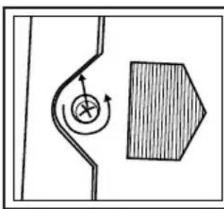
natural_image
Simple line drawing of a curved pipe with a circular arrow and a shaded rectangular block (no text or symbols)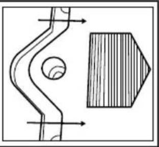
natural_image
Technical drawing of a mechanical component with cross-sectional view and hatched section (no text or symbols)IV
text_image
CAT.IV X CAT.III X CAT.I ✓ CAT.II ✓English ......4
Français ......8
Deutsch......12
Español......16
Italiano ......20
Nederlands ......24
Polski ......28
Introduction
Thank you for purchasing this Silverline tool. This manual contains information necessary for safe and effective operation of this product. This product has unique features and, even if you are familiar with similar products, it is necessary to read this manual carefully to ensure you fully understand the instructions. Ensure all users of the tool read and fully understand this manual.
Description of Symbols
The rating plate on your tool may show symbols. These represent important information about the product or instructions on its use.

Wear hearing protection
Wear eye protection
Wear breathing protection
Wear head protection

Wear hand protection

Read instruction manual

DO NOT use in rain or damp environments!

Caution!

Risk of electrocution!

Class II construction (double insulated for additional protection)

Conforms to relevant legislation and safety standards.

Environmental Protection
Waste electrical products should not be disposed of with household waste. Please recycle where facilities exist. Check with your local authority or retailer for recycling advice.
Technical Abbreviations Key
| V | Volts |
| ~, AC | Alternating current |
| A, mA | Ampere, milli-Amp |
| ∅ | Diameter |
| Hz | Hertz |
| ==, DC | Direct current |
| W, kW | Watt, kilowatt |
| Ω | Ohms (resistance) |
| F | Farad (capacitance) |
Specification
Display: 3-1/2 digits LCD (1999 max reading)
Ranges:......AC Current (200A, 1000A) 50-60Hz (clamp only),
AC Voltage (750V) 40-400Hz (probes only),
DC Voltage (1000V) (probes only),
Resistance (200Ω, 20kΩ) (probes only)
Insulation test 20MΩ, 2000MΩ (external unit)
Over-range indication: ......Figure '1' only shown on display
Negative polarity indication:......Figure "1" shown before value
Sampling rate: 3 times per second (approx.)
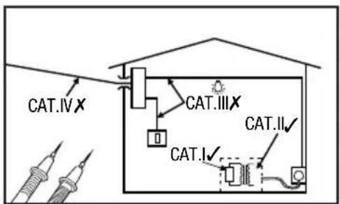
Meter category class: CAT. II, 1000V
Test leads: CAT. II, 1000V, 10A
Max. jaw opening/conductor size: 050mm
Operating temperature: 0°C - 40°C (<75% relative humidity)
Storage temperature: -10^ - 50^ (<85% relative humidity)
Battery: 9V 6F22 (PP3)
Dimensions (L x W x H): 240 x 102 x 47mm
Weight: 300g (including battery)
| The following specifications assume a 1-year calibration cycle and an operating temperature of 18°C to 28°C (64°F to 82°F) at relative humidity up to 80% unless otherwise noted. | |||
| Range Resolution | Accuracy± (% of reading) + number of least significant digits) | ||
| AC Current | |||
| Display: sine wave rms, average response | |||
| Frequency range: 50-60Hz | Overload protection: 1200A within 60 seconds | ||
| 200A 100mA ±(2.5% + 5) | |||
| 1000A 1A | <700A : ± (2.5% + 5), 700 800A : ± (5% + 5), >800A (>800A reading is only for reference) | ||
| AC Voltage | |||
| Input impedance : 9M Ω | Frequency response: 40Hz - 400Hz | ||
| Max. allowable input voltage : 750V DC/AC rms | Display: sine wave rms, average response | ||
| 750V | 1V | ±(2.0% + 5) | |
| DC Voltage | |||
| Input impedance : 9M Ω | Overload protection : 1000V DC/AC rms | ||
| 1000V 1V | ±(1.2% - 5) | ||
| Resistance | |||
| Overload protection : 250V DC/AC rms | |||
| 200Ω +Continuity | 100mΩ | ±(1.2% + 5) | |
| 200KΩ | 100 Ω | ±(1% + 3) | |
| Insulation Test | ||
| (requires external 500V insulation tester unit) | ||
| 20MΩ 10kΩ ±(2% + 2) | ||
| 2000MΩ 1MΩ | ≤500MΩ: ±(4% + 2) | |
| >500MΩ: ±(5% + 2) | ||
| Continuity | ||
 | If the resistance is less than about 50Ω, the built-in buzzer will soundBetween 50 Ω and 100 Ω resistance, the buzzer may not soundAt 100 Ω or more, the buzzer will not sound | |
Clamp Meter Safety
WARNING
The following are important safety points to avoid electric shock, personal injury and electrocution.
IMPORTANT: When using the probes, keep your fingers behind the finger guards on the probes
IMPORTANT: When an input terminal is connected to a dangerous live voltage, this voltage can occur at other terminals on the meter
IMPORTANT: Some functionality of this tool is only suitable for those skilled in electrical work. If in doubt about your capabilities, do not use this tool
a) Do not use the meter if it is damaged. Inspect the case. Pay particular attention to the insulation surrounding the connectors
b) Do not use the meter if it operates abnormally. It may give a false safe measurement. If in doubt, have the meter serviced
c) Inspect the test leads and probes for damaged insulation or exposed metal. Check the test leads for continuity regularly to prevent dangerous false readings. Replace damaged test leads before you use the meter
d) Do not operate the meter around explosive gas, vapour or dust
e) Do not use in wet or damp conditions and ensure the meter and test leads are completely dry before use. If using outside with open electrical connections, ensure they are protected from the possibility of rain
f) Do not apply more than the rated voltage, as marked on the meter, between terminals or between any terminal and earth ground
g) Do not exceed the rated voltage and current indicated on the test leads
h) Use caution when working with voltages above 30V ac rms, 42V peak, or 60V dc. Such voltages pose a shock hazard
i) Connect the common test lead before you connect the live test lead. When you disconnect test leads, disconnect the live test lead first
j) Do not operate the meter with the battery cover or portions of the case removed or loosened
k) Do not touch any exposed conductor directly with hands or skin
I) Do not use the supplied test leads with other equipment. This could damage the test leads or the other equipment and create a safety hazard
m) Do not hold the meter beyond the clamping guard. Keep your fingers behind the raised plastic edge next to clamp mechanism
n) Do not change settings or make adjustments to the meter close to live cables or exposed conductors. Change settings and make adjustments in a safe area
o) Do not ground yourself when taking electrical measurements. Ensure you are isolated by wearing rubber shoes with no part of your body resting against an earthed surface, for example pipes, fixtures etc.
Product Familiarisation
| 1 Clamp |
| 2 Clamp Guard |
| 3 Data Hold Button |
| 4 Dial |
| 5 EKT Socket |
| 6 COM Socket |
| 7 Vrist Strap |
| 8 Voltage/Resistance Socket |
| 9 LCD Display |
| 10 Clamp Lever |
| 11 Test Lead Connector Covers |
| 12 Positive/Live Probe |
| 13 Negative/Common Probe |
| 14 Test Lead Connectors |
Intended Use
A hand-held battery-powered clamp multimeter optimised for electrical AC and DC voltage measuring. Also measures AC current using a single conductor within the clamp mechanism typically found in commercial or industrial installations. Certified for CAT. I & II use. Not suitable for CAT. III & IV. Secondary functions are resistance measurement and an audible continuity check.
Unpacking Your Tool
- Carefully unpack and inspect your tool. Fully familiarise yourself with all its features and functions
- Ensure that all parts of the tool are present and in good condition. If any parts are missing or damaged, have such parts replaced before attempting to use this tool
Before Use
Inserting Battery
Note: When the battery has low charge will be indicated in the LCD Display (9). It is important the battery is replaced before use to prevent erratic and incorrect measurement.
- Remove the screw and slide the battery compartment cover forward as indicated (Fig. III)
- Fit a new 9V 6F22 (PP3) battery (branded alkaline recommended) ensuring the polarity is correct as indicated in the battery compartment
- Slide the compartment cover back on and refit the screw
Connecting test leads
For all modes except AC current measurement the test leads need to be fitted.
- Remove the Test Lead Connector Covers (11) if fitted
- Connect the black Test Lead Connector (14) to the COM Socket (6)
- Connect the red Test Lead Connector to the Voltage/Resistance Socket (B) for AC and DC voltage measurement resistance measurements and continuity checks
Operation
Note: The dial has duplicated range positions on the left and right side. There is no functional difference between using the same value on the left or right side.
Data Hold Button
- Press in the Data Hold Button (3) to keep a reading on the LCD screen that has been measured. Release the Data Hold Button to allow a new measurement to be shown
IMPORTANT: Before measuring (especially a high voltage or current), test a known value (voltage, current or resistance) to ensure the meter is working correctly with any danger indicated.
AC Current Measurement
IMPORTANT: Make sure that all test leads are disconnected from the meter
Note: This mode is typically used in commercial or industrial installations and is not functional for standard domestic AC cables which have an insulated sleeve covering individually insulated live and neutral conductors. Do not remove important safety insulation in order to take a measurement.
- Rotate the Dial (4) to the 1000A\~ setting, as shown approximately bottom left on Fig. I
- Make sure the Data Hold Button (3) is not pressed
- Press in the Clamp Lever (10) to open the Clamp (1) and insert one conductor ONLY into the Clamp Area (2) (Fig. II). It is impossible to make measurements when two or three conductors are clamped at the same time
- If the display indicates one or more leading zeros, shift to the 200A\~ range to improve the resolution of the measurement
- Allow a few seconds for the reading to stabilise. To read the display more clearly, push in the Data Hold Button, unclamp the conductor and move the meter to a more convenient location
AC Voltage Measurement
- Set the Dial (4) to the 750V\~ position. Do not use the meter if you are unsure whether the voltage exceeds 750V.
- Connect the probes to the circuit under test in parallel and take the reading
DC Voltage Measurement
- Set Dial (4) to the 1000V==
- Do not use the meter if you are unsure whether the voltage exceeds 1000V
- Connect the probes to the circuit under test in parallel and take the reading. A '-' will precede a negative value in the LCD Display (9)
IMPORTANT: Disconnect circuit power and discharge all capacitors before testing resistance and continuity.
Resistance Measurement
- Set the Dial (4) to 200Ω or 20kΩ position
- Connect test lead probes to the circuit or cable to be tested and take the resistance reading
- With the test lead probes open the LCD Display (9) should indicate '1' (over range)
- Connecting the Positive/Live Probe (12) and Negative/Common Probe (13) together will indicate '0.00' on the LCD Display
Continuity Check
This allows fast checking of continuity using an audible buzzer.
- Set the Dial (4) to 200Ω position
- Connect the test lead probes to the circuit or cable to be checked for continuity
- For resistance readings:
50Ω or less · the buzzer will sound
50 - 100Ω - the buzzer may not sound
100Ω or greater resistance - the buzzer will not sound
Insulation Resistance Test
- Follow the instructions provided with the Insulation Tester
Troubleshooting
Problem Possible cause Solution
| Display figure is frozen Data Hold Button (3) is pressed in or stuck Release Data Hold Button | ||
| Buzzing when using clamp - Normal operation | ||
| Lowest digit of value is unstable - | Normal operation for some measuring | |
| Display value erratic | Intermittent connection in one of the test leads Replace Battery low | test leads ensuring they are the correct specification |
| Replace battery |
Maintenance
Cleaning
- Periodically wipe the case with a damp cloth and mild detergent. Do not use abrasives or solvents
- Dirt or moisture in the meter sockets and test lead connectors can affect readings. To clean remove any loose dirt/debris first and then use a cotton bud dipped in neat alcohol cleaning fluid. Work the cotton bud around the full area of each connector and socket.
Storage
Switch off the meter and disconnect the test leads. Refit the Test Lead Connector Covers (11) and store meter, test leads and these instructions in the supplied case. For long-term storage, remove the battery.
Disposal
Always adhere to national regulations when disposing of tools that are no longer functional and are not viable for repair.
- Do not dispose of waste electrical and electronic equipment (WEEE), with household waste
- Contact your local waste disposal authority for information on the correct way to dispose of tools
Silverline Tools Guarantee
This Silverline product comes with a 3 year guarantee
Register this product at www.silverlinetools.com within 30 days of purchase in order to qualify for the 3 year guarantee. Guarantee period begins according to the date of purchase on your sales receipt.
Registering your purchase
Registration is made at silverlinetools.com by selecting the Guarantee Registration button. You will need to enter:-
- Your personal details
• Details of the product and purchase information
Once this information is entered your guarantee certificate will be created in PDF format for you to print out and keep with your purchase.
Terms & Conditions
Guarantee period becomes effective from the date of retail purchase as detailed on your sales receipt.
PLEASE KEEP YOUR SALES RECEIPT
If this product develops a fault within 30 days of purchase, return it to the stockist where it was purchased, with your receipt, stating details of the fault. You will receive a replacement or refund.
If this product develops a fault after the 30 day period, return it to:
Silverline Tools Service Centre
PO Box 2988
Yeovil
BA21 1WU, UK
The guarantee claim must be submitted during the guarantee period.
You must provide the original sales receipt indicating the purchase date, your name, address and place of purchase before any work can be carried out.
You must provide precise details of the fault requiring correction.
Claims made within the guarantee period will be verified by Silverline Tools to establish if the deficiencies are related to material or manufacturing of the product.
Carriage will not be refunded. Items for return must be in a suitably clean and safe state for repair, and should be packaged carefully to prevent damage or injury during transportation. We may reject unsuitable or unsafe deliveries.
All work will be carried out by Silverline Tools or its authorized repair agents.
The repair or replacement of the product will not extend the period of guarantee
Defects recognised by us as being covered by the guarantee shall be corrected by means of repair of the tool, free of charge (excluding carriage charges) or by replacement with a tool in perfect working order.
Retained tools, or parts, for which a replacement has been issued, will become the property of Silverline Tools.
The repair or replacement of your product under guarantee provides benefits which are additional to and do not affect your statutory rights as a consumer.
What is covered:
The repair of the product, if it can be verified to the satisfaction of Silverline Tools that the deficiencies were due to faulty materials or workmanship within the guarantee period.
If any part is no longer available or out of manufacture, Silverline Tools will replace it with a functional replacement part.
Use of this product in the EU.
What is not covered:
Silverline Tools does not guarantee repairs required as a result of:
Normal wear and tear caused by use in accordance with the operating instructions eg blades, brushes, belts, bulbs, batteries etc.
The replacement of any provided accessories drill bits, blades, sanding sheets, cutting discs and other related items.
Accidental damage, faults caused by negligent use or care, misuse, neglect, careless operation or handling of the product.
Use of the product for anything other than normal domestic purposes.
Change or modification of the product in any way.
Use of parts and accessories which are not genuine Silverline Tools components.
Faulty installation (except installed by Silverline Tools).
Repairs or alterations carried out by parties other than Silverline Tools or its authorized repair agents.
Claims other than the right to correction of faults on the tool named in these guarantee conditions are not covered by the guarantee.
CE Declaration of Conformity
The undersigned: Mr Darrell Morris
as authorised by: Silverline Tools
Declares that
This declaration has been issued under the sole responsibility of the manufacturer.
The object of the declaration is in conformity with the relevant Union harmonisation Legislation.
Identification code: 228541
Description: Digital Clamp Meter
• Low Voltage Directive 2014/35/EU
• EMC Directive 2014/30/EU
• RoHS Directive 2011/65/EU
• EN61010-1:2010, EN61010-2-030:2010
• EN61010-031:2015, EN61010-2-032
• EN61010-2-033
• EN61326-1:2013
• EN61326-2-2:2013
Notified body: Most Compliance Laboratory
The technical documentation is kept by: Silverline Tools
Date: 26/06/15
Signed:

Mr Darrell Morris
Managing Director
Name and address of the manufacturer:
Powerbox International Limited, Company No. 06897059. Registered address:
Powerbox, Boundary Way, Lufton Trading Estate, Yeovil, Somerset BA22 8HZ, United Kingdom.
Introduction
Silverline Tools Service Centre
PO Box 2988
Yeovil
Silverline Tools Service Centre
PO Box 2988
Yeovil
BA21 1WU, GB
Silverline Tools Service Centre
PO Box 2988
Yeovil
BA21 1WU, GB
Silverline Tools Service Centre
PO Box 2988
Yeovil
BA21 1WU, UK
Powerbox International Limited, Company No. 06897059. Registered address: Powerbox, Boundary
Way, Lufton Trading Estate, Yeovil, Somerset BA22 8HZ, United Kingdom.
text_image
JUNANALIC 56.66GB 3 Year Guarantee *Register online within 30 days. Terms and Conditions apply.