USER MANUAL 9741J MAKITA
GB Wheel Sander Instruction Manual
natural_image
Line drawing of a mechanical tool or device with no visible text, numbers, or symbols
004566 004567
1
004568 004569
4
3
004570 0045716
5
7
001145 004572
8
Explanation of general view
| 1 Wing nut | 7 Output shaft | 13 Joint |
| 2 Front roller | 8 H e x w r e n c | 14 Grip |
| 3 Switch trigger | 9 Notch | 15 Handle |
| 4 Lock button | 10 Pin | 16 Limit mark |
| 5 Spindle | 11 Dust port | 17 Screwdriver |
| 6 Wheel | 12 Cover plate | 18 Brush holder cap |
SPECIFICATIONS
Model 9741
Wheel size (Diameter x Width) 100 x 120 mm
No load speed (min ^-1 ) 3,500
Dimensions (L x W x H) 310 x 185 x 182 mm
Net weight 4.2 kg
Safety class ....../H
- Due to our continuing program of research and development, the specifications herein are subject to change without notice.
- Specifications may differ from country to country.
• Weight according to EPTA-Procedure 01/2014
ENE053-1
Intended use
The tool is intended for removing paint with slit paper wheel and fine metal cleaning with wire brush wheel.
ENF002-2
Power supply
The tool should be connected only to a power supply of the same voltage as indicated on the nameplate, and can only be operated on single-phase AC supply. They are double-insulated and can, therefore, also be used from sockets without earth wire.
GEA010-2
WARNING: Read all safety warnings, instructions, illustrations and specifications provided with this power tool. Failure to follow all instructions listed below may result in electric shock, fire and/or serious injury.
Save all warnings and instructions for future reference.
The term “power tool” in the warnings refers to your mains-operated (corded) power tool or battery-operated (cordless) power tool.
GEB146-1
WHEEL SANDER SAFETY WARNINGS
-
Hold the power tool by insulated gripping surfaces, because the wheel may contact its own cord. Cutting a "live" wire may make exposed metal parts of the power tool "live" and could give the operator an electric shock.
-
Always use safety glasses or goggles. Ordinary eye or sun glasses are NOT safety glasses.
-
Inspect for and remove foreign matter such as nails, screws, etc. from the workpiece surface before operation.
-
Secure the workpiece firmly.
-
Do not wear gloves during operation.
-
Hold the tool firmly with both hands.
-
Keep hands away from rotating parts.
-
Do not leave the tool running. Operate the tool only when hand-held.
- Never attempt to use with the tool held upside down in a vise, etc.
- Some material contains chemicals which may be toxic. Take caution to prevent dust inhalation and skin contact. Follow material supplier safety data.
- Use of this tool to sand some products, paints and wood could expose user to dust containing hazardous substances. Use appropriate respiratory protection.
SAVE THESE INSTRUCTIONS.
WARNING:
DO NOT let comfort or familiarity with product (gained from repeated use) replace strict adherence to safety rules for the subject product. MISUSE or failure to follow the safety rules stated in this instruction manual may cause serious personal injury.
FUNCTIONAL DESCRIPTION
CAUTION:
- Always be sure that the tool is switched off and unplugged before adjusting or checking function on the tool.
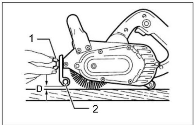
Adjusting front roller (Fig. 1)
The front roller allows you to apply uniform pressure to the workpiece. To adjust the front roller, set the tool on a flat surface and loosen the wing nut. Adjust the front roller up or down until the clearance distance (D) is about 2 mm. Tighten the wing nut securely.
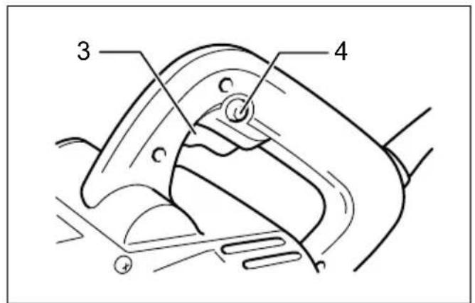
Switch action (Fig. 2)
CAUTION:
- Before plugging in the tool, always check to see that the switch trigger actuates properly and returns to the "OFF" position when released.
To start the tool, simply pull the switch trigger. Release the switch trigger to stop.
For continuous operation, pull the switch trigger and then push in the lock button.
To stop the tool from the locked position, pull the switch trigger fully, then release it.
ASSEMBLY
CAUTION:
- Always be sure that the tool is switched off and unplugged before carrying out any work on the tool.
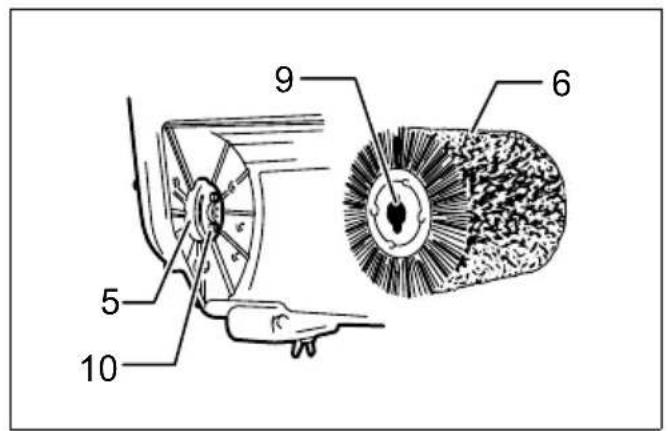
Installing or removing wheel (Fig. 3 & 4)
To remove the wheel, insert one hex wrench into the end of the spindle and another hex wrench into the end of the output shaft. Turn the hex wrench in the output shaft clockwise while securely holding the hex wrench in the spindle so that the wheel cannot revolve. Pull the output shaft out from the wheel. Move the wheel slightly away from the spindle and remove the wheel from the tool.
NOTE:
- The output shaft has a left hand thread.
To install the wheel, follow the removal procedures in reverse. When installing it, be sure to align the notches in the wheel with the pins on the spindle.
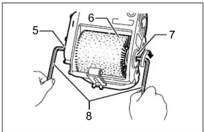
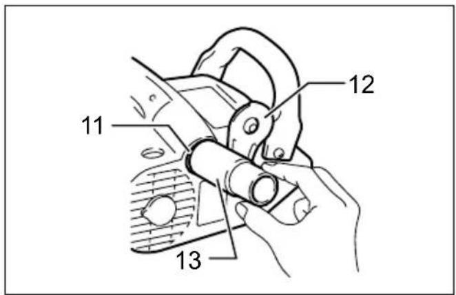
Connecting to dust collector (Fig. 5)
The use of a dust collector makes sanding operations clean and dust collection easy. To connect a dust collector, open the dust port by sliding the cover plate up and in a clockwise direction. Attach the joint onto the dust port. Now a dust collector can be connected to this tool.
CAUTION:
- When not using a dust collector, close the dust port opening with the cover plate.
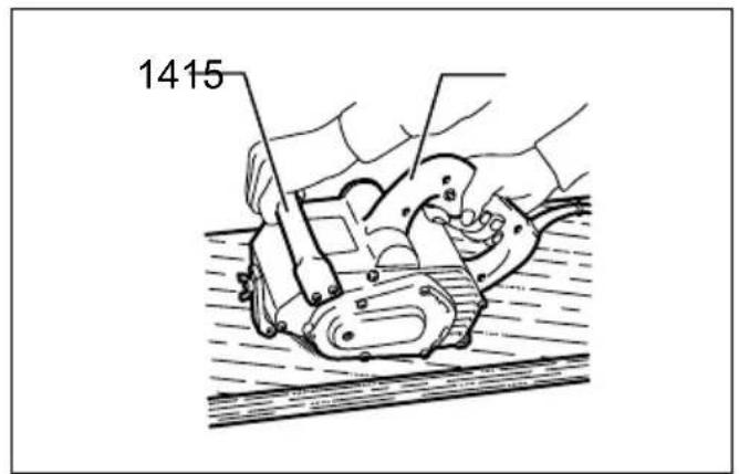
OPERATION (Fig. 6)
Hold the tool firmly with both hands on the handle and the grip in front. Place the tool on the workpiece surface and move the tool gently forward and backward while applying slight downward pressure.
CAUTION:
- The tool should not be in contact with the workpiece surface when you turn the tool on or off. Damage to the tool or the workpiece surface and injury to the operator may result.
- Apply slight downward pressure only. Excessive pressure may decrease tool efficiency, shorten wheel service life and possibly gouge the workpiece surface.
MAINTENANCE
CAUTION:
- Always be sure that the tool is switched off and unplugged before attempting to perform inspection or maintenance.
- Never use gasoline, benzine, thinner, alcohol or the like. Discoloration, deformation or cracks may result.
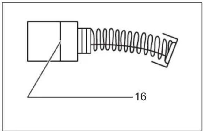
Replacing carbon brushes
Remove and check the carbon brushes regularly. Replace them when they are worn down to the limit mark. Keep the carbon brushes clean and free to slip in the holders. Both carbon brushes should be replaced at the same time. Use only identical carbon brushes.
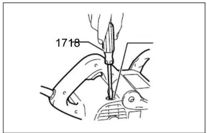
(Fig. 7)
Use a screwdriver to remove the brush holder caps. Take out the worn carbon brushes, insert the new ones and secure the brush holder caps. (Fig. 8)
To maintain product SAFETY and RELIABILITY, repairs, any other maintenance or adjustment should be performed by Makita Authorized Service Centers, always using Makita replacement parts.
OPTIONAL ACCESSORIES
CAUTION:
- These accessories or attachments are recommended for use with your Makita tool specified in this manual. The use of any other accessories or attachments might present a risk of injury to persons. Only use accessory or attachment for its stated purpose.
If you need any assistance for more details regarding these accessories, ask your local Makita Service Center.
- Nylon brush wheel
- Slit paper wheel 120 - 40
- Wire brush wheel 120
• Cotton buff wheel 120
- Joint
- Hex wrench
NOTE:
- Some items in the list may be included in the tool package as standard accessories. They may differ from country to country.
ENG905-1
Noise
The typical A-weighted noise level determined according to EN62841:
Sound pressure level ( L_pA ): 89 dB (A)
Sound power level (LWA): 100 dB (A)
Uncertainty (K): 3 dB (A)
ENG907-1
NOTE:
- The declared noise emission value(s) has been measured in accordance with a standard test method and may be used for comparing one tool with another.
- The declared noise emission value(s) may also be used in a preliminary assessment of exposure.
WARNING:
- Wear ear protection.
- The noise emission during actual use of the power tool can differ from the declared value(s) depending on the ways in which the tool is used especially what kind of workpiece is processed.
- Be sure to identify safety measures to protect the operator that are based on an estimation of exposure in the actual conditions of use (taking account of all parts of the operating cycle such as the times when the tool is switched off and when it is running idle in addition to the trigger time).
ENG900-1
Vibration
The vibration total value (tri-axial vector sum) determined according to EN62841:
Work mode: sanding metal plate
Vibration emission ( a_h ): 5.5 m/s ^2
Uncertainty (K): 1.5 m/s ^2
Work mode: sanding wood
Vibration emission ( a_h ): 3.0 m/s ^2
Uncertainty (K): 1.5 m/s ^2
NOTE:
- The declared vibration total value(s) has been measured in accordance with a standard test method and may be used for comparing one tool with another.
- The declared vibration total value(s) may also be used in a preliminary assessment of exposure.
WARNING:
- The vibration emission during actual use of the power tool can differ from the declared value(s) depending on the ways in which the tool is used especially what kind of workpiece is processed.
- Be sure to identify safety measures to protect the operator that are based on an estimation of exposure in the actual conditions of use (taking account of all parts of the operating cycle such as the times when the tool is switched off and when it is running idle in addition to the trigger time).
For European countries only
The EC declaration of conformity is included as Annex A to this instruction manual.
Descriptif
OPTIONELE ACCESSOIRES
LET OP:


