TW001GM201 - Screwdriver MAKITA - Free user manual and instructions
Find the device manual for free TW001GM201 MAKITA in PDF.
Download the instructions for your Screwdriver in PDF format for free! Find your manual TW001GM201 - MAKITA and take your electronic device back in hand. On this page are published all the documents necessary for the use of your device. TW001GM201 by MAKITA.
USER MANUAL TW001GM201 MAKITA
Cordless Impact Wrench INSTRUCTION MANUAL 4
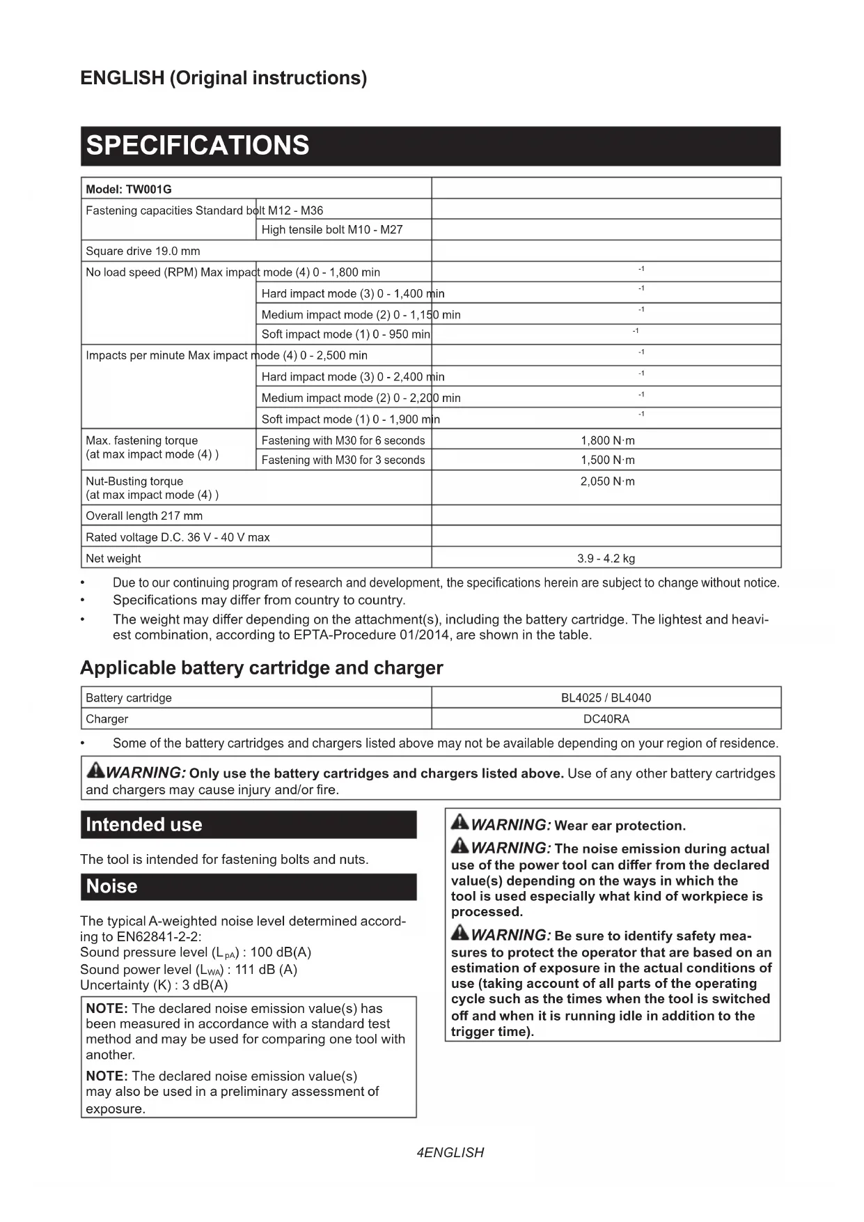
Max. fastening torque (at max impact mode (4) ) Fastening with M30 for 6 seconds 1,800 N·m Fastening with M30 for 3 seconds 1,500 N·m Nut-Busting torque (at max impact mode (4) ) 2,050 N·m Overall length 217 mm Rated voltage D.C. 36 V - 40 V max Net weight 3.9 - 4.2 kg
Due to our continuing program of research and development, the specications herein are subject to change without notice.
- Specications may dier from country to country.
- The weight may dier depending on the attachment(s), including the battery cartridge. The lightest and heavi- est combination, according to EPTA-Procedure 01/2014, are shown in the table. Applicable battery cartridge and charger Battery cartridge BL4025 / BL4040 Charger DC40RA
Some of the battery cartridges and chargers listed above may not be available depending on your region of residence.
WARNING: Only use the battery cartridges and chargers listed above. Use of any other battery cartridges
and chargers may cause injury and/or re. Intended use The tool is intended for fastening bolts and nuts. Noise The typical A-weighted noise level determined accord- ing to EN62841-2-2: Sound pressure level (L
) : 111 dB (A) Uncertainty (K) : 3 dB(A) NOTE: The declared noise emission value(s) has been measured in accordance with a standard test method and may be used for comparing one tool with another. NOTE: The declared noise emission value(s) may also be used in a preliminary assessment of exposure.
WARNING: Wear ear protection.
WARNING: The noise emission during actual
use of the power tool can dier from the declared value(s) depending on the ways in which the tool is used especially what kind of workpiece is processed.
WARNING: Be sure to identify safety mea-
sures to protect the operator that are based on an estimation of exposure in the actual conditions of use (taking account of all parts of the operating cycle such as the times when the tool is switched o and when it is running idle in addition to the trigger time).5 ENGLISH Vibration The vibration total value (tri-axial vector sum) deter- mined according to EN62841-2-2: Work mode: impact tightening of fasteners of the maxi- mum capacity of the tool Vibration emission (a
NOTE: The declared vibration total value(s) has been measured in accordance with a standard test method and may be used for comparing one tool with another. NOTE: The declared vibration total value(s) may also be used in a preliminary assessment of exposure.
The vibration emission during actual use of the power tool can dier from the declared val- ue(s) depending on the ways in which the tool is used especially what kind of workpiece is processed.
Be sure to identify safety measures to protect the operator that are based on an estima- tion of exposure in the actual conditions of use (tak- ing account of all parts of the operating cycle such as the times when the tool is switched o and when it is running idle in addition to the trigger time). EC Declaration of Conformity For European countries only The EC declaration of conformity is included as Annex A to this instruction manual. SAFETY WARNINGS General power tool safety warnings
WARNING: Read all safety warnings, instruc-
tions, illustrations and specications provided with this power tool. Failure to follow all instructions listed below may result in electric shock, re and/or serious injury. Save all warnings and instruc- tions for future reference. The term "power tool" in the warnings refers to your mains-operated (corded) power tool or battery-operated (cordless) power tool. Cordless impact wrench safety warnings
1. Hold the power tool by insulated gripping
surfaces, when performing an operation where the fastener may contact hidden wiring. Fasteners contacting a "live" wire may make exposed metal parts of the power tool "live" and could give the operator an electric shock.
2. Wear ear protectors.
3. Check the impact socket carefully for wear,
cracks or damage before installation.
4. Hold the tool rmly.
5. Keep hands away from rotating parts.
6. Do not touch the impact socket, bolt, nut or the
workpiece immediately after operation. They may be extremely hot and could burn your skin.
7. Always be sure you have a rm footing.
Be sure no one is below when using the tool in high locations.
8. The proper fastening torque may dier
depending upon the kind or size of the bolt. Check the torque with a torque wrench. SAVE THESE INSTRUCTIONS.
WARNING: DO NOT let comfort or familiarity
with product (gained from repeated use) replace strict adherence to safety rules for the subject product. MISUSE or failure to follow the safety rules stated in this instruction manual may cause serious personal injury. Important safety instructions for battery cartridge
Before using battery cartridge, read all instruc- tions and cautionary markings on (1) battery char- ger, (2) battery, and (3) product using battery.
2. Do not disassemble or tamper the battery
cartridge. It may result in a re, excessive heat, or explosion.
3. If operating time has become excessively
shorter, stop operating immediately. It may result in a risk of overheating, possible burns and even an explosion.
4. If electrolyte gets into your eyes, rinse them
out with clear water and seek medical atten- tion right away. It may result in loss of your eyesight.
5. Do not short the battery cartridge:
(1) Do not touch the terminals with any con- ductive material. (2) Avoid storing battery cartridge in a con- tainer with other metal objects such as nails, coins, etc. (3) Do not expose battery cartridge to water or rain. A battery short can cause a large current ow, overheating, possible burns and even a breakdown.
6. Do not store and use the tool and battery car-
tridge in locations where the temperature may reach or exceed 50 °C (122 °F).
7. Do not incinerate the battery cartridge even if
it is severely damaged or is completely worn out. The battery cartridge can explode in a re.
8. Do not nail, cut, crush, throw, drop the battery
cartridge, or hit against a hard object to the battery cartridge. Such conduct may result in a re, excessive heat, or explosion.
9. Do not use a damaged battery.
The contained lithium-ion batteries are subject to the Dangerous Goods Legislation requirements. For commercial transports e.g. by third parties, forwarding agents, special requirement on pack- aging and labeling must be observed.6 ENGLISH For preparation of the item being shipped, consult- ing an expert for hazardous material is required. Please also observe possibly more detailed national regulations. Tape or mask o open contacts and pack up the battery in such a manner that it cannot move around in the packaging.
11. When disposing the battery cartridge, remove
it from the tool and dispose of it in a safe place. Follow your local regulations relating to disposal of battery.
12. Use the batteries only with the products
specied by Makita. Installing the batteries to non-compliant products may result in a re, exces- sive heat, explosion, or leak of electrolyte.
13. If the tool is not used for a long period of time,
the battery must be removed from the tool.
14. During and after use, the battery cartridge may
take on heat which can cause burns or low temperature burns. Pay attention to the han- dling of hot battery cartridges.
15. Do not touch the terminal of the tool imme-
diately after use as it may get hot enough to cause burns.
16. Do not allow chips, dust, or soil stuck into the
terminals, holes, and grooves of the battery cartridge. It may result in poor performance or breakdown of the tool or battery cartridge.
17. Unless the tool supports the use near
high-voltage electrical power lines, do not use the battery cartridge near a high-voltage elec- trical power lines. It may result in a malfunction or breakdown of the tool or battery cartridge.
18. Keep the battery away from children.
SAVE THESE INSTRUCTIONS. CAUTION: Only use genuine Makita batteries. Use of non-genuine Makita batteries, or batteries that have been altered, may result in the battery bursting causing res, personal injury and damage. It will also void the Makita warranty for the Makita tool and charger. Tips for maintaining maximum battery life
1. Charge the battery cartridge before completely
discharged. Always stop tool operation and charge the battery cartridge when you notice less tool power.
2. Never recharge a fully charged battery car-
tridge. Overcharging shortens the battery service life.
3. Charge the battery cartridge with room tem-
perature at 10 °C - 40 °C (50 °F - 104 °F). Let a hot battery cartridge cool down before charging it.
4. When not using the battery cartridge, remove
it from the tool or the charger.
5. Charge the battery cartridge if you do not use
it for a long period (more than six months). FUNCTIONAL DESCRIPTION CAUTION: Always be sure that the tool is switched o and the battery cartridge is removed before adjusting or checking function on the tool. Installing or removing battery cartridge CAUTION: Always switch o the tool before installing or removing of the battery cartridge. CAUTION: Hold the tool and the battery car- tridge rmly when installing or removing battery cartridge. Failure to hold the tool and the battery cartridge rmly may cause them to slip o your hands and result in damage to the tool and battery cartridge and a personal injury. ► Fig.1: 1. Red indicator 2. Button 3. Battery cartridge To remove the battery cartridge, slide it from the tool while sliding the button on the front of the cartridge. To install the battery cartridge, align the tongue on the battery cartridge with the groove in the housing and slip it into place. Insert it all the way until it locks in place with a little click. If you can see the red indicator on the upper side of the button, it is not locked completely. CAUTION: Always install the battery cartridge fully until the red indicator cannot be seen. If not, it may accidentally fall out of the tool, causing injury to you or someone around you. CAUTION: Do not install the battery cartridge forcibly. If the cartridge does not slide in easily, it is not being inserted correctly. Tool / battery protection system The tool is equipped with a tool/battery protection sys- tem. This system automatically cuts o the power to extend tool and battery life. The tool will automatically stop during operation if the tool or battery is placed under one of the following conditions: Overload protection This protection works when the tool is operated in a manner that causes it to draw an abnormally high cur- rent. In this situation, turn the tool o and stop the appli- cation that caused the tool to become overloaded. Then turn the tool on to restart. Overheat protection When the tool is overheated, the tool stops automati- cally and the lamps blink. In this situation, let the tool and battery cool before turning the tool on again. Overdischarge protection This protection works when the remaining battery capacity gets low. In this situation, remove the battery from the tool and charge the battery.7 ENGLISH Indicating the remaining battery capacity Press the check button on the battery cartridge to indi- cate the remaining battery capacity. The indicator lamps light up for a few seconds. ► Fig.2: 1. Indicator lamps 2. Check button Indicator lamps Remaining capacity Lighted O Blinking 75% to 100% 50% to 75% 25% to 50% 0% to 25% Charge the battery. The battery may have malfunctioned. NOTE: Depending on the conditions of use and the ambient temperature, the indication may dier slightly from the actual capacity. Switch action ► Fig.3: 1. Switch trigger CAUTION: Before installing the battery car- tridge into the tool, always check to see that the switch trigger actuates properly and returns to the "OFF" position when released. To start the tool, simply pull the switch trigger. Tool speed is increased by increasing pressure on the switch trigger. Release the switch trigger to stop. NOTE: The tool automatically stops when you keep pulling the switch trigger for about 6 minutes. NOTE: When full speed mode is turned on, the rota- tion speed becomes fastest even if you do not pull the switch trigger fully. For detail information, refer to the section of full speed mode. Lighting up the front lamp CAUTION: Do not look in the light or see the source of light directly. ► Fig.4: 1. Lamp ► Fig.5: 1. Button To turn on the lamp status, press the button for one second. To turn o the lamp status, press the but- ton for one second again. With the lamp status ON, pull the switch trigger to turn on the lamp. To turn o, release it. The lamp goes out approximately 10 seconds after releasing the switch trigger. With the lamp status OFF, the lamp does not turn on even if pulling the trigger. NOTE: To conrm the lamp status, pull the trigger. When the lamp lights up by pulling the switch trigger, the lamp status is ON. When the lamp does not come on, the lamp status is OFF. NOTE: When the tool is overheated, the light ashes for one minute, and then the LED display goes o. In this case, cool down the tool before operating again. NOTE: Use a dry cloth to wipe the dirt o the lens of the lamp. Be careful not to scratch the lens of lamp, or it may lower the illumination. NOTE: While pulling the switch trigger, the lamp status cannot be changed. NOTE: For approximately 10 seconds after releasing the switch trigger, the lamp status can be changed. Reversing switch action ► Fig.6: 1. Reversing switch lever CAUTION: Always check the direction of rotation before operation. CAUTION: Use the reversing switch only after the tool comes to a complete stop. Changing the direction of rotation before the tool stops may dam- age the tool. CAUTION: When not operating the tool, always set the reversing switch lever to the neu- tral position. This tool has a reversing switch to change the direction of rotation. Depress the reversing switch lever from the A side for clockwise rotation or from the B side for coun- terclockwise rotation. When the reversing switch lever is in the neutral posi- tion, the switch trigger cannot be pulled.8 ENGLISH Changing the application mode Changing the impact force You can change the impact force in four steps: 4 (max), 3 (hard), 2 (medium), and 1 (soft). This allows a tightening suitable to the work. The level of the impact force changes every time you press the button . You can change the impact force within approximately one minute after releasing the switch trigger. NOTE: You can extend the time to change the impact force approximately one minute if you press the but- ton or . ► Fig.7 Application mode (Impact force grade displayed on panel) Maximum blows Purpose 4 (Max) 2,500 min
(/min) Tightening with the maximum force and speed. Tightening when the force and the speed are desired. 3 (Hard) 2,400 min
(/min) Tightening with less force and speed than Max mode (easier to control than Max mode). Tightening when the force and the speed are desired. 2 (Medium) 2,200 min
(/min) Tightening when a good nishing is needed. Tightening when you need good control power. 1 (Soft) 1,900 min
(/min) Tightening with less force to avoid screw thread breakage. Tightening when you need ne adjustment with small diameter bolts. : The lamp is on. NOTE: When none of the lamp on the panel is lit, pull the switch trigger once before pressing the button
NOTE: All lamps on the switch panel go out when the tool is turned o to save the battery power. The impact force grade can be checked by pulling the switch trigger to the extent that the tool does not operate.9 ENGLISH Changing the application mode This tool employs several easy-to-use application modes for driving bolts with good control. The type of the application mode changes every time you press the button
You can change the application mode within approximately one minute after releasing the switch trigger. NOTE: You can extend the time to change the application mode approximately one minute if you press the but- ton or . ► Fig.8 Application mode (Assist type displayed on panel) Feature Purpose Bolt mode Clockwise This mode helps to repeat screwdriving continuously with equal torque. This mode also helps to reduce the risk of breakage of bolts/nuts due to overtightening. Counterclockwise This mode helps to prevent a bolt from falling o. When loos- ening a bolt with the tool driving in counterclockwise rotation, the tool automatically stops or slows down after the bolt/nut gets enough loosened. NOTE: The timing to stop the driving varies depending on the type of the bolt/nut and material to be driven. Make a test driving before using this mode. Clockwise Preventing over tightening of bolts. Counterclockwise Loosening bolts. Bolt mode (1) Clockwise The tool stops automatically as soon as it has started impact blows. Counterclockwise The impact force is 4. The tool stops automatically as soon as it has stopped impact blows.
Bolt mode (2) Clockwise The tool stops automatically approximately 0.5 second later from the moment that the tool has started impact blows. Counterclockwise The impact force is 4. The tool stops automatically approxi- mately 0.2 second later from the moment that the tool has stopped impact blows.
Bolt mode (3) Clockwise The tool stops automatically approximately 1 second later from the moment that the tool has started impact blows. Counterclockwise The tool slows down the rota- tion after it has stopped impact blows.
: The lamp is on. NOTE: When none of the lamp on the panel is lit, pull the switch trigger once before pressing the button
NOTE: All lamps on the switch panel go out when the tool is turned o to save the battery power. The type of the application mode can be checked by pulling the switch trigger to the extent that the tool does not operate.10 ENGLISH Full speed mode ► Fig.9: 1. Button 2. Lamp When full speed mode is turned on, the tool speed becomes fastest even if you do not pull the switch trig- ger fully. When full speed mode is turned o, the tool speed increases as you increase the pressure on the switch trigger. To turn on full speed mode, press and hold the but- ton . To turn o full speed mode, press and hold the button again. The lamp turns on while full speed mode is on. NOTE: Full speed mode continues even after switch- ing the impact force mode/auto stop mode. ASSEMBLY CAUTION: Always be sure that the tool is switched o and the battery cartridge is removed before carrying out any work on the tool. Selecting correct impact socket Always use the correct size impact socket for bolts and nuts. An incorrect size impact socket will result in inac- curate and inconsistent fastening torque and/or damage to the bolt or nut. Installing or removing impact socket CAUTION: Make sure that the impact socket and the mounting portion are not damaged before installing the impact socket. CAUTION: After inserting the impact socket, make sure that it is rmly secured. If it comes out, do not use it. For impact socket with O-ring and pin ► Fig.10: 1. Impact socket 2. O-ring 3. Pin Move the O-ring out of the groove in the impact socket and remove the pin from the impact socket. Fit the impact socket onto the square drive so that the hole in the impact socket is aligned with the hole in the square drive. Insert the pin through the hole in the impact socket and square drive. Then return the O-ring to the original posi- tion in the impact socket groove to retain the pin. To remove the impact socket, follow the installation procedures in reverse. Installing hook CAUTION: When installing the hook, always secure it with the screw rmly. If not, the hook may come o from the tool and result in the personal injury. ► Fig.11: 1. Groove 2. Hook 3. Screw The hook is convenient for temporarily hanging the tool. This can be installed on either side of the tool. To install the hook, insert it into a groove in the tool housing on either side and then secure it with two screws. To remove, loosen the screws and then take it out. OPERATION CAUTION: Always insert the battery cartridge all the way until it locks in place. If you can see the red indicator on the upper side of the button, it is not locked completely. Insert it fully until the red indicator cannot be seen. If not, it may accidentally fall out of the tool, causing injury to you or someone around you. ► Fig.12 Hold the tool rmly and place the impact socket over the bolt or nut. Turn the tool on and fasten for the proper fastening time. The proper fastening torque may dier depending upon the kind or size of the bolt, the material of the workpiece to be fastened, etc. The relation between fastening torque and fastening time is shown in the gures. Proper fastening torque for high tensile bolt with max impact mode (4) (kgf•cm) N•m
CAUTION: If the tool is operated continu- ously, do not touch the hammer case. The hammer case may be extremely hot and could burn your skin. ► Fig.13: 1. Hammer case11 ENGLISH NOTE: Hold the tool pointed straight at the bolt or nut. NOTE: Excessive fastening torque may damage the bolt/nut or impact socket. Before starting your job, always perform a test operation to determine the proper fastening time for your bolt or nut. NOTE: If the tool is operated continuously until the battery cartridge has discharged, allow the tool to rest for 15 minutes before proceeding with a fresh battery cartridge. The fastening torque is aected by a wide variety of factors including the following. After fastening, always check the torque with a torque wrench.
1. When the battery cartridge is discharged almost
completely, voltage will drop and the fastening torque will be reduced.
- Failure to use the correct size impact socket will cause a reduction in the fastening torque.
- A worn impact socket (wear on the hex end or square end) will cause a reduction in the fastening torque.
- Even though the torque coecient and the class of bolt are the same, the proper fasten- ing torque will dier according to the diame- ter of bolt.
- Even though the diameters of bolts are the same, the proper fastening torque will dier according to the torque coecient, the class of bolt and the bolt length.
4. The use of the universal joint or the extension
bar somewhat reduces the fastening force of the impact wrench. Compensate by fastening for a longer period of time.
5. The manner of holding the tool or the material
of driving position to be fastened will aect the torque.
6. Operating the tool at low speed will cause a reduc-
tion in the fastening torque. MAINTENANCE CAUTION: Always be sure that the tool is switched o and the battery cartridge is removed before attempting to perform inspection or maintenance. NOTICE: Never use gasoline, benzine, thinner, alcohol or the like. Discoloration, deformation or cracks may result. To maintain product SAFETY and RELIABILITY, repairs, any other maintenance or adjustment should be performed by Makita Authorized or Factory Service Centers, always using Makita replacement parts. OPTIONAL ACCESSORIES CAUTION: These accessories or attachments are recommended for use with your Makita tool specied in this manual. The use of any other accessories or attachments might present a risk of injury to persons. Only use accessory or attachment for its stated purpose. If you need any assistance for more details regard- ing these accessories, ask your local Makita Service Center.
Incertezza (K): 2,0 m/s