
PVi Portable - Sound system PEAVEY - Free user manual and instructions
Find the device manual for free PVi Portable PEAVEY in PDF.

| Product Type | Amplified Portable PA System |
| Output Power | 300 Watts |
| Number of Input Channels | 8 channels (4 mic/line + 2 stereo + 2 additional stereo) |
| Per-Channel Equalization | 3 bands (High, Mid, Low) |
| Main Graphic Equalizer | 7 bands with On/Off switch |
| Built-in Digital Effects | Adjustable digital delay (12 to 197 ms) and echo, with Mix To Main and EFX/AUX controls |
| Mic/Line Inputs | 4 × XLR (microphone) and 4 × 6.35 mm (line) with switching |
| Stereo Inputs | 2 × RCA, 2 × 6.35 mm TRS, 1 × 3.5 mm jack |
| Recording Outputs | RCA outputs (analog) and USB (digital for MP3 recording) |
| USB MP3 Playback | Front USB port with playback, pause, previous/next track, volume and equalization controls |
| Included Speakers | 2 detachable speakers with cables |
| Included Cables | Speaker cables and IEC power cord |
| Power Supply | AC mains, 6A 250V fuse, voltage selector |
| Protection and Safety | Thermal protection, red protection indicator, signal limiter, grounding |
| Maintenance and Cleaning | Clean with a dry cloth only |
| Repairability and Spare Parts | Entrust all repairs to a qualified Peavey technician; user-replaceable fuse (6A 250V) |
Frequently Asked Questions - PVi Portable PEAVEY
User questions about PVi Portable PEAVEY
0 question about this device. Answer the ones you know or ask your own.
Ask a new question about this device
Download the instructions for your Sound system in PDF format for free! Find your manual PVi Portable - PEAVEY and take your electronic device back in hand. On this page are published all the documents necessary for the use of your device. PVi Portable by PEAVEY.
USER MANUAL PVi Portable PEAVEY
Intended to alert the user to the presence of uninsulated "dangerous voltage" within the product's enclosure that may be of sufficient magnitude to constitute a risk of electric shock to persons.
Intended to alert the user of the presence of important operating and maintenance (servicing) instructions in the literature accompanying the product.
CAUTION: Risk of electrical shock - DO NOT OPEN!
CAUTION: To reduce the risk of electric shock, do not remove cover. No user serviceable parts inside. Refer servicing to qualified service personnel.
WARNING: To prevent electrical shock or fire hazard, this apparatus should not be exposed to rain or moisture, and objects filled with liquids, such as vases, should not be placed on this apparatus. Before using this apparatus, read the operating guide for further warnings.

Protective earthing terminal. The apparatus should be connected to a mains socket outlet with a protective earthing connection.

IMPORTANT SAFETY INSTRUCTIONS
WARNING: When using electrical products, basic cautions should always be followed, including the following:
- Read these instructions.
- Keep these instructions.
- Heed all warnings.
- Follow all instructions.
- Do not use this apparatus near water.
- Clean only with a dry cloth.
- Do not block any of the ventilation openings. Install in accordance with manufacturer's instructions.
- Do not install near any heat sources such as radiators, heat registers, stoves or other apparatus (including amplifiers) that produce heat.
- Do not defeat the safety purpose of the polarized or grounding-type plug. A polarized plug has two blades with one wider than the other. A grounding type plug has two blades and a third grounding plug. The wide blade or third prong is provided for your safety. If the provided plug does not fit into your outlet, consult an electrician for replacement of the obsolete outlet.
- Protect the power cord from being walked on or pinched, particularly at plugs, convenience receptacles, and the point they exit from the apparatus.
- Only use attachments/accessories provided by the manufacturer.
- Use only with a cart, stand, tripod, bracket, or table specified by the manufacturer, or sold with the apparatus. When a cart is used, use caution when moving the cart/apparatus combination to avoid injury from tip-over.
- Unplug this apparatus during lightning storms or when unused for long periods of time.
Refer all servicing to qualified service personnel. Servicing is required when the apparatus has been damaged in any way, such as power-supply cord or plug is damaged, liquid has been spilled or objects have fallen into the apparatus, the apparatus has been exposed to rain or moisture, does not operate normally, or has been dropped. - Never break off the ground pin. Write for our free booklet "Shock Hazard and Grounding." Connect only to a power supply of the type marked on the unit adjacent to the power supply cord.
- If this product is to be mounted in an equipment rack, rear support should be provided.
- Note for UK only: If the colors of the wires in the mains lead of this unit do not correspond with the terminals in your plug, proceed as follows: a) The wire that is colored green and yellow must be connected to the terminal that is marked by the letter E, the earth symbol, colored green or colored green and yellow. b) The wire that is colored blue must be connected to the terminal that is marked with the letter N or the color black. c) The wire that is colored brown must be connected to the terminal that is marked with the letter L or the color red.
- This electrical apparatus should not be exposed to dripping or splashing and care should be taken not to place objects containing liquids, such as vases, upon the apparatus.
- The on/off switch in this unit does not break both sides of the primary mains. Hazardous energy can be present inside the chassis when the on/off switch is in the off position. The mains plug or appliance coupler is used as the disconnect device, the disconnect device shall remain readily operable.
- Exposure to extremely high noise levels may cause a permanent hearing loss. Individuals vary considerably in susceptibility to noise-induced hearing loss, but nearly everyone will lose some hearing if exposed to sufficiently intense noise for a sufficient time. The U.S. Government's Occupational Safety and Health Administration (OSHA) has specified the following permissible noise level exposures:
| Duration Per Day In Hours Sound Level dBA, Slow Response | ||
| 8 90 | ||
| 6 92 | ||
| 4 95 | ||
| 3 97 | ||
| 2 100 | ||
| 1 1/2 102 | ||
| 1 105 | ||
| 1/2 | 110 | |
| 1/4 or less | 115 | |
According to OSHA, any exposure in excess of the above permissible limits could result in some hearing loss. Earplugs or protectors to the ear canals or over the ears must be worn when operating this amplification system in order to prevent a permanent hearing loss, if exposure is in excess of the limits as set forth above. To ensure against potentially dangerous exposure to high sound pressure levels, it is recommended that all persons exposed to equipment capable of producing high sound pressure levels such as this amplification system be protected by hearing protectors while this unit is in operation.
a) The wire that is colored green and yellow must be connected to the terminal that is marked by the letter E, the earth symbol, colored green or colored green and yellow.
b) The wire that is colored blue must be connected to the terminal that is marked with the letter N or the color black.
c) The wire that is colored brown must be connected to the terminal that is marked with the letter L or the color red.
a a a a a a a a a a a a a a a a a a a a a a a a a a a a a
jll jlll 10
11
jagllge gaa/ajgalldjatie jdaia,ajgallpalaie. jqalglgclgillgaiuauaiaaiai.12
13
14
a a a a a a a a a a a a a a a a a a a a a a a a a a a a a a a a a
a 1

Logo referenced in Directive 2002/96/EC Annex IV(OJ(L)37/38.13.02.03 and defined in EN 50419: 2005 e bar is the symbol for marking of new waste and is applied only to equipment manufactured after 13 August 2005
Correct Disposal of this product. This marking indicates that this product should not be disposed with other house hold wastes throughout the EU. To prevent possible harm to the environment or human health from uncontrolled waste disposal, recycle it responsibly to promote the sustainable reuse of material resources. To return your used device, please use the return and collection systems, or contact the retailer where the product was purchased. They can take this product for environmental safe recycling.

FCC Compliancy Statement
This device complies with Part 15 of the FCC rules. Operation is subject to the following two conditions: (1) this device may not cause harmful interference, and (2) this device must accept any interference received, that may cause undesired operation.
Warning: Changes or modifications to the equipment not approved by Peavey Electronics Corp. can void the user's authority to use the equipment.
Note - This equipment has been tested and found to comply with the limits for a Class B digital device, pursuant to Part 15 of the FCC Rules. These limits are designed to provide reasonable protection against harmful interference in a residential installation. This equipment generates, uses and can radiate radio frequency energy and, if not installed and used in accordance with the instructions, may cause harmful interference to radio communications. However, there is no guarantee that interference will not occur in a particular installation. If this equipment does cause harmful interference to radio or television reception, which can be determined by turning the equipment off and on, the user is encouraged to try and correct the interference by one or more of the following measures.
Reorient or relocate the receiving antenna.
- Increase the separation between the equipment and receiver.
Connect the equipment into an outlet on a circuit different from that to which the receiver is connected.
- Consult the dealer or an experienced radio/TV technician for help.
Responsible Party:
Peavey Electronics Corporation 5022 Hartley Peavey Drive Meridian, MS 39305
(601)483-5365·FAX (601)486-1278·www.peavey.com·80305780·©2011

English
PV-portABLE PORTABLE POWERED AUDIO SYSTEM
Thank you for purchasing the PV® i PORTABLE sound reinforcement system!
The PVi PORTABLE features 300 watts of power for crystal-clear audio reproduction from a variety of sources. This eight-channel system includes four channels with XLR and 1/4 ” microphone inputs and two stereo channels featuring 1/8 ”, RCA and 1/4 ” inputs. Each channel includes three bands of EQ along with a variety of digital effects with LED display. In addition, the PVi PORTABLE is capable of playing back MP3 audio tracks via USB. Users can record audio digitally via USB or via the onboard analog record RCA outputs. A seven-band master EQ allows the audio to be tuned for a variety of different environments. Speakers and cables are included in this self-contained, portable P.A. system, which is backed by our free five-year extended warranty.
Before you begin using your PVi PORTABLE, it is very important to ensure that it has the proper AC voltage supplied. You can find the proper voltage for your system printed next to the IEC line (power) cord on the rear panel of the unit.
VENTILATION: For proper ventilation, allow 6'' (15.5 cm) clearance on all sides.
Features:
- 300 watts
- 8-channel powered mixer
Full 3-band EQ per channel - 2 stereo channels
Media inputs
Record outputs - Analog and digital record outputs
Built-in digital effects and delay
7-band master Graphic EQ - USB input for MP3 playback
- EFX send and return
- Includes speakers and speaker cable
- Assignable stereo power section
Rugged design featuring metal latches

SETUP & USE
To open and close your PV ® i PORTABLE system:
- Press down on the latch at the top of the center unit and remove each speaker
- To close the system, position the speakers on the bottom front and rear of the center unit and then snap the top latches into place.
Note: These components should easily lock into place. Force should not be applied when removing or connecting the speakers to the center unit, as it could damage the unit.
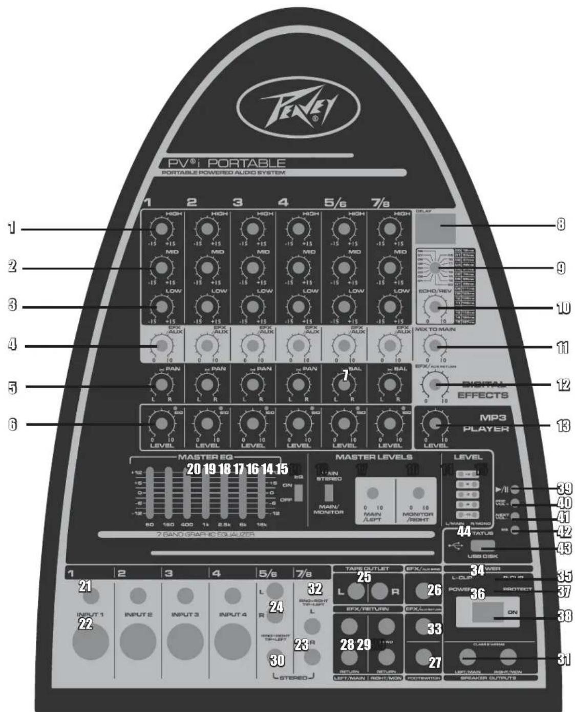
CONTROL FUNCTIONS
1) HIGH - Adjusts the relative level of the high frequency content. Rotating the knob counterclockwise decreases the high frequency response. Rotating the knob clockwise increases the high frequency response. When the EQ controls are set at their middle position, the channel frequency response is "flat" with no frequencies increased or decreased.
2) MID - Adjusts the relative level of the mid frequency content. Rotating the knob counterclockwise decreases the mid frequency response. Rotating the knob clockwise increases the mid frequency response. When the EQ controls are set at their middle position, the channel frequency response is "flat" with no frequencies increased or decreased.
3) LOW - Adjusts the relative level of the low frequency content of the channel. Rotating the knob counterclockwise decreases the low frequency response. Rotating the knob clockwise increases the low frequency response. When the EQ controls are set at their middle position, the channel frequency response is "flat" with no frequencies increased or decreased.
4) EFX/AUX - Adjusts the amount of signal sent to the effects processor, and to the EFX/AUX output jack. Digital effects can be used to enhance the sound quality of any performance where appropriate and desired. In the fully counterclockwise position there is no signal sent to the effects processor or the EFX/AUX jack.
NOTE: When setting the level of the digital delay (or any effect), begin at 0 and slowly increase the level until the desired result is achieved. Digital effects can dramatically enhance the sound of your mix, but too much can have an undesirable effect.
5) PAN - The Pan control features a notched position indicator and adjusts the perceived "position" of the mono signal from the input within the stereo field created by the two speaker cabinets. Full Left or Right rotation of this control sends the signal to that channel only, with no signal sent to the other. The center position sends the same amount of signal to both speakers.
6) LEVEL - Adjusts the volume level of the individual channel. Rotating the knob clockwise increases the respective channel's contribution to the "Main Out" mix, while rotating it counterclockwise decreases the volume. Adjust this control after the PV® i PORTABLE's master output level has been set.
7) BAL - The Balance control features a notched position indicator and adjusts the perceived "position" of the stereo signal from the corresponding stereo channels (5/6 and 7/8). Unlike the PAN control, which sends a mono signal to a stereo output, the BAL control actually balances the amount of the left and right signal coming from the stereo inputs. The center position sends the same amount of signal to both speakers.
DIGITAL EFFECTS
8) Digital Delay Display
9) Digital Delay Adjustment oo(12ms) to 15(197ms) - This controls the time between the initial signal and the delayed effect. The larger the number (in ms) the longer the time between repeats and the more noticeable the effect will be. Delay is useful for fattening vocals when singing. Start with a small amount and experiment. As with any effect, too much can create undesirable results.
10) Digital Echo Adjustment - This control sets the number of repeats of the delay effect. Turn the knob clockwise for maximum repetitions.
11) MIX TO MAIN - This control sets the amount of delay effect that will enter the main mix. Think of this as the master volume for all signals going to the delay unit, or the amount of delayed signal in the main mix.
12) EFX/AUX Return. Occasionally it might be necessary to use an external effects device OR to send a signal to an alternate source. Generally this signal will come from the EFX/AUX Send output (26) and be returned to the EFX/AUX Return (33). The EFX/AUX return control is the master level control for (33).
MASTER CONTROL
14) & 15) These LEDs monitor the output signal levels of both main outputs. The red LED is illuminated when the internal limiter is engaged to prevent the signal from being clipped (clipping results in distortion and should be avoided). If the Limiter LED flashes continuously or remains on constantly during use, reduce the output levels until they flash only during strong signal peaks.
16) & 17) MASTER VOLUME LEVEL CONTROLS - The Left and Right Master Volume Controls adjust the main output level of the PV® PORTABLE. For the majority of applications, the PVi PORTABLE system should be operated with these controls at their 12 o'clock position. In situations where more volume is required the master controls can provide an additional 6 dB of gain when turned to the right of the center position. Set the system up in the normal manner and adjust levels as necessary. Raise the master volume controls beyond their 1 o'clock position only after increasing the individual channel level controls.
18) MAIN STEREO / MAIN MONITOR - Allows the PVi PORTABLE's power amps to be configured as stereo or main/monitor. In STEREO mode, the system operates as a traditional stereo mixer/amplifier. In the MAIN/MONITOR mode, the channel level controls set the level for the Main mix (LEFT master volume control). The EFX/AUX controls set the individual channel levels for the Monitor (RIGHT master volume control). When the MAIN/MONITOR position is selected, the Pan and Balance controls become inoperative (you have selected a mono setting for the output).
Additionally, the internal digital effect is only sent to the MAIN speaker output. Digital effects are not available to the MONITOR speaker output in this mode. Keep in mind that the effects level sends for the MAIN MIX and the signal level to the MONITOR out are both controlled by the EFX/AUX level control.
NOTE: Due to the dual functionality of the EFX/AUX control in the MAIN/MONITOR mode, it is possible to have an undesirable amount of reverb coming out the main output when attempting to increase the level of the monitor output. Conversely, having the correct amount of effect on a channel may result in the level to the monitor being incorrect. If independent monitor/effects controls become mandatory consider upgrading to the Escort 5000 or Escort 6000 portable P.A. system.
19) EQ ON/OFF CONTROL - Inserts EQ (20) into the main signal path. Use this switch to compare the sound of the main mix with and without the EQ. This comparison will help "dial in" the right amount of EQ.
20) MASTER EQ CONTROL - These sliders control the overall EQ of the main mix. Use these controls to compensate for the sound of the room. As with all EQ, use sparingly. Increasing any frequency band too much can cause feedback, and decreasing any frequency band dramatically can cause muffled and unintelligible audio output.
NOTE: Be sure to start out with all EQ sliders set at 0. Adjust up or down slowly and slightly to achieve desired results. It can help to choose a familiar prerecorded track to play through the system while making these adjustments.
MIC/LINE STEREO INPUTS
22) MIC INPUT JACK - These three-pin XLR balanced female connectors are designed to connect to, and receive signals from, low impedance microphones.
NOTE: We recommend the PVi 100 microphone (item number oo577800) or the PVi 2 microphone (item number 0049636).
21) LINE INPUT JACK - These 1/4 balanced input jacks are suited for use with items having line level outputs such as high impedance microphones, keyboards, drum machines, outboard effects, etc. It accepts both balanced and unbalanced cables.
23) & 32) STEREO INPUTS - Stereo phono 1/8 TRS input jack and 1/4 TRS jacks (wired for Tip=Left, Ring=Right and Sleeve=Ground, the standard format of commercially available cables) designed for use with a portable MP3 player, DVD player, or any other stereo source.
Note: These connectors are set at a constant "line level."
24) & 30) STEREO INPUTS - Stereo phono (RCA) input jacks and 1/4 TRS jacks (wired for Tip=Left, Ring=Right and Sleeve=Ground, the standard format of commercially available cables) designed for use with a tape player, DVD player, or any other stereo source.
Note: These connectors are set at a constant "line level."
25) STEREO OUT - The Tape Output RCA jacks provide a mix output that is independent of the Master Level controls. Connect these to the inputs of a recording device, such as a cassette or DAT recorder, to record your event. Changes made during the performance to the input level controls, channel EQ, and reverb controls will be heard in the Tape Out mix. Changes made to the master level controls will not effect the level of the recording. Adjust recording levels according to the instructions on your recording device.
26) EFX / AUX SEND - Although the PV ® i PORTABLE is already equipped with onboard digital effects, an external effects processor can be incorporated into the PVi PORTABLE's signal flow. This 1/4 output jack is designed to send the signal from the EFX/LEVEL control to an external device. The signal can then be routed back to the PVi PORTABLE via the EFX/AUX Return input (33) and controlled by EFX/AUX level control (12).
27) FOOTSWITCH - Connect an optional ON/OFF, 1/4 jack footswitch to this input in order to mute the digital effects when the switch is depressed.
Optional accessory: Peavey Push ON/OFF Button Switch (item number 03051000).
28) & 29) AMPLIFIER SEND / RETURN JACKS - Each channel of the power amplifier has a Send and Return jack. These jacks provide a point to insert an equalizer or other processor into the sound system.
31) SPEAKER OUTPUTS - These are speaker level (powered) output jacks designed to feed each of your PVi PORTABLE speaker enclosures. Use the enclosed cables (or other speaker cables) to connect the PVi PORTABLE's speakers to the power tower.
WARNING: These are powered speaker outputs. Plugging anything other than the appropriate speakers into these outputs could damage the PVi PORTABLE and/or any other device not design to accept a powered output.
33) EFX/AUX RETURN - Plug in your external effects signal processor's output signal here. This 1/4 input stereo jack is designed to accept signals from an external effects unit. This input can also be used as an additional stereo input.
38) POWER SWITCH - Turns the AC power ON and OFF. When the switch is in the OFF position, the PVi PORTABLE is completely shut down.
36) POWER LED INDICATOR - This LED illuminates when the power is turned ON.
37) PROTECT LED INDICATOR - This LED illuminates if the power sound system output connection is shorted or the load impedance is too low.
MP3 PLAYER
Using the MP3 player is simple. Just place the MP3 files on a USB flash memory stick in the root directory, and the PVi PORTABLE will automatically recognize the tracks and begin playing them when plugged into the USB input.
Note: Every attempt has been made to ensure the PVi PORTABLE's USB is compatible with MOST USB flash memory devices, but we cannot ensure it will be compatible with all. If you experience problems with the USB MP3 player, the first step is to try another USB flash memory device.
39) Play and Pause button.
40) Press button for the previous track. Hold button to increase volume.
41) Press button for the next track. Hold button to decrease volume.
42) EQ adjustment. Press this button to change the automatic EQ setting for the USB MP3 player.

43) USB flash disk port for USB disk with MP3 files.
44) LED indicator showing the working status of the USB port.
13) MP3 Level - MP3 input level adjustment; essentially the master volume for the MP3 player.
REAR PANEL
CONNECTOR/LINE CORD - The PV ® i PORTABLE is equipped with a grounding-type IEC supply cord to reduce the possibility of shock hazard. Be sure to connect it to a grounded AC receptacle.
DO NOT ALTER THE AC PLUG.
The power mains (AC) fuse and fuse holder are under the IEC (power cord) socket. Replacement fuses must be of the same rating (6A 250V) and size as originally equipped. To replace a blown fuse, remove the IEC power cord, pull out the fuse holder and find the spare fuse inside.
REAR STORAGE COMPARTMENT
A small storage compartment can be found on the rear of the PVi PORTABLE. To access this compartment, simply lift the latch and pull open the storage door. This compartment is ideal for storing cables, microphones and other accessories.
SETUP & CONNECTIONS
Before turning on the Power, please read and heed the safety warnings in front of manual.
It is important to establish a routine for connecting and powering up your sound system. Provided you have a properly grounded AC outlet or outlet strip with sufficient power handling capacity, plug all sound system equipment into the same outlet or strip. This will enhance system safety and performance. Ensure that the AC circuit is capable of handling the peak power demands of your system. Consult a qualified electrician if in doubt.
WHEN SETTING UP BE SURE TO FOLLOW THESE SIMPLE GUIDELINES:
- First, turn all channel Level and EFX/AUX controls to their fully counterclockwise (OFF) positions. Next, place all graphic EQ sliders in the middle position (o position), and all Pan and Master controls at 12 o'clock in their center-notched positions.
- Next, connect each speaker cable to the appropriate Left & Right Speaker outputs on the front lower right of the main mixing console.
- Connect all microphones, tape decks, keyboards, etc., into the appropriate inputs.
- Finally, check the local voltage and set the voltage selector switch located adjacent to the power input socket on the rear of the mixer amplifier to the appropriate operating range. (See Safety Precautions) Plug the power cable into the IEC (power cord) socket and to a properly grounded 3-wire AC power outlet.

POWERING UP
Turn the Power Switch to the ON position. The Power LED will illuminate green and the system will turn on. If other powered equipment is to be attached to the system, it is always advisable to turn on your PV ® i PORTABLE last. This way any transient spikes and thumps caused by other equipment will not be amplified and sent to your system speakers.
For the same reason, it is advisable to turn off your PVi PORTABLE system first, before turning off attached equipment.
Should the Power LED not illuminate when the power switch is operated, check your power connections and retry. Should the Power LED still fail to illuminate after you have confirmed the power connections, disconnect all cables and check the PVi PORTABLE fuse. Be sure to replace any blown fuses with fuses of the correct value.
Reconnect the power and speaker cables and turn the rear panel power switch ON.
Reset the system by turning on the Power switch. If the Power LED illuminates red, the system is indicating a thermal protect mode or cooling problem. Be sure there isn't anything blocking the air intakes on the rear of the main mixing console.
Turn Power off and wait for a few minutes, allowing heat to dissipate and the PVi PORTABLE to reset itself. If after doing so the Power LED continues to glow red, this indicates a fault with your system and you should consult an authorized Peavey service center.
If no audio is present in one of the speakers, check to see if your control settings are correct. Next, unplug the cable from your working speaker and reconnect it to the other speaker. If the second speaker works, this indicates that the first cable is bad, and should be repaired or replaced.
SETUP SYSTEM VOLUME & LEVELS
To set system volume and operating levels, be sure to follow these simple setup guidelines:
- First, slowly raise the Left and Right Master volume controls to their 12 o'clock notched positions.
2.Use a microphone (or other source) in the same position as it will be used on stage and in the manner in which it will be used for the event. Slowly bring up the appropriate channel input level control, listening for the onset of feedback or until the desired level is reached. - The easiest way to set the master EQ sections is to play a prerecorded track through the system while adjusting the EQ. Be mindful that while enhanced bass may sound good with pre-recorded tracks, it may cause unwanted low-end feedback and rumbling during a live performance.
- Place the speakers in a manner that will allow them to project to the majority of your audience while making sure not to aim them at open microphones. Anytime a microphone can "hear" the sound of the speakers, it will cause feedback. Make sure your speakers are well forward of any open microphone.
- Optional speaker stands can be purchased from your local Peavey dealer.

Features and specifications are subject to change without notice.
Peavey Electronics Corporation dot 5022 Hartley Peavey Drive dot Meridian, MS dot 39305
(601) 483-5365 • FAX (601) 486-1278 • www.peavey.com • EXoo0163 • ©2012
Espanol
PV®i PORTÁTIL
SISTEMA DE AUDIO ELECTRICO PORTÁTIL
Effective Date: 09/15/2010
What This Warranty Covers
Your Peavey Warranty covers defects in material and workmanship in Peavey products purchased and serviced in the U.S.A. and Canada.
What This Warranty Does Not Cover
The Warranty does not cover: (1) damage caused by accident, misuse, abuse, improper installation or operation, rental, product modification or neglect; (2) damage occurring during shipment; (3) damage caused by repair or service performed by persons not authorized by Peavey; (4) products on which the serial number has been altered, defaced or removed; (5) products not purchased from an Authorized Peavey Dealer.
Who This Warranty Protects
This Warranty protects only the original purchaser of the product.
How Long This Warranty Lasts
The Warranty begins on the date of purchase by the original retail purchaser. The duration of the Warranty is as follows:
| Product Category Duration | |
| Guitars/Basses, Amplifiers, Preamplifiers, Mixers, Electronic Crossovers and Equalizers 2 years * (+3 years) | |
| Drums 2 years * (+1 year) | |
| Enclosures 3 years * (+2 years) | |
| Digital Effect Devices and Keyboards and MIDI Controllers 1 years * (+1 year) | |
| Microphones 2 years | |
| Speaker Components 1 year(incl. Speakers, Baskets, Drivers, Diaphragm Replacement Kits and Passive Crossovers) | |
| Tubes and Meters | 90 Days |
| Cables Limited Lifetime | |
| AmpKit Link, Xport, Rockmaster Series, Strum'n Fun, RetroFire, GT & BT Series Amps | 1 year |
[+ Denotes additional Warranty period applicable if optional Warranty Registration Card is completed and returned to Peavey by original retail purchaser within 90 days of purchase.]
What Peavey Will Do
We will repair or replace (at Peavey's discretion) products covered by Warranty at no charge for labor or materials. If the product or component must be shipped to Peavey for Warranty service, the consumer must pay initial shipping charges. If the repairs are covered by Warranty, Peavey will pay the return shipping charges.
How To Get Warranty Service
(1) Take the defective item and your sales receipt or other proof of date of purchase to your Authorized Peavey Dealer or Authorized Peavey Service Center.
OR
(2) Ship the defective item, prepaid, to Peavey Electronics Corporation, International Service Center, 412 Highway 11 & 80 East, Meridian, MS 39301. Include a detailed description of the problem, together with a copy of your sales receipt or other proof of date of purchase as evidence of Warranty coverage. Also provide a complete return address.
Limitation of Implied Warranties
ANY IMPLIED WARRANTY, INCLUDING WARRANTY OF MERCHANTABILITY AND FITNESS FOR A PARTICULAR PURPOSE, ARE LIMITED IN DURATION TO THE LENGTH OF THIS WARRANTY.
Some states do not allow limitations on how long an implied Warranty lasts, so the above limitation may not apply to you.
Exclusions of Damages
PEAVEY'S LIABILITY FOR ANY DEFECTIVE PRODUCT IS LIMITED TO THE REPAIR OR REPLACEMENT OF THE PRODUCT, AT PEAVEY'S OPTION. IF WE ELECT TO REPLACE THE PRODUCT, THE REPLACEMENT MAY BE A RECONDITIONED UNIT. PEAVEY SHALL NOT BE LIABLE FOR DAMAGES BASED ON INCONVENIENCE, LOSS OF USE, LOST PROFITS, LOST SAVINGS, DAMAGE TO ANY OTHER EQUIPMENT OR OTHER ITEMS AT THE SITE OF USE, OR ANY OTHER DAMAGES WHETHER INCIDENTAL, CONSEQUENTIAL OR OTHERWISE, EVEN IF PEAVEY HAS BEEN ADVISED OF THE POSSIBILITY OF SUCH DAMAGES.
Some states do not allow the exclusion or limitation of incidental or consequential damages, so the above limitation may not apply to you.
This Warranty gives you specific legal rights, and you may also have other rights which vary from state to state.
If you have any questions about this Warranty or services received or if you need assistance in locating an Authorized Service Center, please contact the Peavey International Service Center at (601) 483-5365.
Optional Product Extended Warranty Registration
Give us some information and put your extended warranty into effect!
Please take a few minutes to fill out this information/survey sheet to help us get to know and serve you better.
To save time, submit your warranty registration online at www.peavey.com/support/warrantyregistration
1.
First Name
Initial
Last Name
Street Address
City
State/Province
Postal Code
( )
Telephone Number
E-mail Address
(
Fax Number
Date of Birth
Gender
M
2.

Model
8-Digit Serial Number
Date of Purchase
Price Paid
3.
Name of store where purchased
City
State
- Top two (2) reasons why you purchased from this store/dealer:
Availability of product
Past favorable experience
Friend/Relative's recommendation
Best price
Store credit card
□Advertised special
Knowledgeable staff
Convenient location
Availability of lessons
□ Received as a gift
Technical instruction
□ Other.
- Where do you most often shop for music and sound products?
Independent retailer
□ Newspaper ads
Mass market retailer
Internet/Web sites
Mail order magazines
□ Other.
- What two (2) factors most influenced your purchase of this product?
Peavey brand name
Product appearance
Craftsmanship
Durability
Features for price
Prior experience with Peavey
Bundled accessories
□ Packaging
Sound quality
□ Other
- How did you learn about this Peavey product? (select best answer)
Magazine review
Teacher's recommendation
Newspaper review
Catalog or flyer
Radio advertisement
Saw in store
□Advertised special
Use by professional
□ Friend/Relative's recommendation
Other
Salesperson's recommendation

-
Which other brands/models did you consider?
-
How would you describe your level of musicianship/technical expertise?
Beginner - Never played or taken less than one (1) year of lessons
Intermediate - One (1) to five (5) years of lessons or playing
Advanced - More than five (5) years of lessons or playing; play professionally
- Education: (select best answer)
High school
Some college
Completed college
Graduate school
- Which best describe your family income? (select best answer)
Under $15,000
□75,000-99,999
□15,000-24,999
□ 100,000 -149,999
□25,000-34,999
Over - $150,000
□35,000-49,999
□50,000-74,999
- Which of the following is your primary source of information on musical products: (select best answer)
Television
□ Mail order catalogs
□ Radio
Direct mail
□Internet
Literature from manufacturer
Newspaper
□ Other
Magazines
- What is your main motivation for buying new equipment?
□ Replacing old product
Impulse
Want new and leading edge
Need for improved performance
equipment
New technology
Fullfill a specific need
Availability of product
Supplement existing products
□ Other
Value
-
Please list your three most frequently visited Web sites.
-
http://
- http://
-
http://
-
In your opinion, what could Peavey do to improve its products and/or service? Please use the space below to tell us your answer.
Thank you for taking the time to fill out our survey! Don't forget to fold and tape (with Peavey address facing out), affix postage stamp and drop in the mail!
8019-20066 m W
80LSxOgO'd
Aeae eae aee
e eae

H
e6eIsod
oeid

- IMPORTANT SAFETY INSTRUCTIONS
- FCC Compliancy Statement
- Responsible Party:
- English
- PV-portABLE PORTABLE POWERED AUDIO SYSTEM
- Features:
- SETUP & USE
- CONTROL FUNCTIONS
- DIGITAL EFFECTS
- MASTER CONTROL
- MIC/LINE STEREO INPUTS
- MP3 PLAYER
- REAR PANEL
- DO NOT ALTER THE AC PLUG.
- REAR STORAGE COMPARTMENT
- SETUP & CONNECTIONS
- WHEN SETTING UP BE SURE TO FOLLOW THESE SIMPLE GUIDELINES:
- POWERING UP
- SETUP SYSTEM VOLUME & LEVELS
- Espanol
- PV®i PORTÁTIL
- SISTEMA DE AUDIO ELECTRICO PORTÁTIL
- What This Warranty Covers
- What This Warranty Does Not Cover
- Who This Warranty Protects
- How Long This Warranty Lasts
- What Peavey Will Do
- How To Get Warranty Service
- Limitation of Implied Warranties
- Exclusions of Damages
- Optional Product Extended Warranty Registration
Brand : PEAVEY
Model : PVi Portable
Category : Sound system