
ICS 4200 - Sound system PEAVEY - Free user manual and instructions
Find the device manual for free ICS 4200 PEAVEY in PDF.
| Product Type | 4-Channel Power Amplifier |
| Brand | PEAVEY |
| Model | ICS 4200 |
| Output Power | 200 Watts RMS per channel (4 Ohms or 70V), 400 Watts in bridge mode (8 Ohms or 140V) |
| Number of Channels | 4 |
| Output Impedance | Low impedance (4 or 8 Ohms) or 70V, selectable by pair (A/B and C/D) |
| Input Connectivity | Detachable EURO connectors, electronically balanced |
| Expansion Modules | Two slots for MMA™ input modules |
| Controls | Detented input level controls on front panel with protective cover |
| Protection | Short circuit, over temperature, SPS™ (clipping with gain reduction) |
| Cooling | Dual-speed fan, forced airflow from rear to front |
| Form Factor | 19-inch rack, 2U (88 mm height) |
| Power Supply | 120 VAC, 60 Hz, IEC connector |
| LED Indicators | Power (green), signal presence (yellow), clip (red) per channel |
| Weight | Approximately 14.5 kg |
| Dimensions (W x H x D) | 483 x 88 x 300 mm |
| Safety | Circuit breaker on front panel, grounding, CLASS 3 wiring required for 140V outputs |
| Recommended Use | Paging systems, multi-zone distribution, professional installations |
| Maintenance and Cleaning | Disconnect before cleaning; use a dry cloth; do not block ventilation grilles |
| Spare Parts and Repairability | MMA modules, EURO connectors, power cord available from authorized Peavey dealer |
Frequently Asked Questions - ICS 4200 PEAVEY
User questions about ICS 4200 PEAVEY
0 question about this device. Answer the ones you know or ask your own.
Ask a new question about this device
Download the instructions for your Sound system in PDF format for free! Find your manual ICS 4200 - PEAVEY and take your electronic device back in hand. On this page are published all the documents necessary for the use of your device. ICS 4200 by PEAVEY.
USER MANUAL ICS 4200 PEAVEY
natural_image
Abstract pattern of intersecting circuit lines and circular markers on a textured background (no text or symbols)
Intended to alert the user to the presence of uninsulated “dangerous voltage” within the product’s enclosure that may be of sufficient magnitude to constitute a risk of electric shock to persons.

Intended to alert the user of the presence of important operating and maintenance (servicing) instructions in the literature accompanying the product.
CAUTION: Risk of electrical shock — DO NOT OPEN!
CAUTION: To reduce the risk of electric shock, do not remove cover. No user serviceable parts inside. Refer servicing to qualified service personnel.
WARNING: To prevent electrical shock or fire hazard, this apparatus should not be exposed to rain or moisture, and objects filled with liquids, such as vases, should not be placed on this apparatus. Before using this apparatus, read the operating guide for further warnings.

WARNING: When using electrical products, basic cautions should always be followed, including the following:
- Read these instructions.
- Keep these instructions.
- Heed all warnings.
- Follow all instructions.
- Do not use this apparatus near water.
- Clean only with a dry cloth.
- Do not block any of the ventilation openings. Install in accordance with manufacturer's instructions.
- Do not install near any heat sources such as radiators, heat registers, stoves or other apparatus (including amplifiers) that produce heat.
- Do not defeat the safety purpose of the polarized or grounding-type plug. A polarized plug has two blades with one wider than the other. A grounding type plug has two blades and a third grounding plug. The wide blade or third prong is provided for your safety. If the provided plug does not fit into your outlet, consult an electrician for replacement of the obsolete outlet.
- Protect the power cord from being walked on or pinched, particularly at plugs, convenience receptacles, and the point they exit from the apparatus.
- Note for UK only: If the colors of the wires in the mains lead of this unit do not correspond with the terminals in your plug, proceed as follows:
a) The wire that is colored green and yellow must be connected to the terminal that is marked by the letter E, the earth symbol, colored green or colored green and yellow.
b) The wire that is colored blue must be connected to the terminal that is marked with the letter N or the color black.
c) The wire that is colored brown must be connected to the terminal that is marked with the letter L or the color red.
-
Only use attachments/accessories provided by the manufacturer.
-
Use only with a cart, stand, tripod, bracket, or table specified by the manufacturer, or sold with the apparatus. When a cart is used, use caution when moving the cart/apparatus combination to avoid injury from tip-over.
- Unplug this apparatus during lightning storms or when unused for long periods of time.
- Refer all servicing to qualified service personnel. Servicing is required when the apparatus has been damaged in any way, such as power-supply cord or plug is damaged, liquid has been spilled or objects have fallen into the apparatus, the apparatus has been exposed to rain or moisture, does not operate normally, or has been dropped.
- Never break off the ground pin. Write for our free booklet “Shock Hazard and Grounding.” Connect only to a power supply of the type marked on the unit adjacent to the power supply cord.
- If this product is to be mounted in an equipment rack, rear support should be provided.
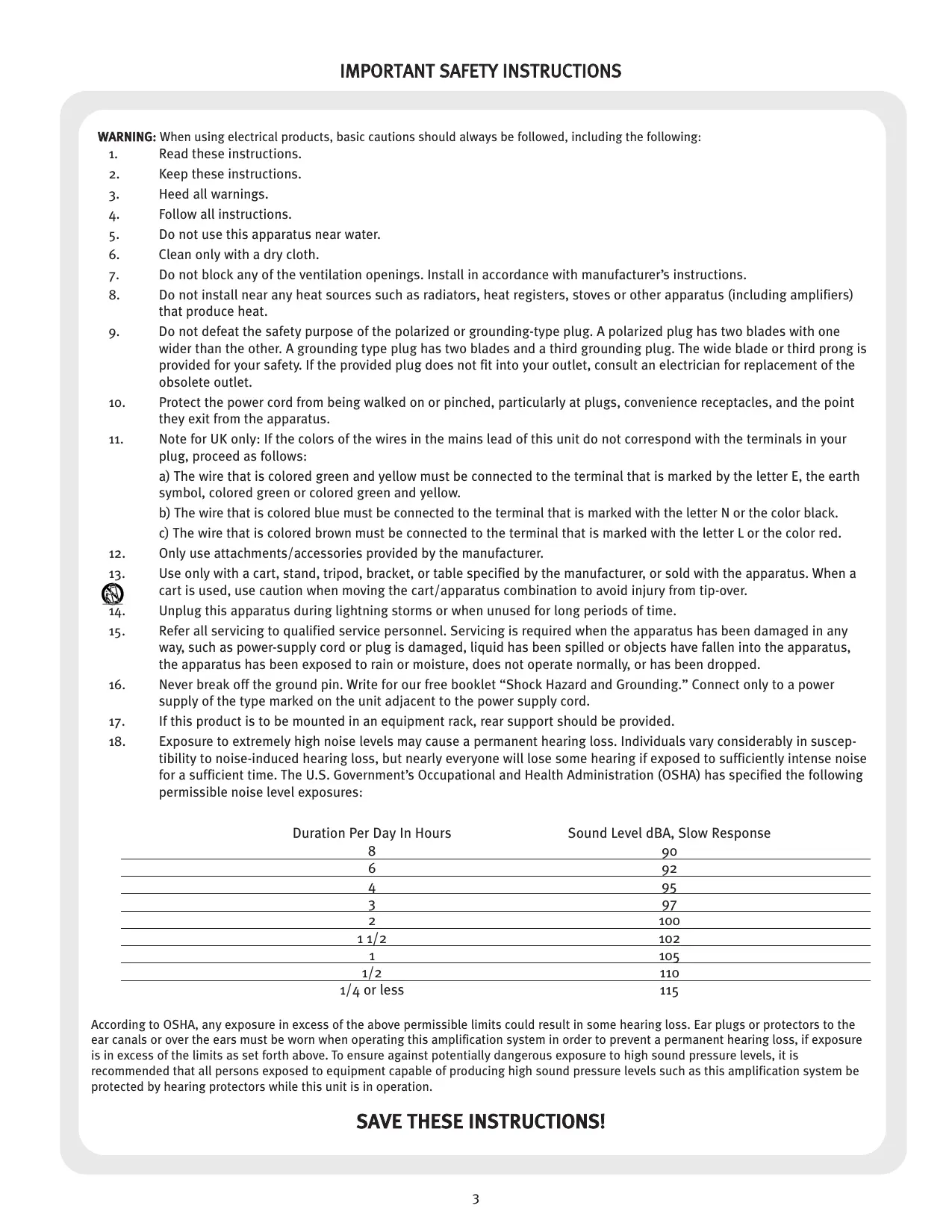
- Exposure to extremely high noise levels may cause a permanent hearing loss. Individuals vary considerably in susceptibility to noise-induced hearing loss, but nearly everyone will lose some hearing if exposed to sufficiently intense noise for a sufficient time. The U.S. Government's Occupational and Health Administration (OSHA) has specified the following permissible noise level exposures:
| Duration Per Day In Hours | Sound Level dBA, Slow Response |
| 8 | 90 |
| 6 | 92 |
| 4 | 95 |
| 3 | 97 |
| 2 | 100 |
| 112 | 102 |
| 1 | 105 |
| 1/2 | 110 |
| 1/4 or less | 115 |
According to OSHA, any exposure in excess of the above permissible limits could result in some hearing loss. Ear plugs or protectors to the ear canals or over the ears must be worn when operating this amplification system in order to prevent a permanent hearing loss, if exposure is in excess of the limits as set forth above. To ensure against potentially dangerous exposure to high sound pressure levels, it is recommended that all persons exposed to equipment capable of producing high sound pressure levels such as this amplification system be protected by hearing protectors while this unit is in operation.
SAVE THESE INSTRUCTIONS!
ENGLISH
ICS™ 4200 Power Amplifier
The ICS ™ 4200 is a 4-channel power amplifier designed for years of reliable, flawless operation under rigorous use. This amplifier offers the sonic superiority and unsurpassed reliability for which Peavey is famous, while remaining surprisingly compact. Advanced technology and extensive protection circuitry allow operation with greater efficiency into difficult loads and power conditions. The SPS ™ (Speaker Protection System) circuitry ensures trouble-free operation into loads as low as 4 Ohms. This amplifier is ideal for paging systems, foreground and background music distribution as well as other applications that may require multiple zones. Each channel delivers 200 Watts of power!
Although the ICS 4200 amplifier is quite simple to operate and is housed in ultra-strong steel chassis, improper use can be dangerous. This amplifier is very high-powered and can put out high voltages and sizable currents. Always use safe operating techniques when operating this amplifier.
• 4-channel power amp system—200 WATTS RMS per channel
- Low Z (4 or 8 Ohms) or 70 V output—selectable in 2-channel pairs
• Dedicated Euro-type, electronically-balanced input connectors
- Two input ports: accepts MMA™ plug-in input modules—dip-switch selectable to any channel
- Front panel detented level controls—with security cover
- Front panel AC power switch/circuit breaker
- Short circuit and thermal protection circuitry
- Rugged, rack-mount design—2U rack space
• 2-speed fan-cooled design
- Front panel LED indicators per channel: signal & clip
Unpacking
Upon unpacking, inspect the amplifier. If you find any damage, notify your supplier immediately. Only the consignee may institute a claim with the carrier for damage incurred during shipping. Be sure to save the carton and all packing materials. Should you ever need to ship the unit back to Peavey Electronics, one of its offices, service centers, or the supplier, use only the original factory packing. If the shipping carton is unavailable, contact Peavey to obtain a replacement.
Mounting
The ICS 4200 amplifier will mount in standard 19" racks.
Security Cover
A security cover is provided to prevent inadvertent level adjustments. It is designed to permit monitoring of the various LEDs without removal. To remove the cover, simply remove the Phillips-head mounting screw.
Cooling Requirements
The ICS 4200 amplifier uses a forced-air cooling system to maintain a low, even operating temperature. Air is drawn into the amplifier via a fan located in the back of the unit and courses through the cooling fins of the tunnel-configured channel heat sinks. The air then exhausts through the front panel slots. If the heat sinks get too hot, a sensing circuit will activate the protective muting system to protect the amplifier. When the internal temperature reaches a safe level, the amplifier will automatically return to normal operation. It is important that both the front and rear of the unit have enough space to allow the cooling air to enter and escape. If the amp is rack mounted, do not use doors or covers on the front of the rack; the intake air must flow without resistance. If you are using racks with closed backs, make sure that there is one (1) standard rack space opening for every three mounted power amplifiers. If not rack-mounted, allow 6" of clearance on all sides.

Operating Precautions
Make sure the mains voltage is correct and is the same as that printed on the rear of the amplifier. Damage caused by connecting the amplifier to improper AC voltage is not covered by any warranty.
Note: Always turn off and disconnect the amplifier from mains voltage before making audio connections. Also, as an extra precaution, have the attenuators turned down during power-up.
It is always a good idea to have the gain controls turned down during power-up to prevent speaker damage if there is a high signal level at the inputs. Whether you buy or make them, use good-quality connections, input cables and speaker cables, along with good soldering technique, to ensure trouble-free operation. Most intermittent problems are caused by faulty cables.
Consult the Wire Gauge Chart (below) to determine proper gauges for different load impedances and cable lengths. Remember that cable impedance robs amplifier power in two ways: power lost directly to resistance ( I2R loss), and by raising the total load impedance.
WIRE GAUGE CHART
| Cable Length(In Feet) | Stranded Wire Gauge(AWG) | Power Loss into8 Ohms (%) | Power Loss into4 Ohms (%) | Power Loss into2 Ohms (%) |
| 5 | 18 | .79 | 1.58 | 3.16 |
| 16 | .50 | 1.00 | 2.00 | |
| 14 | .31 | .62 | 1.24 | |
| 12 | .20 | .40 | .80 | |
| 10 | .125 | .25 | .50 | |
| 10 | 18 | 1.58 | 3.16 | 6.32 |
| 16 | 1.00 | 2.00 | 4.00 | |
| 14 | .62 | 1.25 | 2.50 | |
| 12 | .40 | .80 | 1.60 | |
| 10 | .25 | .50 | 1.00 | |
| 40 | 18 | 8.00 | 12.60 | 25.20 |
| 16 | 4.00 | 8.00 | 1.60 | |
| 14 | 2.50 | 5.00 | 10.00 | |
| 12 | 1.60 | 3.20 | 6.40 | |
| 10 | 1.00 | 2.00 | 4.00 | |
| 8 | .625 | 1.25 | 2.50 | |
| 80 | 16 | 8.00 | 16.00 | 32.00 |
| 14 | 5.00 | 10.00 | 20.00 | |
| 12 | 3.20 | 6.40 | 12.80 | |
| 10 | 2.00 | 4.00 | 8.00 |
Front Panel

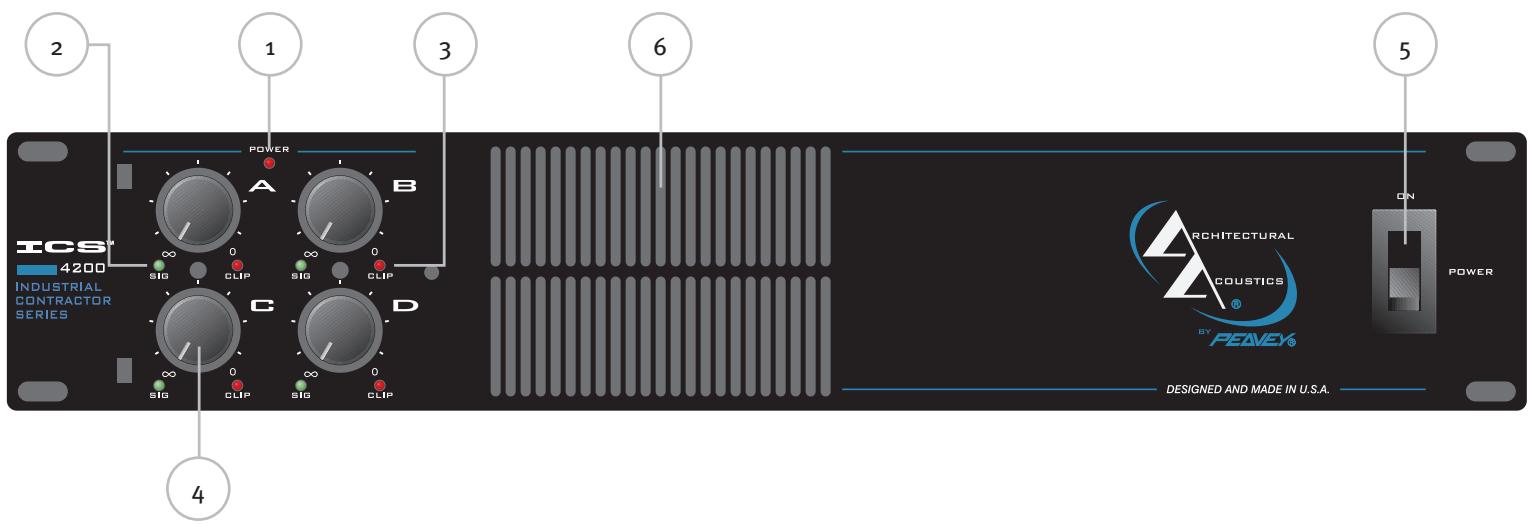
(1) Power Indicator
The green LED indicates AC power is supplied to the unit, the power switch is on and the unit is functional with no faults. If the amplifier has a thermal fault condition, this LED will not illuminate.
(2) Signal Indicators
Yellow LEDs indicate signal presence at that specific channel output. Identical on each channel.
(3) Clip (SPS™) Indicators
Any time a channel is driven into hard, continuous clipping, the SPS circuit will automatically reduce the channel gain to a level just slightly into clipping, guarding the speakers against the damaging high power continuous square waves that may be produced. Situations that may activate the SPS circuit include uncontrolled feedback, oscillations, or an improper equipment setting or malfunction upstream from the amplifier. On the ICS ™ 4200, normal program transients will not trigger SPS; only steady, excessive clipping will. The LEDs will illuminate red when SPS circuitry is active for each channel amplifier.
(4) Input Level Controls
These controls adjust the signal level to the power amplifier inputs. Maximum input sensitivity is achieved at the fully clockwise setting. These controls are detented to allow the input sensitivity of the channels to be closely matched. This is essential in the bridged-output mode. See MODE CONFIGURATION below.
(5) AC Power Switch/Circuit Breaker
The ICS ™ 4200 amplifier has a combination AC switch/circuit breaker on the front panel. If the switch shuts off during normal use, push it back to the ON position once. If it will not stay on, the amplifier needs servicing.
Warning: The power switch does not break both sides of the line and under certain conditions, hazardous energy can be present when the switch is in the OFF position.
(6) Cooling Air Vent
The ICS 4200 is designed to operate under extreme conditions. Part of this design includes the air vents visible from the front of the unit. These openings should never be blocked.
Rear Panel


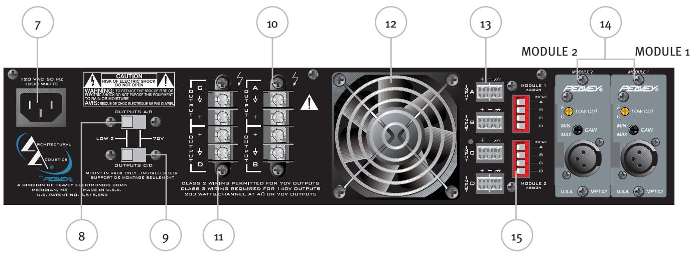
(7) AC Mains Power Receptacle
This is a standard IEC power connector. An AC mains cord having the appropriate AC plug and ratings for the intended operating voltage is included in the carton. The mains cord should be connected to the amplifier before connecting to a suitable AC outlet.
AC Mains Cord
The mains cord supplied with the unit is heavy-duty, 3-conductor type with a conventional 120 VAC plug with ground pin. Never break off the ground pin on any equipment. It is provided for your safety. If the outlet used does not have a ground pin, a suitable grounding adapter should be used and the third wire should be properly grounded.
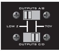
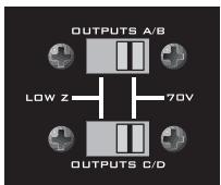
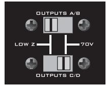
(8) Channel A/B Output Selector (Low Z or 70 Volt)
This slide switch allows channels A and B of this amp to be configured for either conventional Low Z or to a 70 Volt distribution loudspeaker system.
(9) Channel C/D Output Selector (Low Z or 70 Volt)
This slide switch allows channels C and D of this amp to be configured for either conventional Low Z or to a 70 Volt distribution loudspeaker system.
(10) Channel A/B Outputs
The outputs are screw-terminal type for channels A and B. Connect the loudspeaker system to the respective positive and ground terminals.
(11) Channel C/D Outputs
The outputs are screw-terminal type for channels C and D. Connect the loudspeaker system to the respective positive and ground terminals.
(12) Fan Grill
A two-speed DC fan supplies cool air to the amplifier. This intake should never be blocked. The fan automatically switches to high-speed when the unit requires additional cooling. When the amplifier is relatively cool and at idle, the fan should operate at low speed. The fan should never stop unless the amplifier is switched off or the AC mains power source is interrupted.
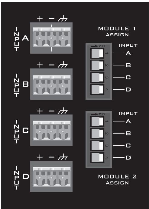
(13) Channel Inputs
These removable “Euro” connectors allow for electronically-balanced input signals to be connected to the system. Each input has a sensitivity of 1.4 V and low-end roll-off at 60 Hz.
(14) MMA™ Plug-in Module Ports
Accepts two optional MMA ™ plug-in input modules. These modules should be selected by installation requirements. For details, refer to the individual MMA Module Operation Guide.
Caution: MMA Plug-in Modules should not be inserted or removed while the amplifier is turned on.
(15) Module Output to Channel Selectors
These DIP switches are used to route the outputs of the respective Module to the desired amplifier channel(s). For a specific channel selection the DIP switch must be switched.
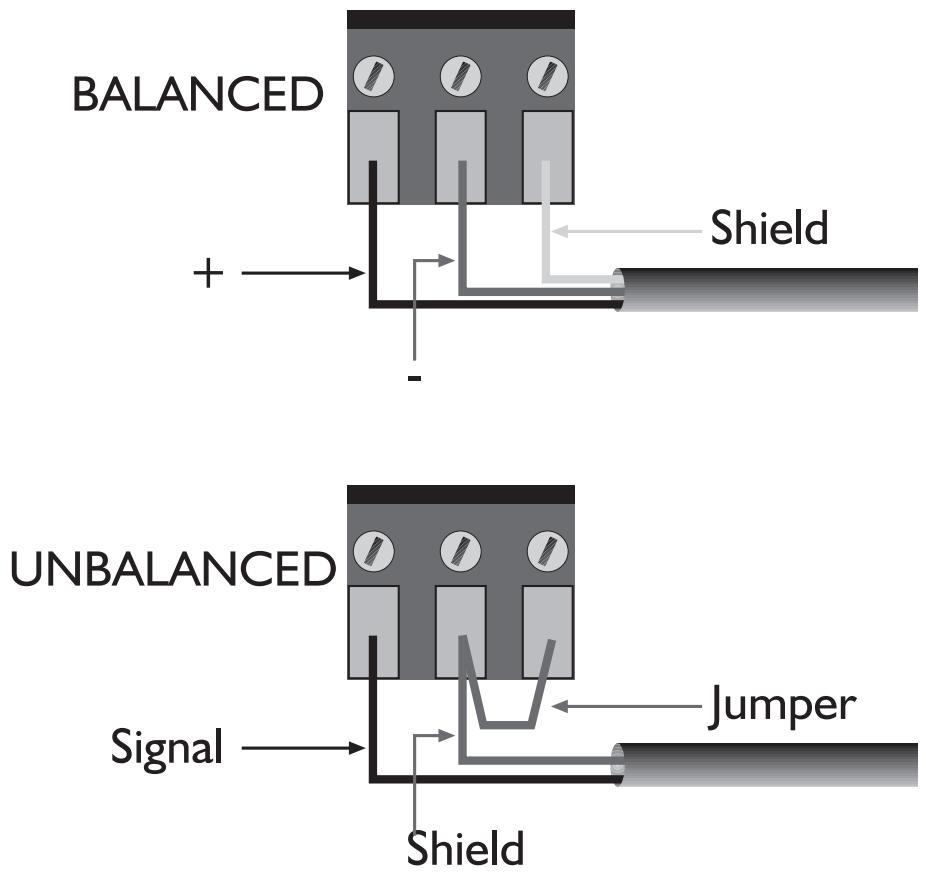
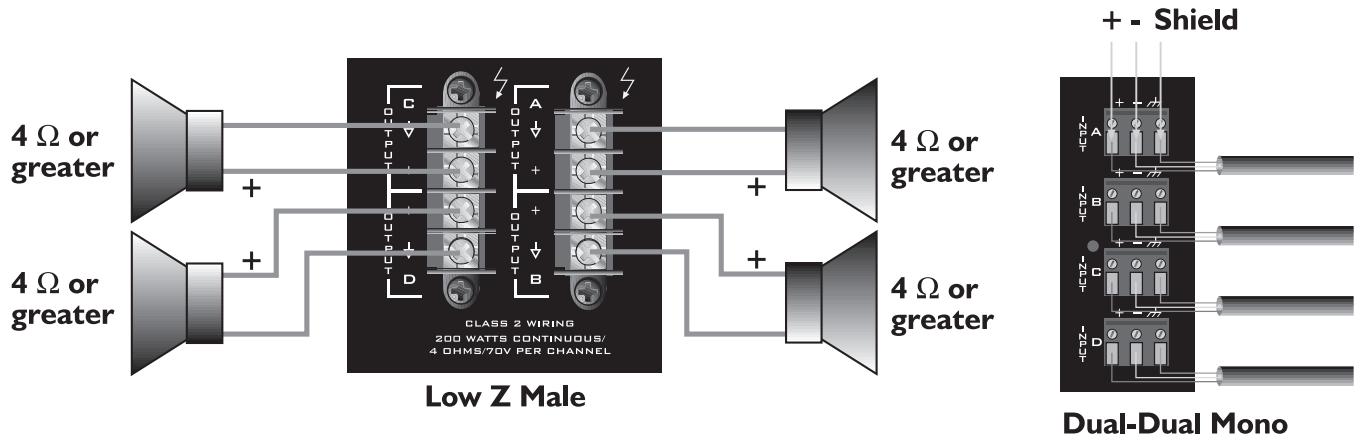
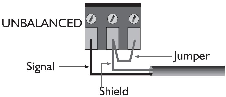
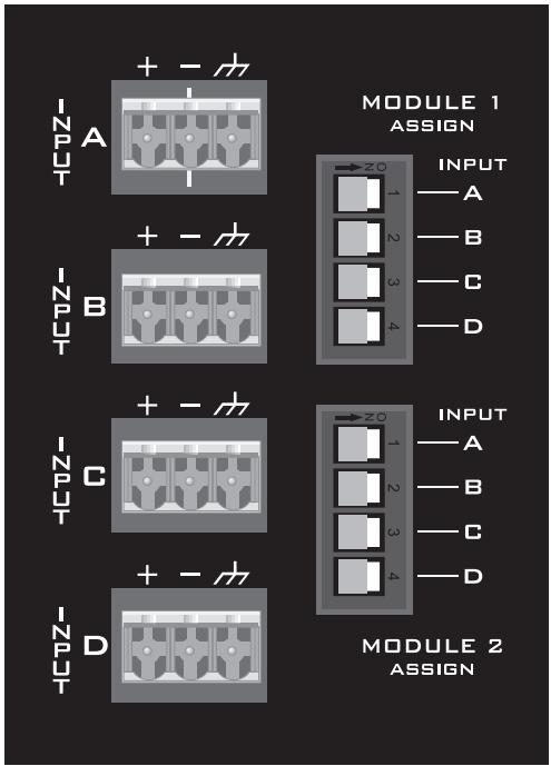
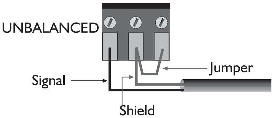
Input Connections
The Euro-style connectors are wired as: Pin 1 is positive; Pin 2 is negative; and Pin 3 is chassis ground. Normally balanced inputs are wired using two-conductor shielded cable as shown in the following diagram. For un-balanced (single-ended) inputs, the single conductor is wired to Pin 1; and the shield is connected to Pins 2 & 3 as shown in the following diagram.
Input Modules
DIP Switch Settings
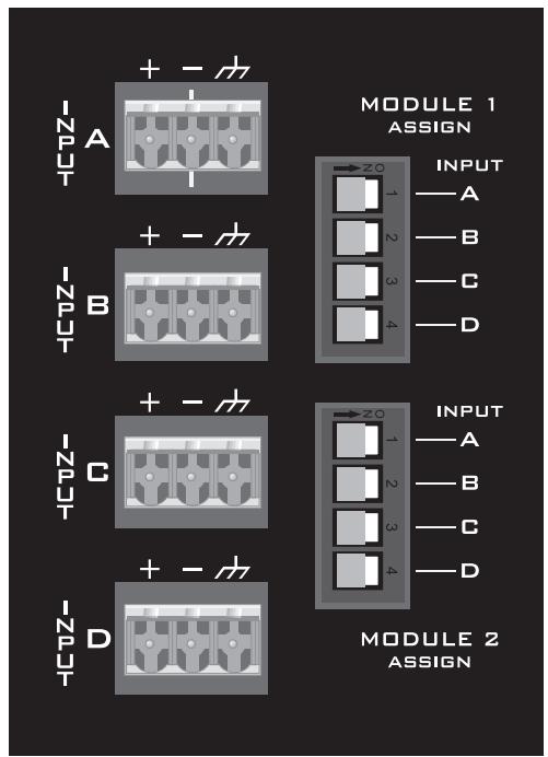

Level Controls
The output of each module may be assigned to any channel and in any combination of channels. To assign the output of Module 1 to an amplifier channel(s), simply slide the appropriate switch in the upper bank of switches to the ON position (right). Likewise, to assign the output of Module 2 to an amplifier channel(s), slide the appropriate switch in the lower bank of switches to the ON position (right).
When selecting these switches, caution should be taken to ensure the front panel channel level controls are fully counter-clockwise or the amplifier is powered off. This will help prevent any damage to the loudspeaker system if there are high signal levels at the module inputs.
Caution: MMA™ plug-in modules should not be inserted or removed while amplifier is turned on.
Attenuation in dB
The signal level for each input can be attenuated by adjusting the 21-detent front panel level control. The table at right shows the amount of attenuation in dB for each detent.
Note: Attenuation amounts shown may vary ±10%.
| DETENT | ATTENUATION |
| 0 (fully CCW) | -85.0 |
| 1 | -58.0 |
| 2 | -35.0 |
| 3 | -26.0 |
| 4 | -20.0 |
| 5 | -16.0 |
| 6 | -13.0 |
| 7 | -11.5 |
| 8 | -9.5 |
| 9 | -8.5 |
| 10 | -7.0 |
| 11 | -5.8 |
| 12 | -4.7 |
| 13 | -3.9 |
| 14 | -3.0 |
| 15 | -2.2 |
| 16 | -1.4 |
| 17 | -0.65 |
| 18 | -0.25 |
| 19 | -0.03 |
| 20 (fully CW) | 0.00 |
MODE CONFIGURATIONS
The inputs are configurable for three modes of operation and the outputs for two modes of operation.
Input Modes
The channel inputs can be connected in three different ways to achieve the following modes of operation.
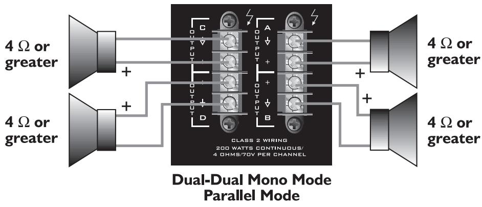
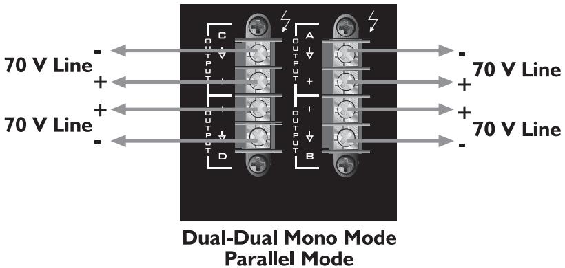
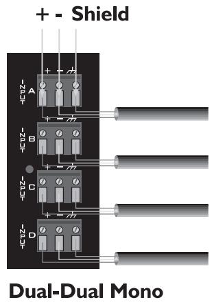
Dual-Dual Mono Mode
For Dual-Dual Mono operation, connect the inputs as shown below. In this mode, all four channels operate independently of each other with their input attenuators controlling each respective input level. As a result, a signal at the input of Channel A produces an amplified signal at the output of Channel A. Likewise, a signal at the input of Channel B produces an amplified signal at the output of Channel B, and so on. The loudspeaker load is connected to the amplifier output terminals matching the positive loudspeaker connection with the positive output terminal. Furthermore, the negative loudspeaker connection is matched with the negative output terminal. See OUTPUT MODES below.

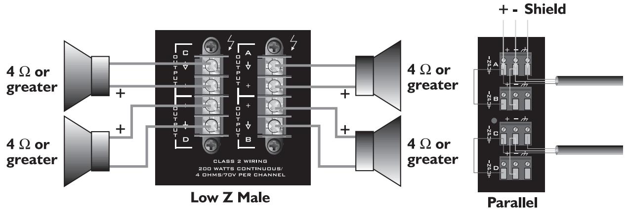
Parallel Mode
The figure below shows an example of parallel input connections. This mode sends the same signal to each of the connected input channels without using a Y-cable. For example, connect the input signal to Channel A input connector. Then, connect jumper wires from the positive (+) and negative (-) terminals of the Channel A input connectors to the respective input terminals of Channel B. Both channels then share the Channel A input signal but will operate independently. The loudspeaker loads are connected as in the Dual-Dual Mono mode. See OUTPUT MODES below.
Any combination of parallel inputs may be configured in this mode, however, be aware of the output mode settings.


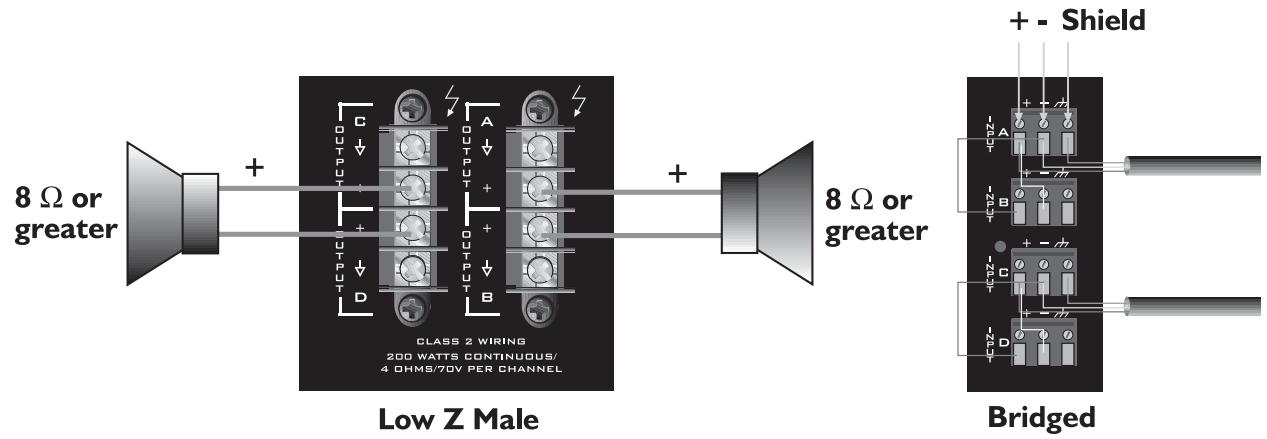
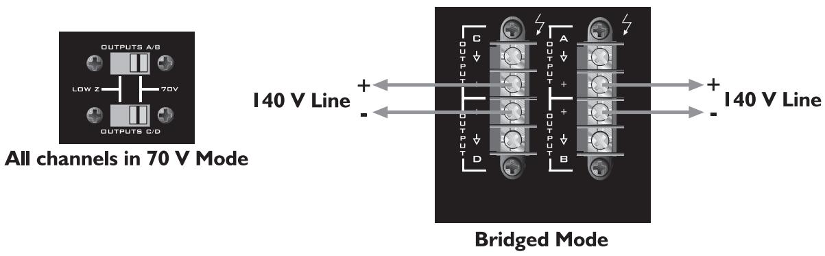
Bridged Mode
A pair of amplifiers may be bridged together to make a single output with a power rating equal to the sum of both channel power ratings at twice the load rating of a single channel. In other words, bridging two amplifiers rated for 200 Watts into 4 Ohms will produce 400 Watts into 8 Ohms. In Bridged Mode, the channels operate at opposite polarity from each other so that one channel pushes and the other pulls equally. This mode sends the input signal to one channel and the same signal with its polarity reversed to the other channel in the pair (A/B or C/D). For example, connect the input signal to Channel A input connector. Then, connect a jumper wire from the positive (+) terminal of the Channel A input connector to the negative (-) terminal of the Channel B input connector. Likewise, connect a jumper wire from the negative (-) terminal of the Channel A input connector to the positive (+) terminal of the Channel B input connector. (See below.) Both channel level controls (in this example, A & B) MUST be used to control the signal level and both MUST be set at the same position. The input level controls are detented to match these settings precisely.
Note: Due to the unique input topology, the module ports CAN NOT be set up to drive the amplifier in Bridged Mode.
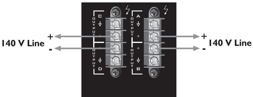
The loudspeaker load is connected only to the designated positive (+) output terminals of the bridged channels. NEVER ground either side of the loudspeaker load cable when the amplifier is in Bridged Mode as both sides are “hot.” If an output patch panel is used, all connections must be isolated from each other and from the panel. In the Low Z output mode, the minimum nominal load impedance in Bridged Mode is 8 Ohms; this is equivalent to driving both bridged channels at 4 Ohms. In the 70 V output mode, the bridged output is 140 V and the minimum load impedance in Bridged Mode is 50 Ohms. Driving loads of lesser impedance may activate the protective muting system. See OUTPUT MODES below.
Note: Regardless of operating modes, NEVER connect the amplifier outputs together.
Caution: Output voltages greater than 120 V RMS are available between the bridged terminals. CLASS 3 wiring must be used in accordance with national and local codes to connect the loudspeaker system.
Warning: The loudspeaker output connections of this amplifier are hazardous when live and present a shock hazard when they are energized. Take the following precautions:
- Do not touch any bare wires that are connected to the loudspeaker output connectors.
- Use insulated loudspeaker cables and touch-proof connectors on the loudspeakers.
- Do not attempt to make connections to the output connectors or the loudspeaker connectors when the amplifier is turned on.
- Double-check all connections and make sure there are no exposed wires or connectors before turning the amplifier on.
- Make sure there are no frayed-cables or wires and that all connections are tight and secure every time before turning the amplifier on.
- External wiring connected to these terminals requires installation by a trained person or the use of ready-made leads or cords.

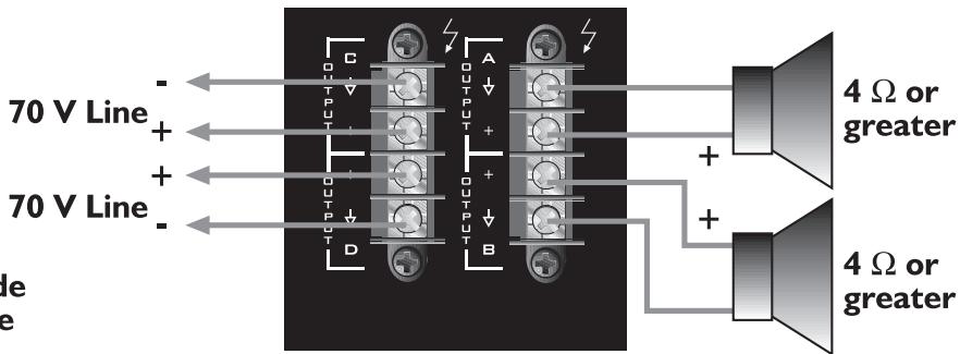
Output Modes
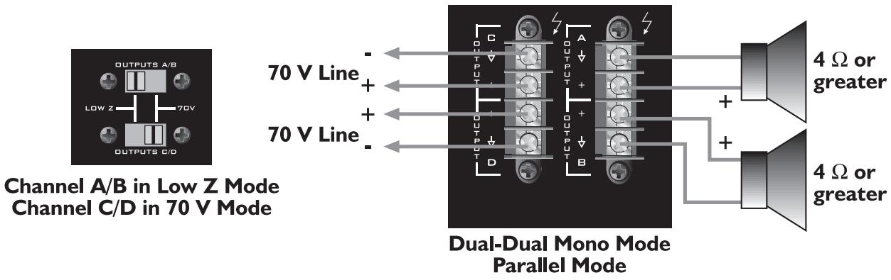
Each channel of the ICS ™ 4200 can drive conventional low-impedance loudspeaker loads ( ≥ 4 Ohms) or a 70 Volt constant-voltage audio distribution system directly. The setting of the output selector switches determines the mode for each pair of outputs. One switch controls Channels A and B and the other switch controls Channels C and D. Single channel selection is not possible. For proper cable selection, see Wire Gauge Chart on page 5 of this manual.
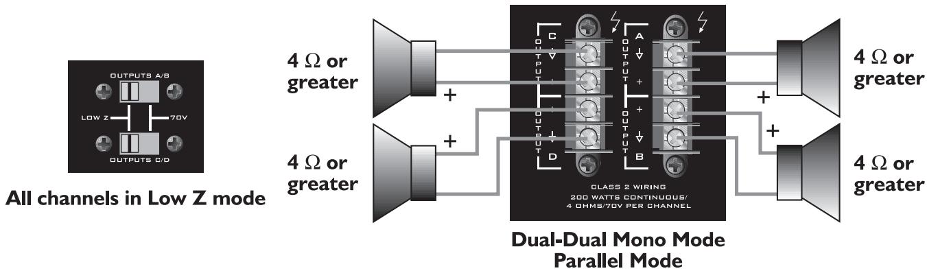
Low Z
This mode allows each output of the channel pair to drive a 4 or 8 Ohm loudspeaker load. Use the Bridged Mode to deliver the power of both channels to a single 8 Ohm load such as a subwoofer. Se INPUT MODES above.
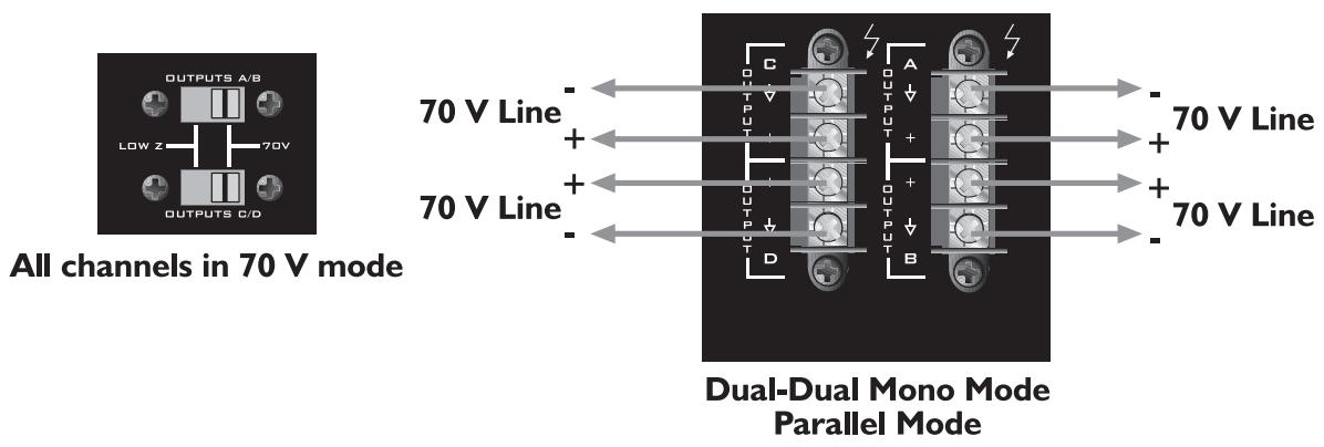
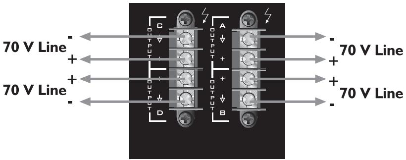
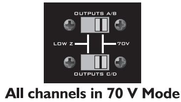
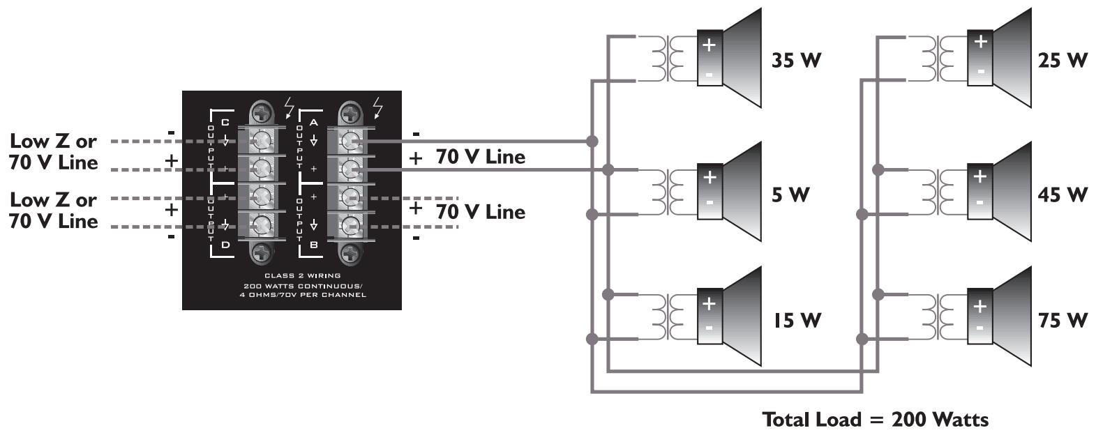
70 V
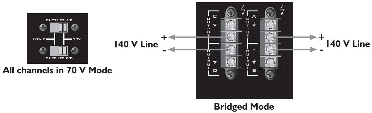
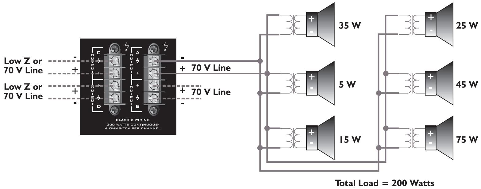
This mode allows each output of the channel pair to directly drive a 70 Volt constant-voltage audio distribution system. Use the Bridged Mode to deliver the power of both channels to a 140 Volt constant-voltage audio distribution system. See INPUT MODES above.
Example of a 70 Volt constant-voltage distribution system
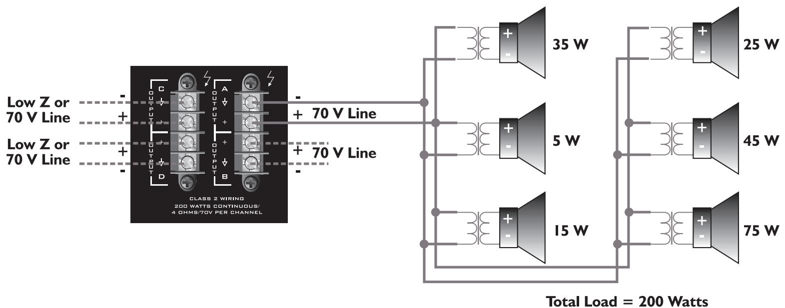

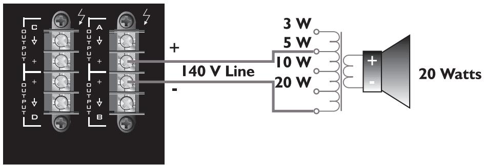
Use of a 70 Volt matching transformer is possible with a 140 Volt system by connecting the tap that is rated for 1/4 power or less of desired 70 Volt tap. For example, a ceiling loudspeaker with a 70 Volt input tapped for 20 Watts is to be used with a 140 Volt constant-voltage system. The 140 Volt system will need to be connected to the 5 Watt tap in order for the loudspeaker to produce 20 Watts. If a 5 Watt tap is not available, use the next lower tap.
Caution: Output voltages greater than 120 Volts RMS are available between the bridged terminals. CLASS 3 wiring must be used in accordance with national and local codes to connect the loudspeaker system.
Bridged Mode
15
flowchart
graph TD
    A["24V"] --> B["MODULE 1"]
    B --> C["MODULE 1 ASSIGN"]
    C --> D["MC1"]
    D --> E["MC2"]
    E --> F["MC3"]
    F --> G["MC4"]
    G --> H["MC5"]
    H --> I["MC6"]
    I --> J["MC7"]
    J --> K["MC8"]
    K --> L["MC9"]
    L --> M["MC10"]
    M --> N["MC11"]
    N --> O["MC12"]
    O --> P["MC13"]
    P --> Q["MC14"]
    Q --> R["MC15"]
    R --> S["MC16"]
    S --> T["MC17"]
    T --> U["MC18"]
    U --> V["MC19"]
    V --> W["MC20"]
    W --> X["MC21"]
    X --> Y["MC22"]
    Y --> Z["MC23"]
    Z --> AA["MC24"]
    AA --> AB["MC25"]
    AB --> AC["MC26"]
    AC --> AD["MC27"]
    AD --> AE["MC28"]
    AE --> AF["MC29"]
    AF --> AG["MC30"]
    AG --> AH["MC31"]
    AH --> AI["MC32"]
    AI --> AJ["MC33"]
    AJ --> AK["MC34"]
    AK --> AL["MC35"]
    AL --> AM["MC36"]
    AM --> AN["MC37"]
    AN --> AO["MC38"]
    AO --> AP["MC39"]
    AP --> AQ["MC40"]
    AQ --> AR["MC41"]
    AR --> AS["MC42"]
    AS --> AT["MC43"]
    AT --> AU["MC44"]
    AU --> AV["MC45"]
    AV --> AW["MC46"]
    AW --> AX["MC47"]
    AX --> AY["MC48"]
    AY --> AZ["MC49"]
    AZ --> BA["MC50"]
    BA --> BB["MC51"]
    BB --> BC["MC52"]
    BC --> BD["MC53"]
    BD --> BE["MC54"]
    BE --> BF["MC55"]
    BF --> BG["MC56"]
    BG --> BH["MC57"]
    BH --> BI["MC58"]
    BI --> BJ["MC59"]
    BJ --> BK["MC60"]
    BK --> BL["MC61"]
    BL --> BM["MC62"]
    BM --> BN["MC63"]
    BN --> BO["MC64"]
    BO --> BP["MC65"]
    BP --> BQ["MC66"]
    BQ --> BR["MC67"]
    BR --> BS["MC68"]
    BS --> BT["MC69"]
    BT --> BU["MC70"]
    BU --> BV["MC71"]
    BV --> BW["MC72"]
    BW --> BX["MC73"]
    BX --> BY["MC74"]
    BY --> BZ["MC75"]
    BZ --> CA["MC76"]
    CA --> CB["MC77"]
    CB --> CC["MC78"]
    CC --> CD["MC79"]
    CD --> CE["MC80"]
    CE --> CF["MC81"]
    CF --> CG["MC82"]
    CG --> CH["MC83"]
    CH --> CI["MC84"]
    CI --> CJ["MC85"]
    CJ --> CK["MC86"]
    CK --> CL["MC87"]
    CL --> CM["MC88"]
    CM --> CN["MC89"]
    CN --> CO["MC90"]
    CO --> CP["MC91"]
    CP --> CQ["MC92"]
    CQ --> CR["MC93"]
    CR --> CS["MC94"]
    CS --> CT["MC95"]
    CT --> CU["MC96"]
    CU --> CV["MC97"]
    CV --> CW["MC98"]
    CW --> CX["MC99"]
    CX --> CY["MC100"]

    subgraph Module 1
        D
        E
        F
        G
        H
        I
        J
        K
        L
        M
        N
        O
        P
        Q
        R
        S
        T
        U
        V
        W
        X
        Y
        Z
        AA
        AB
        AC
        AD
        AE
        AF
        AG
        AH
        AI
        AJ
        AK
        AL
        AM
        AN
        AO
        AP
        AQ
        AR
        AS
        AT
        AU
        AV
        AW
        AX
        AY
        AZ
        BA
        BB
        BC
        BD
        BE
        BF
        BG
        BH
        BI
        BJ
        BK
        BL
        BM
        BN
        BO
        BP
        BPB
        BPc
        BPd
        BPf
        BPg
        BPh
        BPi
        BPj
        BPk
        BPl
        BPm
        BPn
        BPq
        BPqb
        BPqc
        BPqe
        BPqf
        BPqg
        BPqh
        BPqg
        BPqh
        BPqi
        BPqj
        BPqk
        BPql
        BPqm
        BPqn
        BPqo
        BPqp
        BPqq
        BPqr
        BPqs
        BPqsB
        BPqsB
        BPqsB
        BPqsB
        BPqsB
        BPqsB
        BPqsB
        BPqsB
      end

    subgraph Module 2
        D
        E
        F
        G
        H
        I
        J
        K
        L
        M
        N
        O
        P
        Q
        R
        S
        T
        U
        V
        W
        X
        Y
        Z
        AA
        AB
        AC
        AD
        AE
        AF
        AG
        AH
        AI
        AJ)
            CH A INPUT & CH B INPUT & CH C INPUT & CH D INPUT & CH E LEVEL & CH F LEVEL & CH G LEVEL & CH H LEVEL & CH I LEVEL & CH J LEVEL & CH K LEVEL & CH L LEVEL & CH M LEVEL & CH N LEVEL & CH O LEVEL & CH P LEVEL & CH Q LEVEL & CH R LEVEL & CH S LEVEL & CH T LEVEL & CH U LEVEL & CH V LEVEL & CH W LEVEL & CH X LEVEL & CH Y LEVEL & CH Z LEVEL & CH Z POWER Supply & CH Z POWER Supply & CH Z OUT POWER Supply & CH Z OUT POWER Supply & CH Z OUT OUT POWER Supply & CH Z OUT OUT POWER Supply & CH Z OUT OUT POWER Supply & CH Z OUT OUT POWER Supply & CH Z OUT OUT POWER Supply & CH Z OUT OUT POWER Supply & CH Z OUT OUT POWER Supply & CH Z OUT OUT POWER Supply & CH Z OUT OUT POWER Supply & CH Z OUT OUT POWER Supply & CH Z OUT OUT POWER Supply & CH Z OUT OUT POWER Supply & CH Z OUT OUT POWER Supply & CH Z OUT OUT POWER Supply & CH Z OUT OUT Power Supply & CH Z OUT OUT POWER Supply & CH Z OUT OUT POWER Supply & CH Z OUT OUT POWER Supply & CH Z OUT OUT POWER Supply & CH Z OUT OUT POWER Supply & CH Z OUT OUT POWER Supply & CH Z OUT OUT POWER Supply & CH Z OUT OUT POWER Supply & CH Z OUT OUT POWER Supply & CH Z OUT OUT POWER Supply & CH Z OUT OUT POWER Supply & CH Z OUT OUT POWER Supply & CH Z OUT OUT POWER Supply & CH Z OUT OUT POWER Supply &
          70V Power Supply & 70V Power Supply & 70V Power Supply & 70V Power Supply & 70V Power Supply & 70V Power Supply & 70V Power Supply & 70V Power Supply & 70V Power Supply & 70V Power Supply & 70V Power Supply & 70V Power Supply & 70V Power Supply & 70V Power Supply & 70V Power Supply & 10V Power Supply & 10V Power Supply & 10V Power Supply & 10V Power Supply & 10V Power Supply & 10V Power Supply & 10V Power Supply & 10V Power Supply & 10V Power Supply & 10V Power Supply & 10V Power Supply & 10V Power Supply & 10V Power Supply & 10V Power Supply & 10S
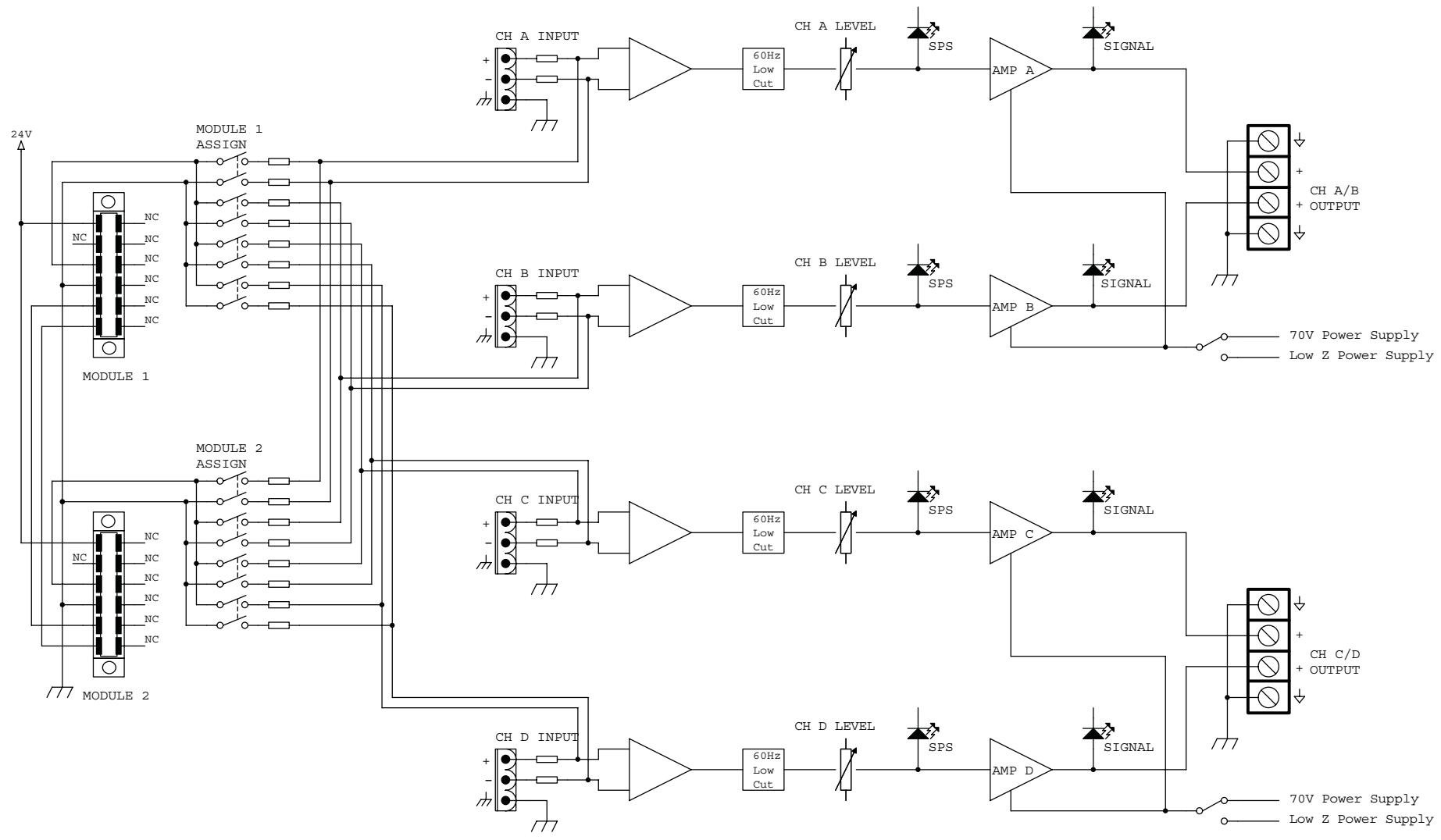
ICS™ 4200 Block Diagram
ICS™ 4200
SPECIFICATIONS
| SPECIFICATION | LOW Z MODE | 70 VOLT MODE |
| Rated Power (all channels driven)Dual-Dual Mono & Parallel Modes4 Ohms8 Ohms70 Volts | 200 Watts130 Watts | 200 Watts |
| Minimum Load Impedance | 4 Ohms | 25 Ohms |
| Bridged Mode8 Ohms16 Ohms140 Volts | 400 Watts260 Watts | 400 Watts |
| Minimum Load Impedance | 8 Ohms | 50 Ohms |
| Frequency Response+0, -1 dB @ 1 Watt+0, -3 dB @ full power | 80 Hz-35 kHz60 Hz-30 kHz | 80 Hz-30 kHz60 Hz-15 kHz |
| THD@ rated power, 1 kHz | <0.05% | <0.05% |
| IMD (SMPTE) | <0.10% | <0.10% |
| Damping Factor | >140 (8 Ohms) | >400 |
| Input CMRR | -60 dB typ | -60 dB typ |
| Voltage Gain | x20 (26 dB) typ | x50 (34 dB) typ |
| Input Sensitivity | 1.4 V (4 Ohms) typ1.6 V (8 Ohms) typ | 1.4 V typ |
| Input Impedance | 20 k Ohms balanced10 k Ohms unbalanced | 20 k Ohms balanced10 k Ohms unbalanced |
| Noise and HumBelow rated output, 22 Hz-22 kHz | -95 dB | -95 dB |
| Current Consumption (Multiply current by 0.5 for 230 V units) | ||
| Rated power | 15.4 A (4 Ohms)9.9 A (8 Ohms) | 13.2 A |
| 1/3 power | 9.9 A (4 Ohms)6.3 A (8 Ohms) | 8.6 A |
| 1/8 power | 6.6 A (4 Ohms)4.2 A (8 Ohms) | 5.8 A |
| Idle | 0.4 A | 0.7 A |
| Thermal Emission | ||
| 1/3 power | 3147 BTU/hr (4 Ohms)1990 BTU/hr (8 Ohms) | 2614 BTU/hr |
| 1/8 power | 2364 BTU/hr (4 Ohms)1500 BTU/hr (8 Ohms) | 2036 BTU/hr |
| ControlsFront: 4 channel input signal attenuators, AC switchRear: 2 x 4 DIP switches for input module assign, 2 output mode switches | ||
| Indicator LEDs4 clip, 4 signal, 1 power | ||
| ProtectionOver-temperature, DC, turn on/off transients, subsonic, incorrect load, short-circuit | ||
| ConnectorsInput: Four 3-position Euro-style detachable terminal blocks, two ports for MMATM input modulesOutput: Two 4-position barrier strips | ||
| Construction16-gauge steel-reinforced with 12-gauge rack ears | ||
| DimensionsHeight: 3.50" (8.84 cm); 2 EIA rack spacesWidth, front: 19.00" (48.26 cm)Width, rear: 17.00" (43.18 cm)Overall depth: 17.05" (43.31 cm)Mounting depth: 16.63" (42.24 cm) behind front rack ears | ||
| Weight40 lbs. (18.1 kg) | ||
| Power Requirements100, 120, 230–240 Vac, 50–60 Hz | ||
| Test Conditions120Vac, 60 Hz line input voltage maintainedAll channels operating unless otherwise noted | ||
Descripción
Características

ESPAÑOL
Entrada Módulo
DIP Switch Settings

Controles de Nivel
Modo Paralelo

Modos de Salida
All channels in 70 V mode
Dual-Dual Mono Mode Parallel Mode
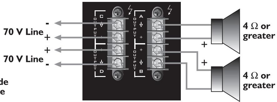
Channel A/B in Low Z Mode Channel C/D in 70 V Mode
Dual-Dual Mono Mode Parallel Mode
Example of a 70 Volt constant-voltage distribution system


ICS™ 4200
ESPECIFICACIONES
| ESPECIFICACIONES | LOW Z MODE | 70 VOLT MODE |
| Rated Power (all channels driven)Dual-Dual Mono & Parallel Modes4 Ohms8 Ohms70 Volts | 200 Watts130 Watts | 200 Watts |
| Minimum Load Impedance | 4 Ohms | 25 Ohms |
| Bridged Mode8 Ohms16 Ohms140 Volts | 400 Watts260 Watts | 400 Watts |
| Minimum Load Impedance | 8 Ohms | 50 Ohms |
| Frequency Response+0, -1 dB @ 1 Watt+0, -3 dB @ full power | 80 Hz-35 kHz60 Hz-30 kHz | 80 Hz-30 kHz60 Hz-15 kHz |
| THD@ rated power, 1 kHz | <0.05% | <0.05% |
| IMD (SMPTE) | <0.10% | <0.10% |
| Damping Factor | >140 (8 Ohms) | >400 |
| Input CMRR | -60 dB typ | -60 dB typ |
| Voltage Gain | x20 (26 dB) typ | x50 (34 dB) typ |
| Input Sensitivity | 1.4 V (4 Ohms) typ1.6 V (8 Ohms) typ | 1.4 V typ |
| Input Impedance | 20 k Ohms balanced10 k Ohms unbalanced | 20 k Ohms balanced10 k Ohms unbalanced |
| Noise and HumBelow rated output, 22 Hz-22 kHz | -95 dB | -95 dB |
| Current Consumption (Multiply current by 0.5 for 230 V units) | ||
| Rated power | 15.4 A (4 Ohms)9.9 A (8 Ohms) | 13.2 A |
| 1/3 power | 9.9 A (4 Ohms)6.3 A (8 Ohms) | 8.6 A |
| 1/8 power | 6.6 A (4 Ohms)4.2 A (8 Ohms) | 5.8 A |
| Idle | 0.4 A | 0.7 A |
| Thermal Emission | ||
| 1/3 power | 3147 BTU/hr (4 Ohms)1990 BTU/hr (8 Ohms) | 2614 BTU/hr |
| 1/8 power | 2364 BTU/hr (4 Ohms)1500 BTU/hr (8 Ohms) | 2036 BTU/hr |
| ControlsFront: 4 channel input signal attenuators, AC switchRear: 2 x 4 DIP switches for input module assign, 2 output mode switches | ||
| Indicator LEDs4 clip, 4 signal, 1 power | ||
| ProtectionOver-temperature, DC, turn on/off transients, subsonic, incorrect load, short-circuit | ||
| ConnectorsInput: Four 3-position Euro-style detachable terminal blocks, two ports for MMATM input modulesOutput: Two 4-position barrier strips | ||
| Construction16-gauge steel-reinforced with 12-gauge rack ears | ||
| DimensionsHeight: 3.50" (8.84 cm); 2 EIA rack spacesWidth, front: 19.00" (48.26 cm)Width, rear: 17.00" (43.18 cm)Overall depth: 17.05" (43.31 cm)Mounting depth: 16.63" (42.24 cm) behind front rack ears | ||
| Weight40 lbs. (18.1 kg) | ||
| Power Requirements100, 120, 230–240 Vac, 50–60 Hz | ||
| Test Conditions120Vac, 60 Hz line input voltage maintainedAll channels operating unless otherwise noted | ||
DEUTSCH
Beschreibung
Merkmale

ICS™ 4200 Endstufe
(11) Channel C/D Outputs
(14) MMA™-Plug-in-Modulanschlüsse
Paralleler Modus

70 V
All channels in 70 V mode
Channel A/B in Low Z Mode
Channel C/D in 70 V Mode
Dual-Dual Mono Mode Parallel Mode
Bridged Mode
Example of a 70 Volt constant-voltage distribution system

Description
Caractéristiques

FRANÇAIS
DIP Switch Settings


Mode Parallèle

Modes de Sorties
70 V


Example of a 70 Volt constant-voltage distribution system

NOTES:
NOTES:
Architectural Acoustics®
PEAVEY ELECTRONICS CORPORATION LIMITED WARRANTY
Effective Date: July 1, 1998
What This Warranty Covers
Your Peavey Warranty covers defects in material and workmanship in Peavey products purchased and serviced in the U.S.A. and Canada.
What This Warranty Does Not Cover
The Warranty does not cover: (1) damage caused by accident, misuse, abuse, improper installation or operation, rental, product modification or neglect; (2) damage occurring during shipment; (3) damage caused by repair or service performed by persons not authorized by Peavey; (4) products on which the serial number has been altered, defaced or removed; (5) products not purchased from an Authorized Peavey Dealer.
Who This Warranty Protects
This Warranty protects only the original retail purchaser of the product.
How Long This Warranty Lasts
The Warranty begins on the date of purchase by the original retail purchaser. The duration of the Warranty is as follows:
| Product Category | Duration |
| MediaMatrix® DPU (Excluding Frames), Cinema Processors, Power Amplifiers, Pre-Amplifiers, Mixers, Electronic Crossovers and Equalizers | 5 years |
| Loudspeakers | 5 years |
| Microphones | 2 years |
| Frames | 1 year |
| Speaker Components (incl. speakers, baskets, drivers, diaphragm replacement kits and passive crossovers) and all Accessories | 1 year |
What Peavey Will Do
We will repair or replace (at Peavey's discretion) products covered by warranty at no charge for labor or materials. If the product or component must be shipped to Peavey for warranty service, the consumer must pay initial shipping charges. If the repairs are covered by warranty, Peavey will pay the return shipping charges.
How To Get Warranty Service
(1) Take the defective item and your sales receipt or other proof of date of purchase to your Authorized Peavey Dealer or Authorized Peavey Service Center.
OR
(2) Ship the defective item, prepaid, to Peavey Electronics Corporation, International Service Center, 412 Highway 11 & 80 East, Meridian, MS 39301 or Peavey Canada Ltd., 95 Shields Court, Markham, Ontario, Canada L3R 9T5. Include a detailed description of the problem, together with a copy of your sales receipt or other proof of date of purchase as evidence of warranty coverage. Also provide a complete return address.
OR
(3) All MediaMatrix® Frames needing repair, should be shipped prepaid to Peavey Electronics Corporation, International Service Center, 412 Highway 11 & 80 East, Meridian, MS 39301
Limitation of Implied Warranties
ANY IMPLIED WARRANTIES, INCLUDING WARRANTIES OF MERCHANTABILITY AND FITNESS FOR A PARTICULAR PURPOSE, ARE LIMITED IN DURATION TO THE LENGTH OF THIS WARRANTY.
Some states do not allow limitations on how long an implied warranty lasts, so the above limitation may not apply to you.
Exclusions of Damages
PEAVEY'S LIABILITY FOR ANY DEFECTIVE PRODUCT IS LIMITED TO THE REPAIR OR REPLACEMENT OF THE PRODUCT, AT PEAVEY'S OPTION. IF WE ELECT TO REPLACE THE PRODUCT, THE REPLACEMENT MAY BE A RECONDITIONED UNIT. PEAVEY SHALL NOT BE LIABLE FOR DAMAGES BASED ON INCONVENIENCE, LOSS OF USE, LOST PROFITS, LOST SAVINGS, DAMAGE TO ANY OTHER EQUIPMENT OR OTHER ITEMS AT THE SITE OF USE, OR ANY OTHER DAMAGES WHETHER INCIDENTAL, CONSEQUENTIAL OR OTHERWISE, EVEN IF PEAVEY HAS BEEN ADVISED OF THE POSSIBILITY OF SUCH DAMAGES. Some states do not allow the exclusion or limitation of incidental or consequential damages, so the above limitation or exclusion may not apply to you.
This Warranty gives you specific legal rights, and you may also have other rights which vary from state to state.
If you have any questions about this warranty or service received or if you need assistance in locating an Authorized Service Center, please contact the Peavey International Service Center at (601) 483-5365 / Peavey Canada Ltd. at (905) 475-2578.
Features and specifications subject to change without notice.

- SAVE THESE INSTRUCTIONS!
- ENGLISH
- ICS™ 4200 Power Amplifier
- Unpacking
- Mounting
- Security Cover
- Cooling Requirements
- Operating Precautions
- Front Panel
- Power Indicator
- Signal Indicators
- Clip (SPS™) Indicators
- Input Level Controls
- AC Power Switch/Circuit Breaker
- Cooling Air Vent
- Rear Panel
- AC Mains Power Receptacle
- AC Mains Cord
- Channel A/B Output Selector (Low Z or 70 Volt)
- Channel C/D Output Selector (Low Z or 70 Volt)
- Channel A/B Outputs
- Channel C/D Outputs
- Fan Grill
- Channel Inputs
- MMA™ Plug-in Module Ports
- Module Output to Channel Selectors
- Input Connections
- Level Controls
- Attenuation in dB
- MODE CONFIGURATIONS
- Input Modes
- Dual-Dual Mono Mode
- Parallel Mode
- Bridged Mode
- Output Modes
- Low Z
- V
- ICS™ 4200
- SPECIFICATIONS
- Descripción
- Características
- ESPAÑOL
- Controles de Nivel
- Modo Paralelo
- Modos de Salida
- ESPECIFICACIONES
- DEUTSCH
- Beschreibung
- Merkmale
- ICS™ 4200 Endstufe
- MMA™-Plug-in-Modulanschlüsse
- Paralleler Modus
- Description
- Caractéristiques
- FRANÇAIS
- Mode Parallèle
- Modes de Sorties
- Architectural Acoustics®
- PEAVEY ELECTRONICS CORPORATION LIMITED WARRANTY
- What This Warranty Covers
- What This Warranty Does Not Cover
- Who This Warranty Protects
- How Long This Warranty Lasts
- What Peavey Will Do
- How To Get Warranty Service
- Limitation of Implied Warranties
- Exclusions of Damages
Brand : PEAVEY
Model : ICS 4200
Category : Sound system