APSX1012SW - Battery Tripp Lite - Free user manual and instructions
Find the device manual for free APSX1012SW Tripp Lite in PDF.

User questions about APSX1012SW Tripp Lite
0 question about this device. Answer the ones you know or ask your own.
Ask a new question about this device
Download the instructions for your Battery in PDF format for free! Find your manual APSX1012SW - Tripp Lite and take your electronic device back in hand. On this page are published all the documents necessary for the use of your device. APSX1012SW by Tripp Lite.
USER MANUAL APSX1012SW Tripp Lite
Sine Wave DC-to-AC Inverter/Chargers
Models: APSX1012SW, APSX2012SW
12VDC to 230VAC
Table of Contents
Important Safety Instructions 2
1. Overview & Features 3
1.1 Overview 3
1.2 Indicators, Controls and Settings 3
1.3 Optional Features 6
2. Battery Charger 6
2.1 Mode of Operation 6
2.2 Transfer Switching Speed 6
3. Battery Installation and Maintenance 6
3.1 Select Battery Type 6
3.2 Monthly Maintenance 8
3.3 Battery Installation 8
3.4 Battery Connection 8
4.Inverter/Charger Installation and Operation 10
4.1 Installation 10
4.2 Installation Diagrams and Charts 10
4.3 Installation and Start-Up 11
5. Technical Specifications 11
6.Troubleshooting 12
7. Service 12
Espanol 13
Francais 25
Pycckn 37

1111 W. 35th Street, Chicago, IL 60609 USA www.triplite.com/support
Copyright © 2011 Tripp Lite. All rights reserved.
Important Safety Instructions

SAVE THESE INSTRUCTIONS!
This manual contains important instructions and warnings that should be followed during the installation, operation and storage of all Tripp Lite Inverter/Chargers.
LocationWarnings
- Install your Inverter/Charger in a location or compartment that minimizes exposure to heat, dust, direct sunlight and moisture. Flooding the unit with water will cause it to short-circuit and could cause personal injury due to electric shock.
- For proper ventilation, allow a minimum 2 inches of clearance at front and back of the Inverter/Charger. To avoid overheating the Inverter, the compartment that houses the Inverter/Charger must be properly ventilated with adequate outside air flow. The heavier the load of connected equipment, the more heat will be generated by the unit.
- Do not install the Inverter/Charger near magnetic storage media, as this may result in data corruption.
- Do not install the Inverter/Charger near flammable materials, fuel or chemicals.
Battery ConnectionWarnings
- Multiple battery systems must be comprised of batteries of identical voltage, age, amp-hour capacity and type.
- Because explosive hydrogen gas can accumulate near batteries if they are not well ventilated, do not install batteries in a "dead air" compartment. The battery compartment should have some ventilation to outside air.
- Sparks may result during final battery connection. Always observe proper polarity as batteries are connected.
- Do not allow objects to contact the DC input terminals. Do not short or bridge these terminals together. Serious personal injury or property damage could result.
Ground ConnectionWarnings
- Safe operation requires connecting the Inverter/Charger's Main Ground Terminal directly to the frame of the vehicle or earth ground.
Equipment ConnectionWarnings
-
Use of this equipment in life support applications where failure of this equipment can reasonably be expected to cause the failure of the life support equipment or to significantly affect its safety or effectiveness is not recommended. Do not use this equipment in the presence of a flammable anesthetic mixture with air, oxygen or nitrous oxide.
-
You may experience uneven performance results if you connect a surge suppressor, line conditioner or UPS system to the output of the Inverter/Charger.
- User must supply proper protection for wire openings in unit panels.
OperationWarnings
- Your Inverter does not require routine maintenance.
- Potentially lethal voltages exist within the Inverter/Charger as long as the battery supply is connected. During any service work, the battery supply should therefore be disconnected.
- Do not connect or disconnect batteries while the Inverter/Charger is operating from the battery supply. Dangerous arcing may result.
1. Overview and Features
1.1 Overview
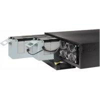
- Tripp Lite's Sine Wave Inverter-Charger is a heavy-duty unit generating a pure sine wave from a 12V battery bank. It can supply power to a wide range of connected equipment, from heaters, air conditioners, refrigerators and vacuum cleaners to computers and peripheral devices. It is designed to work in heavy load conditions, so de-rating is unnecessary.
- The smart charger is compatible with various battery types and sizes. The switch module automatically diverts the energy transfer path between the inverter and an AC input. When the AC source is lower than the transfer level, the path switches to the inverter. Otherwise, the load is powered by the AC input.
1.2 Indicators, Controls and Settings
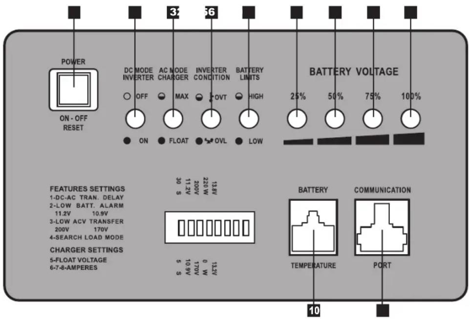
1.2.1 Controls and LED Indicators
Shown below are the control panel and indicator lights on the front panel of the Inverter/Charger.
1 Power ON/OFF Button
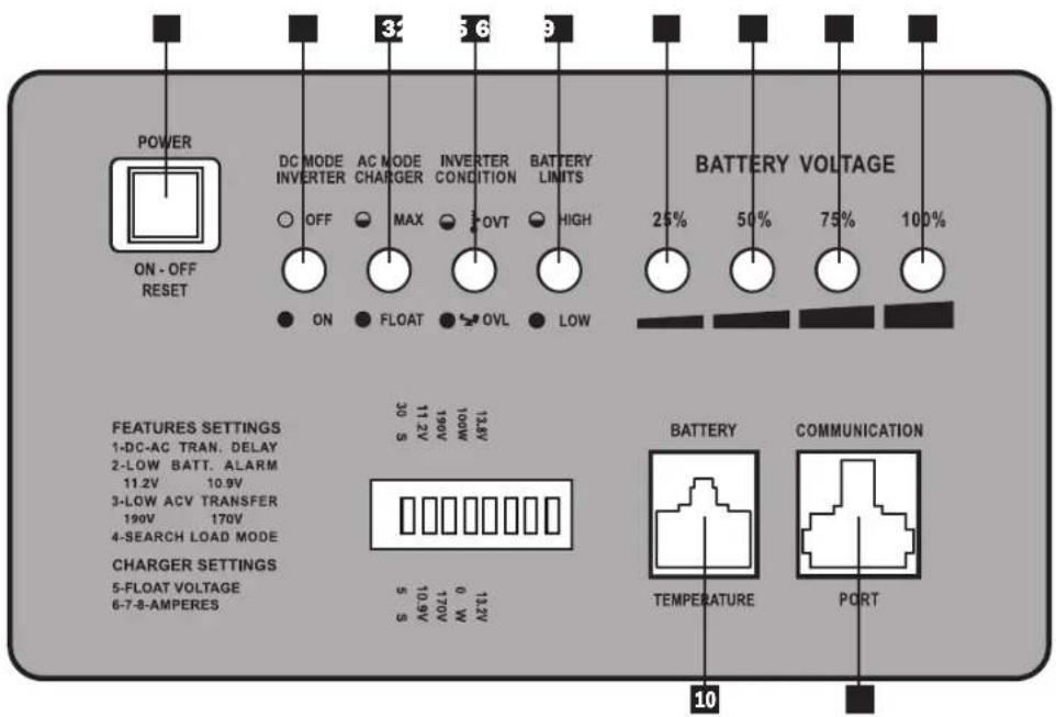
2 LED 1 - DC Mode Inverter
3 LED 2 - AC Mode Charger
4 LED 3-Inverter Condition
5 LED 4 - Battery Limits
6 LED 5 - 25% Battery Voltage
7 LED 6 - 50% Battery Voltage
8 LED 7 - 75% Battery Voltage
LED 8 - 100% Battery Voltage
10 Battery Temperature Port (RJ11)
11 Communication Port (RJ45)
1. Overview and Features
LED and Alarm Indicator
| LED 1 | LED 2 LED | 3 LED | 4 LED 5 | LED 6 LED 7 | LED 8 Alarm | ||||
| AC Normal Off | On/ Flashing | Off Off | 10.8V~11.5V 11.5 ~ | 12.5V 12.5 ~ | 13.5V >13.5V Off | ||||
| DC Mode | On | Off | Off | Off | 10.2 ~ 11.5V | 11.5 ~ 12.5V | 12.5 ~ 13.0V | >13.0V | Off |
| Battery Low (DC Mode) | On Off | Off On 1 | 0.2 ~ 1 | 1.5V 11.5 ~ 12.5V 12.5 ~ 13.0V >13.0V | 1 beep @ 5 sec for 3 min. | ||||
| Low Battery Cutoff (LBCO) | Off | Off | Off | On | Off | Off | Off | Off | 1 beep @ shutdown |
| Battery High (AC Mode) | On | Off | Off | Flashing | 10.2 ~ 11.5V | 11.5 ~ 12.5V | 12.5 ~ 13.0V | >13.0V | 1 beep @ 0.5 sec |
| Overload-129% (DC Mode) | On Off | On Off 1 | 0.2 ~ 1 | 1.5V 11.5 ~ 12.5V 12.5 ~ 13.0V >13.0V | 1 beep @ 0.5 sec | ||||
| Overload-149% (DC Mode) | On Off | On Off 1 | 0.2 ~ 1 | 1.5V 11.5 ~ 12.5V 12.5 ~ 13.0V >13.0V | On (Constant) | ||||
| Overload >150% (DC Mode) | On Off | On Off 1 | 0.2 ~ 1 | 1.5V 11.5 ~ 12.5V 12.5 ~ 13.0V >13.0V | On (Constant) | ||||
| AC Bypass Power Off | Off | Off | Off | Off | 10.8 ~ 11.5V | 11.5 ~ 12.5V | 12.5 ~ 13.5V | >13.5V | Off |
1.2.2 Power ON/OFF Button
The Power ON/OFF button is located in the left of the panel. Press to power the Inverter/Charger ON or OFF. When the button is pressed, the alarm will beep.
Note: When connected to batteries, the Inverter/Charger will start up even if not connected to AC power. Defaults to 50Hz Note: Unit is in BYPASS mode as soon as power is applied to the input.
Power On: Press the Power ON/OFF button for 3 seconds until the alarm beeps and the INVERTER MODE light illuminates.
Power Off: Press the Power ON/OFF button for 3 seconds. The alarm will beep when the shutdown process is completed.
1.2.3 DC Mode Inverter (LED 1)
This LED illuminates to indicate that the system is working in inverter mode (supplying power from battery).
1.2.4 AC Mode Charger (LED 2)
The LED flashes during the charging process and remains illuminated once the battery is full charged.
1.2.5 Inverter Condition (LED 3)
When the inverter temperature exceeds the default setting, this LED will flash and the inverter will shut down automatically. After the temperature returns to normal, depress the Power ON/OFF button to restart.
When the unit is overloaded in DC mode, LEDs 1, 3 and the audible alarm indicate inverter status as follows:
| Load Capacity (DC Mode) | LED1 | LED 3 | Alarm | INVERTER STATUS |
| 110-129% | On | On | 1 beep/0.5sec | Shutdown after 60 seconds. |
| 130-149% | On | On | On (Constant) | Shutdown after 10 seconds. |
| >150% | On | On | On (Constant) | Shutdown after 1 second. |
1.2.6 Battery Limits (LED 4)
Battery High: In AC mode, LED 4 will flash. Battery Low: LED 4 will illuminate; alarm will beep once every 5 seconds for 3 minutes. If battery voltage drops below cutoff voltage (LBCO), the inverter will shut down and only LED 4 will remain lit.
1. Overview and Features
1.2.7 Battery Voltage (LED 5-8)
LED 5-8 indicate the battery capacity as detailed in the following table:
| Battery Voltage LED 5 LED 6 | LED 7 LED 8 | |||
| 25% On — — — | ||||
| 50% On On — — | ||||
| 75% On On On — | ||||
| 100% On On On On |
1.2.8 Voltage Setting (Switch 1-3)*
| Switch ON OFF | ||
| DC-to-AC Transfer Delay (Switch 1) 30 sec (Default) 5 sec | ||
| Low Battery Alarm (Switch 2) 11.2V 10.9V (Default) | ||
| AC Transfer Voltage (Switch 3) 190V | 170V (Default) |
- Notes:
- Switches are located farthest from the battery temperature port. See diagram on page 3.
- The switches must be set before the system is turned on.
- Switch 2 sets the low battery voltage alarm level (at higher voltage setting, alarm will sound sooner).
- Switch 3 sets the low-level AC-to-DC voltage point. If the AC input voltage decreases to below the setpoint, the inverter will automatically switch to DC MODE. See the following table for details.
| Nominal Voltage | Low Voltage Transfer Point (AC-to-DC) | Return Voltage Point (DC-to-AC) | |
| 230V | On | 190 | 200 |
| Off | 170 | 180 | |
1.2.9 Search Mode Setting (Switch 4)
Search Mode activates when the unit is operating in inverter mode (battery power) to prevent unnecessary battery discharge when electrical power is not required. If the inverter is supporting loads that must constantly be powered, turn off switch 4 to disable Search Mode.
| Switch 4 | Search Mode | Function |
| ON | Enable | Inverter turns on only if load is >100W |
| OFF (Default) | Disable | Inverter always on if AC power is absent |
1.2.10 Floating Voltage/Battery Type (Switch 5)
| Switch 5 | Floating Voltage | Acceptance Voltage | Battery Type |
| ON (Default) | 13.8V | 14.5V | Absorbed Glass Mat (AGM) |
| OFF | 13.2V | 13.8V | Wet-Cell |
Note: The unit will charge the battery to acceptance voltage, continue for 1 to 12 hours, then drop to floating voltage.
1. Overview and Features
1.2.11 Battery Charging Rate Setting (Switch 6, 7 & 8)
These switches control the maximum charging rate in amps. The charge rate has 8 stages. It can be adjusted by setting these switches as shown in the following table:
| Switch 6 | ON ON | ON ON OFF | OFF OFF OFF | |||||
| Switch 7 | ON ON | OFF OFF ON | ON OFF OFF | |||||
| Switch 8 | ON | OFF | ON | OFF | ON | OFF | ON | OFF |
| APSX1012SW | 40A 32A | 24A 20A (Default) | 16A | 12A 8A | 4A | |||
| APSX2012SW | 60A 48A | 36A 30A (Default) | 24A | 18A | 12A 6A |
Note: The charging rate depends on the battery bank size. Consult the battery manufacturer's specs for the maximum allowed charge rate (usually 0.3 times the AH rating).

Caution! An excessively high charging rate can overheat the battery. If a small-capacity battery is used, set the battery charge rate to the minimum setting.
1.3 Features
1.3.1 Battery Temperature Port
This port allows connection of a Battery Temperature-Sensing Cable (sold separately). The sensing function prolongs battery life by adjusting the charge float voltage level based on battery temperature. Connect the sensor cable to the RJ11 port labeled "Battery Temperature." With user-supplied electrical or duct tape, secure the sensor to the side of the battery below the electrolyte level. Make sure that nothing, not even tape, comes between the sensor and the side of the battery. To guard against false readings due to ambient temperature, place the sensor between batteries if possible and away from sources of extreme heat or cold. If the sensor cable is not used, the Inverter/Charger will charge according to its default 25^ values.
1.3.2 Communication Port (for APSRMSW Remote Control)
This port allows connection of the APSRMSW Remote Control (sold separately). The remote control allows the Inverter/ Charger to be mounted out of sight in a compartment or cabinet and operated conveniently from a remote location. See the instructions packed with the remote control module for more information.
2. Battery Charger
2.1 Mode of Operation
The internal battery charger and automatic transfer relay allow the unit to operate as either a battery charger or an inverter. An external AC power source (e.g. shore power or generator) must be connected to the inverter's AC input in order to allow it to operate as a battery charger. When the unit is operating as a charger, AC loads are powered by the external AC power source.
2.2 Transfer Switching Speed
Transfer time is less than 16 milliseconds.
3. Battery
3.1 Select Battery Type
Select 12V "Deep Cycle" batteries to receive optimum performance from your Inverter/Charger. Do not use ordinary car or starting batteries or batteries rated in Cold Cranking Amps (CCA). If the batteries you connect to the Inverter/Charger are not true Deep Cycle batteries, their operational lifetimes may be significantly shortened. If you are using the same battery bank to power the Inverter/Charger as well as DC loads, your battery bank will need to be appropriately sized (larger loads will require a battery bank with a larger amp-hour capacity) or the operational lifetimes of the batteries may be significantly reduced.
Batteries of either Wet-Cell (vented) or Gel-Cell /Absorbed Glass Mat (sealed) construction are ideal. Set Switch 5 to OFF for Wet-Cell batteries and ON for Absorbed Glass Mat (AGM) batteries. Two 6-volt "golf cart", Marine Deep-Cycle or 8D DeepCycle batteries in series are also acceptable. In many cases, the vehicle battery may be the only one installed. Auxiliary batteries must be identical to the vehicle batteries if they are connected to each other.
3. Battery
3.1.1 Match Battery Amp-Hour Capacity to Your Application
Select a battery or system of batteries that will provide your Inverter/Charger with proper DC voltage and an adequate amp-hour capacity to power your application. Even though Tripp Lite Inverter/Chargers are highly efficient at DC-to-AC inversion, their rated output capacities are limited by the total amp-hour capacity of connected batteries and the support of your vehicle's alternator if the engine is kept running.
Example
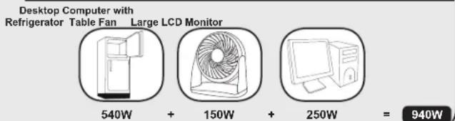
- STEP 1) Determine Total Wattage Required
Add the wattage ratings of all equipment you will connect to your Inverter/Charger. Wattage ratings are usually listed in equipment manuals or on nameplates. If your equipment is rated in amps, multiply that number times AC utility voltage to estimate watts. (Example: a drill requires 2.8 amps. 2.8 amps × 230 volts = 640 watts.)
NOTE: Your Inverter/Charger will operate at higher efficiencies at about 75% - 80% of nameplate rating.
Tools
13mm(1/2")Drill
Orbital Sander
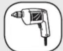
640W
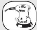
220W

860W
Appliances and Electronics
Desktop Computer with Refrigerator Table Fan Large LCD Monitor
540W
150W
250W

940W
STEP 2) Determine DC Battery Amps Required
Divide the total wattage required (from step 1, above)
by the nominal battery voltage to determine the DC amps required.
940 watts ÷ 12V =78 DC Amps
- STEP 3) Estimate Battery Amp-Hours Required
Multiply the DC amps required (from step 2, above) by the number of hours you estimate you will operate your equipment exclusively from battery power before you have to recharge your batteries with utility- or generator-supplied AC power. Compensate for inefficiency by multiplying this number by 1.2. This will give you a rough estimate of how many amp-hours of battery power (from one or several batteries) you should connect to your Inverter/Charger.
NOTE: Battery amp-hour ratings are usually given for a 20-hour discharge rate. Actual amp-hour capacities are less when batteries are discharged at faster rates. For example, batteries discharged in 55 minutes provide only 50% of their listed amp-hour ratings, while batteries discharged in 9 minutes provide as little as 30% of their amp-hour ratings.
78 DC Amps × 5 Hrs. Runtime
× 1.2 Inefficiency Rating = 468 Amp-Hours
STEP 4) Estimate Battery Recharge Required, Given Your Application
You must allow your batteries to recharge long enough to replace the charge lost during inverter operation or else you will eventually run down your batteries. To estimate the minimum amount of time you need to recharge your batteries given your application, divide your required battery amp-hours (from step 3, above) by your Inverter/Charger's rated charging amps (depending on the Switch 6, 7 and 8 ON/OFF settings).
NOTE! For Tripp Lite Inverter/Chargers providing 1000 watts or less of continuous AC power, a full-size battery will normally allow sufficient power for many applications before recharging is necessary. For mobile applications, if a single battery is continuously fed by an alternator at high idle or faster, then recharging from utility or generator power may not be necessary. For Tripp Lite Inverter/Chargers over 1000 watts used in mobile applications, Tripp Lite recommends you use at least two batteries, if possible fed by a heavy-duty alternator any time the vehicle is running. Tripp Lite Inverter/Chargers will provide adequate power for ordinary usage within limited times without the assistance of utility or generator power. However, when operating extremely heavy electrical loads at their peak in the absence of utility power, you may wish to "assist your batteries" by running an auxiliary generator or vehicle engine, and doing so at faster than normal idling.
468 Amp-Hours ÷ 40 Amps
Inverter/Charger Rating
11.7 Hours Recharge
3. Battery
3.2 Monthly Maintenance
- Check the electrolyte level of each Wet-Cell battery cell monthly after the batteries have been charged. The level should be about one-half inch above the top of the plates, but not completely full. Note: This check is not necessary for maintenance-free batteries.
- Check the battery connections for tightness and corrosion. If any corrosion is noted, disconnect the cables and clean them with a mild solution of baking soda and water. DO NOT ALLOW THE SOLUTION TO ENTER THE BATTERY. When finished, rinse the top of the battery with clean water.
- To reduce corrosion on the battery terminals, coat them with a thin layer of petroleum jelly or anti-corrosion grease. Do not apply any material between the terminal and the cable lugs; the connection should be metal to metal. Apply the protective material after the bolts have been tightened.
3.3 Battery Installation

Caution! Batteries can produce extremely high currents. Review both the important safety instructions at the beginning of this manual and the battery supplier's precautions before installing the inverter and batteries.
3.3.1 Battery Location
Batteries should be installed in an accessible location with good access to the battery caps and terminals. At least two feet of overhead clearance is recommended. Batteries must be located as close as possible to the inverter. Do not install the inverter in the same compartment with non-sealed batteries (sealed batteries are acceptable). The gasses produced by non-sealed batteries during charging are highly corrosive and will shorten the life of the inverter.
3.3.2 Battery Enclosure
Batteries should be installed in a locked enclosure or room. The enclosure should be well ventilated to prevent accumulation of hydrogen gasses that are released during the battery charging process. The enclosure should be made of acid-resistant material or coated with an acid-resistant finish to prevent corrosion from spilled electrolyte and released fumes. If the batteries are located outdoors, the enclosure should be rainproof and have mesh screens to prevent insects and rodents from entering. Before installing the batteries in the enclosure, cover the bottom with a layer of baking soda to neutralize any acid spills.
3.4 Battery Connection
3.4.1 Connect your Inverter/Charger to your batteries using the following procedures:
- Connect DC Wiring: Though your Inverter/Charger is a high-efficiency converter of electricity, its rated output capacity is limited by the length and gauge of the cabling running from the battery to the unit. Use the shortest length and largest diameter cabling to provide maximum performance (see table below). Shorter and heavier-gauge cabling reduces DC voltage drop and permits maximum transfer of current. Your Inverter/Charger is capable of delivering peak wattage at up to 200% of its rated continuous wattage output for brief periods of time. Heavier-gauge cabling should be used when continuously operating heavy-draw equipment under these conditions. Tighten your Inverter/Charger and battery terminals to approximately 3.5 Newton-meters of torque to establish an efficient connection and to prevent excessive heating at the connection. Insufficient tightening of the terminals could void your warranty.
Maximum Recommended DC Cable Length
Maximum Distance From Battery to
Inverter/Charger
| Output | Wire Gauge (AWG) | ||
| 20 00 | (2/0) | ||
| 1000W | 20 ft 31 ft 39 ft | ||
| 2000W | Do not use Do not use | 20 ft | |
3. Battery
- Connect Fuse: NEC (National Electrical Code) article 551 requires that you connect all of your Inverter/Charger's positive DC Terminals directly to a UL-listed fuse(s) and fuse block(s) within 18 inches of the battery. The fuse's rating must equal or exceed the minimum DC fuse rating displayed on the Inverter/Charger's nameplate. See diagrams below for proper fuse placement.

WARNING! - Failure to properly ground your Inverter/Charger to a vehicle's chassis or earth ground may result in a lethal electrical shock hazard.
- Never attempt to operate your Inverter/Charger by connecting it directly to output from an alternator rather than a battery or battery bank.
- Observe proper polarity with all DC connections.
3.4.2 Non-Vehicular or Vehicular
Your Inverter/Charger's Nominal DC Input Voltage must match the voltage of your battery or batteries—12 volts in most vehicular applications.
It is possible to connect your Inverter/Charger to the main battery within your vehicle's electrical system. In most vehicles, the Inverter/ Charger will be connected to one or more dedicated auxiliary (house) batteries, isolated from the drive system to prevent possible draining of the main battery.
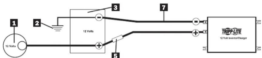
12 Volt Main Battery Connection
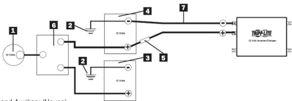
12 Volt Main and Auxiliary (House) Battery Connection (Isolated Parallel)
1 12-Volt Alternator
2 Vehicle Battery Ground
3 12-Volt Main Battery
4 12-Volt Auxiliary (House) Battery
5 UL-Listed Fuse & Fuse Block (mounted within 18 inches of the battery)
6 Battery Isolator
7 Large Diameter Cabling
4. Installation and Operation
4.1 Installation
4.1.1 Environment
The Inverter/Charger must be installed in a protected location that is isolated from sources of high temperature and moisture.
To assure peak performance, battery cables should be kept as short as possible. However, do not install the Inverter/Charger in the same compartment as non-sealed batteries. Accumulated hydrogen and oxygen generated by the batteries could be ignited by an arc (resulting from connection of the battery cables) or by switching a relay.
The Inverter/Charger requires unrestricted air flow to operate at high power for sustained periods. Do not mount the inverter in an enclosed space. This will restrict air flow and cause the inverter's protection circuitry to activate, reducing maximum available power.
4.1.2 System Grounding
Proper grounding is essential to assure safe operation of the Inverter/Charger. Grounding requirements vary by country and application. For specific requirements pertaining to your location and application, consult local codes and the NEC.
4.2 Installation Diagrams and Charts
4.2.1 Terminal Block (AC Side)
4. Installation and Operation
4.3 Installation and Start-Up
4.3.1
Connect the unit to the batteries per Section 3. Ensure that the nominal DC battery voltage is 12V
4.3.2
Connect the unit to the AC load. Then connect to the AC source. Confirm that all wiring is correct and terminal is tight.
4.3.3
Press the ON/OFF button. The system will start working after a few seconds. If the AC source power fails, the unit will work in Inverter mode. Otherwise, the system will switch to AC Mode and will power the load while charging the battery.
5. Technical Specifications
| Model Specification | APS1012SW | APS2012SW |
| Continuous Power 1000 Watts 2000 Watts | ||
| Peak Inverter Efficiency >82% | ||
| Output Waveform Sine Wave | ||
| DC Current at Rated Power 120 Amps 240 | Amps | |
| Recommended Battery Fuse 200 Amps 400 | Amps | |
| Nominal Input Voltage 12 VDC | ||
| DC Input Voltage Range 10.0 ~ 16 VDC | ||
| Low Battery Protection (Heavy/Light Load) 10 | 0.9/11.2 VDC | |
| DC Mode Output Voltage Regulation +/- 10% | ||
| Power Factor Allowed 0.8 to 1 | ||
| Frequency Regulation | 50/60 Hz, +/- 0.5 Hz (Autoselect) | |
| Standard Output Voltage | 230 VAC | |
| Load Sensing (Power Saving) | 100W | |
| Transfer Time | 16 ms max | |
| Forced Air Cooling | Variable Speed | |
| Automatic Transfer Relay | 15A | 30A |
| Adjustable Charge current | 4 ~ 40 A | 6 ~ 60 A |
| Resistive Load | 100% | |
| Inductive Load | YES | |
| Motor Load | YES | |
| Rectifier Load | YES | |
| Wall-Mounting | YES | |
6. Troubleshooting
- Your Inverter/Charger requires no maintenance and contains no user-serviceable or user-replaceable parts, but should be kept dry at all times. Periodically check, clean and tighten all cable connections as necessary, both at the unit and at the battery.
- A small-size battery being charged at a higher charging rate could cause an overvoltage shutdown. To prevent this, reduce the charge rate or discharge the battery before recharging.
- If the Inverter does not start up properly, disconnect the system from the battery for 30 seconds, then repeat the startup procedure. If the system still does not start up properly, visit www.triplite.com/support.
7. Service
Your Tripp Lite product is covered by the warranty described in this manual. A variety of Extended Warranty and On-Site Service Programs are also available from Tripp Lite. For more information on service, visit www.triplite.com/support. Before returning your product for service, follow these steps:
- Review the installation and operation procedures in this manual to insure that the service problem does not originate from a misreading of the instructions.
- If the problem continues, do not contact or return the product to the dealer. Instead, visit www.triplite.com/support.
- If the problem requires service, visit www.triplite.com/support and click the Product Returns link. From here you can request a Returned Material Authorization (RMA) number, which is required for service. This simple on-line form will ask for your unit's model and serial numbers, along with other general purchaser information. The RMA number, along with shipping instructions will be emailed to you. Any damage (direct, indirect, special or consequential) to the product incurred during shipment to Tripp Lite or an authorized Tripp Lite service center is not covered under warranty. Products shipped to Tripp Lite or an authorized Tripp Lite service center must have transportation charges prepaid. Mark the RMA number on the outside of the package. If the product is within its warranty period, enclose a copy of your sales receipt. Return the product for service using an insured carrier to the address given to you when you requested the RMA.

WEEE Compliance Information for Tripp Lite Customers and Recyclers (European Union)
Under the Waste Electrical and Electronic Equipment (WEEE) Directive and implementing regulations, when customers buy new electrical and electronic equipment from Tripp Lite they are entitled to:
- Send old equipment for recycling on a one-for-one, like-for-like basis (this varies depending on the country)
- Send the new equipment back for recycling when this ultimately becomes waste
Regulatory Compliance Identification Numbers
For the purpose of regulatory compliance certifications and identification, your Tripp Lite product has been assigned a unique series number. The series number can be found on the product nameplate label, along with all required approval markings and information. When requesting compliance information for this product, always refer to the series number. The series number should not be confused with the marking name or model number of the product.
Tripp Lite follows a policy of continuous improvement. Product specifications are subject to change without notice.

1111 W. 35th Street, Chicago, IL 60609 USA
www.triplite.com/support
201110117·939054-EV
1111 W. 35th Street, Chicago, IL 60609 USA
www.triplite.com/support
Copyright © Tripp Lite, 2011. Todos los derechos reservados.
1111 W. 35th Street, Chicago, IL 60609 USA
www.triplite.com/support
201110117·933054-E3
Guide d'utilisation
CONSERVEZ CES INSTRUCTIONS!
| Load Capacity (DC Mode) | LED1 | LED 3 | Alarm | INVERTER STATUS |
| 110% | On | On | 1 beep/0.5sec | Shutdown after 60 seconds. |
| 130% | On | On | On (Constant) | Shutdown after 30 seconds. |
| >150% | — | On | Shutdown | Shutdown after 2 seconds. |
1.2.6 Battery Limits (Limits de la batterie) (DEL 4)
940 watts ÷ 12V = 78 CC Amps

m = 311 ;
1111 W. 35th Street, Chicago, IL 60609 USA
www.triplite.com/support
2011.0117·939054-FR
PykoBODCTBO NOJIb3OBaTeIa
www.triplite.com/support
AByTopckne npaba © 2011. Tripp Lite. Bce npaba zauuueHbI.
Baxkhble nHctpyKznn no TexhNke 6e30nacHOCTN

COXPAHNTE 3TN INHCTPYKUNI!
B HactoIeM pyKOoDCTBe coepKaTcBaXHbIe NHCtpyKUIN I npEOctEpEKeHnA, KOtOble Heo6xOaIMo Co6JIIOdaTb B XOJe yCTaHOBKn, 3KcIIyatauIN xpaHEHn BCex Ipeo6pa3OBaTeIe/3apraNbIX yCTpOiCTB Tripp Lite.
Yka3aHnno BbI6opy MeCToNoLoXeHHa
- UctaHOBtpe Pneobpa3oBATEb/3apnHoe yCTPOcTBO B MecTe C MNHMaNBbIM DOCTyNOM TENla, PbJIN, npMORO coHHeHOro CBeta n BlaI. NonaDahne BObl Ha np6Op Bb3OBet KOpOTKoe 3amblaKaHne, KOtOpoe MoKET npNBecTn K HechactHOM cyuAIO B pe3yNbTaTe ydapa 3JIeKTpUHeCKIM TOKOM.
- I30JIaHNOHoe paCCToHHe OE TpePeHne H 3aHHe Yacte PpeO6pa3OBaTeJIa/3apJdHO yCTPOCTBA DoJHKo COCTABJIbTb 2IIOHMa DnI OecNcEHHaHaJIe XeKaIe BENTINaI. Bo I36eKaHHe NpePepBa PpeO6pa3OBaTeJIa NOMeUeHHe, B KOTOpOM HaxOHTcA PpeO6pa3OBaTeJIb/3apJdHO yCTPOCTBO, DOJKNHO pOBoETpNBaTcB aTMOCΦePHbIM BO3dyXOM. Yem BoNbIe Harpy3ka NoCoEInHEnHOrO o6OpYDoBaHJIa, TEM BoNbIe TeNla reHepnPye Tnp6Op.
- He yctahabnbaite Ppeo6pa30BaTeIb/3apraHoe yctpoCTBO B HENOCpeiCTBEHHO 6n30CTN OT MaHHTHO NaKoINTEJI, NocOJIbky 3TO MOKeT pINBecTNI K NCKaKeHIO daHHbIX.
- He yctaHaBnBaIte yCTpoiCtBO pIOM C JERKOBOCIIaMeHraOuMnCRA MaTePnaJAMN, TOJIINBOM ININ XIMnueCKMN BSeIeCTBaMn.
He moHTnpyIe annapat taKIM o6pa3OM, yTO6bI erO nepeHnA nn 3aHnA naHEnb 6bln o6paueHb BnH3 (IOJ IIO6bIM yrIOM). HecobnoJeHne 3Toro Tpe6oBaHnE cepBe3HO hapuWnt BHyTpEHHe oxnaXdHne annapaTa, YTO B KOHcE KOHcB npBedeT K erO noBpeXdHnO, Ha KOToPoE He paCpNoCtpaHReTcraPANTN.
Yka3aHnno no noDcoeHHeHnO aKKymyIaTopa
MHOOrOeMeHTBHeAkkMyrTOpHbI CnCTeMbI DOJXHbI COCToRbN3 AKKMyrTOpOB C OINHaKOBbIM HAnpJKeHNEM, cpoKOM Cnyk6bl, EMKoCTbIO B aMneP-Yacax N TINOM.
B BnDy TORO,TO pRdOM C aKKMyJrTopaMIM MOKe T cKaJIINBaTcBc B3pbIBOONacHbI BOOpO npN OTCyTCTBm HAdnHexaJero yPOBHe BENTINaUM, He yCTaHaBnBaIte aKKMyJrTopbI B NOMEueHIn C 3actOnHbIM Bo3dyXOM). JyUe BCero, YTo6bl NOMEueHIn XopoIo npoBeTpnaIocb atMOOCpepHbIM Bo3dyXOM.
B XoJe OkOnHateNbHOy YcTaHOBKn AKKMyIaTOpOB MoKeT NOBnTbCnCKpeHne. Pn NocoeHNHeHn AKKMyIaTOpOB Bcerda npOBepeRte noJrpHOCTb.
- 136eraTe KOHTaTnpeMeTOB C KNeMMaMn BBOda NocToHnO ToKa. He CoeINHrTe 3Tu KneMMbI DpyrC dpyrom, TAK KaK 3TO MOKeT npNBecTI K HecuactHOMy CnyaIO IJN NOBpeXdEHHIO MMyueCTBa.
Yka3aHnno 3a3emJenHIO
-Дяобсесеньбз�анрабotIпeobpa3OBATEЯ/3apdHOrOyctpoCTBaeroOCHOHON3aEMNIOUINBBIBODdoJxENbItbHaPpMycOeINHeC«MacCO»ABTomoBnIJNIN3aEmneH.
Yka3aHnno no noDcoeHNHeHHo 06OpydoBaHn
-
He pekomeHdyetcncnOb30BaT daHoe obopyoBaHne dnaXn3Heo6ecneHnKordaOTka3 daHHoro obopyoBaHn MoKeT npBecTn K OTka3y annapaTybl Xn3Heo6ecneHn IIN 3HaHTeNbHO NOBnraTb Ha ee 6e3OnacHocTb nIn 3ΦΦeKTHNBocTb. He nCNoJIb3yIte daHnoe obopyoBaHne npn HauNn INERKOBCnPAMEHIOuei cAheCTeTuCeckOcmecn BO3Dyxa, KICNOPoDa nn OKCnDa a3ota.
-
Pn noDcoeHHeHH orpaHHTeJI nepeHaPRAKeHH, yCTpoiCTBa 3aIITbI OT 3JIeKTPueCKHX NOMEX INI CNCTEmbl I6II K BbIXOy IIpeo6pa3OBeTAE/3apJdHOrO yCTpoiCTBa MOrY T Bo3HNKHyTB NOMEXN B erO pa6Ote.
-Пользовател Должен Осесеньи Т haндахашиу 3aшиу kaбелььх BBOДОВ B naHEJIX yCTpoiCTBa.
Yka3aHnno əKcnIyatauHn
- Het Heo6xoJIMOCtI npOoBntb NOBceHHeBHOeTexHnueCKoe 6cnyKuBaHne Ipeo6pa3ObaTeTna.
- PnHaHmNnAkkMyIaTOPHO NITAHNcCyUeCTByET NOTeHcuaJIbHra ONaCHOCTb BO3HKnHOBeHnCMEpeTbHO HAnpJKeHnIpeo6pa3ObaTeJIa/3apJdHOrO yCTpoIcTBa.BCB3N C 3TNM dIpyPiPoBeHeHnJIIO6oRTOxHnueCKoO 6cbNyKbHnHHeo6XoDnMo OTCoEduHHb AkkMyIaTOPHOe NITaHHe.
He noDcoeHnHae He oTcoeHnHae aKkyMnyaToBb,ecnI Ppeo6pa3oBaTeNb/3apAnHoe yCTpoiCTBO pa60Taet Ha aKKyMnyaToPbHom nHTaHm. 3TO MoKeT pNBeCTN K o6pa3oBaHnO onaChon 3JeKTpuecko dyu.
1. 0630р n Функци
1.1 063op
Ipeo6pa30BaTeJIb CInHycondaIbHoro TOka - 3apJdHoe yctpoCTBO Tripp Lite ABJrEcTc ycInHeHbIM y3IOM, reHepnpyUOIm MucCTyIO CInHycondaIbHy IOBHy AKKMyIaTOpHOro 6Noka, paccuHTaHHoro Ha 12B. OH MOKe TcLyKntb NCTOCHIKOM PITAHN DnI CENoRo CNEKTpa NOcOeINHReMOrO ObOpyDObAHN; OT ObOrpeBaTeJIe, KOHNIOHePOB, XONODINbHKNOB IN PbIEcOCOB, DO KOMNbIoTEpOB IN nepiΦepnHbIX yCTPOcTB. OH MOKe paBoTaTB B peXmte TJeKJIbIX Harpy3OK, PO3tOMy Heo6xoDmOcTB B DeΦopCnpOBAHN OTCytCTByET.
3apndoe yctpoCBO COBmecTMO C pa3nHbIMN TINAMN INa3MepamN AKKymyIaTOPOB. IpeeknOaTeNB aBTOMaTHueCKN MeHReT NytB nepeDaay 3HeprMN MExdy npeo6pa3OBaTeENM IN BBOdom npeMeHHoro TOka. Korda HCTOuHnik nepemehHoro TOKa HIXe yPOBHa nepeDauN, NytB npeoknOuaetc Ha npeo6pa3OBaTeJIb. DpymN cIOBaMn, MOUHOCTB HArpy3Ke CO3dAeTCB BBOOM npeMeHHoro TOka.
Bpemnpeo6pa30BaHnncocTaeT 10 MmJIInceKHyHd.
1.2 INdikKaTopbI, perylnpyoJne yctpoNCTBa n HacTPOKn
1.2.1 Perynnpuyoune yctpoiCTBa n CBeToaNoAHbIe HAnKaTOpbl
Tak BBirnaynt KOHTpObnHbIy Iun n CBeTOBbIe INHdNkATOpbl nepeDne naHeI Ppeo6pa3OBaTeIa/3apAnHO rYcTpoiCTBa.
1 Khonka Bkn/Bbikn (ON/OFF)
2 INH1- Ppeo6pa30BaTeenbBpek.DC
3 INД 2-3ap. yctp-BO B pexmme AC
4 INH3-INBepToPbI peKIM
5 INH4-JIIMMTbIaKKMyJyToppa
6 INHД 5-HanpЯжениakkymnyaTopa 25%
7 INH6-HanpKaHeNekkymyIaTopa 50%
8 INH7-HanpJxKeHne aKKymyIaTopa 75%
9 INH8-HanpexeHne akkymyjTopa 100%
10 TemnepaTyPhbI npT aKKMyJyTopa(RJ11)
11 NopT CBa3n (RJ45)
1. 0630р n Функци
CBeToIONoHbIe 3ByKOBbIe HnDnKaTOpbl
1.2.2 Khonka Bkn/BbKn (ON/OFF)
KhONka BkN/ByIK (ON/OFF) pacnoJIOXeHa B neBOH qaTn naHeH. HaxMnte Ha ON nIIN OFF dIy BKIOHcHnA nn BbIKIOHEn Ipeo6pa3ObaTeJI/3apdHoro yCTpoiCTBa. Pn HaxKaTHN KhONKn pa3dAcTc 3ByKOBo CNrHaI.
PnmuueHHe: PnnoCoeHHeH K aKKyMnyTOpam Ppeo6pa30BaTeIb/3apAHOe yCTpoIcTBO BKJIouHTcR daKe npOCTBm coeHHeH K cETn AC. No yMOJuaHIO 50 T.
PpmeaHHe: cpa3y nocLe noaun nntanHa bXoJ yCtpoNCTBO nepexoJNT B pexm pa60TbI no o6xoJHOu ceHn.
Bknouhen nntaHn: HaxmTe KhoNky ON/OFF n ydepKnaIte ee 3ceyHbI do Tex np, noka He noBtca 3BykoBoi cnHaI n He 3arOpNTc nHdkatop INVERTER MODE (HHeptpHbI peXm).
Bbikluoyehne nitaHn: No 3aBepueHH npouecca oTKluoyehn Bbl ycbiunte 3BykoBoCnHaI.
1.2.3 Ppeo6pa3oBaTeJb B pexmme DC (MHd 1)
3TOT INHINKATOP 3aropaeTcR, KOrda CnCTema pa6oTaET B INHBepTOPHOM pexmme (NITAHne NOaTeC T OAKyMnyTota).
1.2.4 3apnHoe yctpoNCTBO BpeXmE AC (HH2)
INHdkatop Mrraet BO Bpemr npoucecca 3apdkn N OCTaETCBAKIOHcHHbIM DO NNHO rO3apda aKKymyIaTopa.
1.2.5 INHBeptOpHbI peKm (NH3)
B cnyuae, korga temnepatypa nHBeptopa npebblaaet yctahOBJIeHHbI 6e3oanchbI ypOBeHb, daHHbI CND hauHaet MrraTb, a nHBeptop abTomatueckn OTKnHouaetcra.
Pocne BocctaHOBJIeHn HOpMaIbHOro yOpBnTe TempeApTybl POn3BeDInTe nepe3arpy3ky HaKaTHem KHOJKN «Power ON/OFF».B cIyueae neperpy3kn daHHoro 6JIOka B pexIme pa6Otbl OT NcTOUHnka NOCTOARHOro TOKA COCTOHRHe INHBepTopa oTo6paKaetaTcra nOMoUbHO CIV 1, 3 n 3ByKOBOrO cnHana CNe dyUoUM o6pa3OM:
| Harpuzhuchangocoboctb (pekmDC) | iHД 1 | iHД 3 | 3BykoBoJ cnHnAл | CTATYC IPEO6PA3OBATEJIa |
| 110% | Bkn | Bkn | 1 rydok/0.5 cek | OTKliouchenie no ictechenii 60 sekynd. |
| 130% | Bkn | Bkn | Bkn (noctoHHbI) | OTKliouchenie no ictechenii 30 sekynd. |
| >150% | — | Bkn | OTKliouchenie | OTKliouchenie no ictechenii 2 sekynd. |
1.2.6 JIIMHTbI aKKymyToppa (MH4)
Bbockn ypoBeH 3aprae BpeKme pa6oTb OT cetn nepeMeHHoro ToKa OTo6paXaetcM rHaHem Cn4. Hn3Kn ypoBeH 3aprae 6atapen: 3aropaeTcCn4, conpOBOxdaemb 3ByKOBbIM CnHaIOM kKaJbIe 5cekyH B TeueHne 3 MNHT. Ppi noHNKeHnn HaprrkHeHna 6batape HNKe 3Naue HNKe OTeck (peKm OTKNoHcHn 6batape npi NOHNKeHn HaprrKeHn) pONCXODNT OKNIOUHeH nHBepTopa, nocne Yero pa6oTaIOUM oCTaETc TOnbKO Cn4.
1. 0630р n Функци
1.2.7 HanpajkeHne akkymyIaTopa (HH5-8)
INdkaTOpbI 5-8 noka3bBAoHnpanjKeHne aKKyMylTopa cornacho cneDyUoE Ta6nue:
| Наръжение akкumулаятора | MHД 5 ИнД 6 ИнД 7 ИнД 8 | ||
| 25% Bкн — — — | |||
| 50% Bкн Bкн — — | |||
| 75% Bкн Bкн Bкн — | |||
| 100% Bкн Bкн Bкн Bкн |
1.2.8 YcTaHOBKa HAnpJxKeHH (IpepeKIOuOaTeHN 1-3)
Appliances and Electronics
- 3TAN2) OnpeDenite Heo6xOmyCnny NocToHHoro Toka aKMyrITopa
Pa3deneObuHNO Heo6xOIMyMOUHocb (paccHTaHHyHa 3TaIe 1) Ha HOMHaJIbHOe HApJXeHHe aKKMyJrTOpa dIra ONpeJeHnna Heo6xOIMoCINbl NOCToAHORo Toka.

- 3TAN3) PaccunTaIe Heo6xOaMyu eMKocb aKKyMnyTopa B amnep-uaacax
YMHOKTe HeoXOIMyIO Cnny NoCToHHORO TOKa (paccHTaHHUHO Ha 3Tane 2)Ha KOnIueCTBO YacOB, B TeeHHe NKTOpbIX BaWe o6OpyDobAHne 6yET paOToTb ToIbKO OT aKKMyJrTOphoro NITAHN Do NO3apAKn aKKMyJrTOPOB OT cEtN IepMeHHORO TOKA 3NeKTPocTe NIN rHEpaTOPa. BocONHInTe HeoCTaTOOHCTb, yMHOxINB 3TO YcCNO HA 1.2. TaKIM O6pa3OM, Bbl np6bn3ntelbHo paccHTaTe, KaKyIO EMKOCbT aKKMyJrTOpaNTAHN BAMnep-uaax (OT OndHO rIN HeCKOJIbKnx AKKMyJrTOPOB) HxKHO nOcEOHNbK BaWemy Ppeo6pa3OBaTeIO/3apAnHomy yCTpoiCTBy.
PIMMEAHHE: EMMKCTN AKKMYIATOPA B AMNEP-Yacax, KAK npabINIO, yka3bIaHOTc DnT 20-yaocBOro paoRda. DaKTHueCKHe EMMKCTN B AMNEP-Yacax MEHbUe, KOgDA aKKMyIaTOpbl paarKaIaTOC 5bIcTpee. HanpMep, aKKMyIaTOpbl, paarPaKaMaIbeYepe3 55 MHyT, o6Naiaot NIIuS 50% yka3aHIOH EMKCTB B AMNEP-Yacax, B TO BpEmaK AkkMyIaTOpbl, paarPaKaMaIbe Yepe3 9 MHyT, o6Naiaot NIIuS 30% EMMKCTB B AMNEP-Yacax.
78 amn. nocr. Toka × 5 yacob pa60tbl
x1.2 ypoBHeH HeoctaToOHOCTn
468amn-ycaob
- 3TAN4) OnpeJeNITE Heo6xOJHMOe BpemnIO3apJknaKKyMnyTOpaB 3aBNCMOCTn OT CNOC6a npmHeHH
Heo6xOJIMo IO3apKaTb AkkMyIaTOpbI B TeueHne DoCTaTOHO IINTEbHO BPMeHN IIN BOCCTaHOBNeHn 3ApJa, NOTepHnHO BO BpEMpa6ToB1 Pne6pa3ObaTeN, B pOtnHBOM Cnyae, Baun AKKMyIaTOpbI MOrY T OPa6TaTbC. IIN paCheTa MNHMmaIbHO BpEmHNIO3apKKn AKKMyIaTOPOB B 3aBNCUMOcT O CTOCo6a PpImeHn PA3DeIeNTe Heo6xOJIMyo EMKocTb AKKMyIaTOpa B aMnep-uaCx (pacCHTuHaHy Ho hTane 3) Ha HOMnHaJIbHy cmy ToKa 3apJKn (B 3aBNCIMoCTn OH NaCtpoKn PepeKloucTaTeN No 6-8).
468 amn-ycob÷40 amn
HomHan Ipeo6pa3ObaTea/3ap4nHoro
ycTpoIcTBA=11,7yacOBnoD3apJIKN
PIMMEYAHIE!IgI Pteo6ba0Bateen/3apnHbIX yctpoCTB Tripp Lite, oecneuBaounx npodJxntelhyo MoHocTbe nepeMeHHoro ToKa he 6ooee 100 Tant, nOHpOa3mehpykAkyMnyTOp, kak npabInno, oceeneuBAeTdoCTaOHoe nHTAnHe pni MHOHN cNoC66ax pnpMeHHeNPApeKemepHToPOM nepeMeHHoro TOKA pni Bbcoknx obopotax xOncTOxoXda, nepe3apka O3ektpocetn nnrehepatopa moKeT He notp6oBaTc. Pmio MBohn Pmpe6ba0Bateen/3apnHbXyctpoCTB Tripp Lite moHochtbo 6oone 100 BaTT KOMNAHTRiipeKoMeHcyET IcNOBtBm AINHMMy Daa aKcmyTApor, nTahne KOtpobx ocUeCTBnTcRcTcOy cHHeHHORo Rehepatopa npynipABeHH TpaHCnOPThbM CpeCTBOM, ECNI TAKOBoe BO3MOxHO. Pteo6ba0Bateen/3apnHbXyctpoCTBa Tripp Lite oecneuBAOT hndLeKaTuO MOHOCb Tpi CTaNADTpHmICNLOB3OBAHN B TeEHMe ORpHaehHOrO BPEMeH 63 3ektpocetn nnrehepatopa.Tem Me Mehee, pni HAIHHI qpe3eMHPO HBCOKEN 3eKTPueCeKHX Hary2o3 npn OTCyCTBnPiTHAHR O3ektpocetn Bbl, Bo3MOKHO, 3axOTHe NIOMoB AKKyMlyTOpAM), IcNOB3y BCNOMArTeBHy IeHepATOp IN ABTOMOBHy DBrAteTeN pni 6oJIbWe CKOpCTn HeKeJN CTaHdPTBHy XOIOCTO XOD.
3. AkkymyjTop
3.2 ExeMeecyHoe TexHnueckoe 06cIyKnBaHne
- Exemecyho npOBepb yOBeH 3eKtpOnnTa B KaKdoJ ryeKe 6aTapein C KInkM 3eKtpOnnTom nocne 3apJa 6aTapei. OH dONKeH 6bTb npImepHo Ha 1,25 cm BbIe BepxHero kpa PnaCTnbl, Ho He 3aNoJIr8 Taey Ky nonHOctbIO. PpImeayHHe: 3To He Tpe6yETc DnI Heo6CnyKnBaEMbIX 6aTapei.
- PIOBEBPTE NIOTHOCb I OTCYCTBNE KOPPO3Hn COeHNHeHn AKKyMnTOpa. B CNYaee ObnapyKeHn Koppo3Hn OTcoeINHnTe Ka6enb n NoOuNcHTe ero cna6bIM pactBOPOM NiueBoo CoDbI BOdbI. PACTBOP HE DOJKEH NOIACTb B AKKyMnTOp. 3aTEM CNOIOCHnTE BepxHIOU qactb AKKyMnTOpa NICToBBOOn.
-Дя ChИженя урOBн AkKуМЛЯТОБи KJIeMM CмЖБTe IX TOHКIM CNoE M TeXHYeCKOrO Ba3eINHa UNI aHTNKoppo3NOnHoi Cm3Kn. Мжdy KIeMMои КаБьНIM HakoHeuHKaMn He DoJnxHO 6bIT bHnKaKOrO MaTePnaJa; MeTaNdoJxhen npIneratb K MeTaNy.ИсnoJb3yIte 3aUnTHbI MaTePnaJ NocNe 3aBnHvBaHnraeK.
3.3 yctaHOBka aKKymyIaTopa

IpeoctepexeHne! AkymyIaTOpbl Moryt co3daBaTb Oeyh cnJIbHbI ToK. O3HaKOMbTeCb C BaxHbIMn HctpyKuYMaMn no TexHnke 6e3OnacHOCTn B Haayane HactOJe rpo kyoBOcTBA n yka3aHnMn NOCTaBUnKa akymyIaTOpOB, npexde Yem npCTynMb K yctaHOBKe poe6pa3OBaTeJn aKKymyIaTOPOB.
3.3.1 MectonoJoxHe nAkkymyIaTopa
AkkymyIaTOpbl Heo6xOIMMo yctahOBnTB B IeKIOOCTynHoe MeCTo C XopoUIM DoCTynOM K KpbIuKam N KJIeMMAM AKKMyIaTOpa. BbICota npocBeta DOJXHa CoCTABnTB MNHmym Dba cyta.AkkmyIaTOpbl DOJXHb 6bIT PaCNOIOKeHb MaKcMAmlbHO 6bn3KO K ppeobpa30BaTeNo. He CTabBe Tpeobpa30BaTeN B ODo NO NOMEueHne C HerepMeTuHbIMN AKKMyIaTOpAMN (DOnyckaetcN cnoIb30BaHne repMeTuHbIX AkkymyIaTOpOB). Ta3bl, o6pa3yIouneec npn pa6ote daHbIX AKKMyIaTOpOB BO BPem 3apdKn, kpaHe Koppo3nOHNo-AkTNBhble, IN Xs BO3DeiCTBne COKpatNT cPCK cnYkbI ppeobpa30BaTeJIa.
3.3.2 THe3do akKymyIaTopa
AkyMnyIbHIO Heo6xOIMO yCTaHOBnB B POBeTpnaEMO 3anePtoe H3do IIN NOMeHne. H3do DOnKHO IMETb XPOUy BOHTNJIaCIO HO N36ExAHNE HAKANIBAHNA BOJOpOda, KOtOBy BbIDJeTcRBO BpeMRAzIKyMyIATOpOB. H3do DOnKHO 6bITb N3ROTOBIIeHO N3 KNCLOTOYNOPHO MATEpnaIa NIN IMETb KNCLOTOYNOPHO NOKpbTne BO N36ExAHNE Kopp03N B pe3yNbTaTe YteChN 3NeKToPiNTa N BbIDeJIeMbIX napOB. EcnN AkyMlyrTObpI paCNOJKeHbI BHe NOMEHn, H3do DOnKHO 6bITb HEPOMOKaEMbIM N IMETb 3auNTHyO CEtKy BO N36ExAHNE npOHKNHOBEHnHaceKOMbIX n rpb3yHOB. IpexDe Yem YcTaHaBnBaTb AkyMnyIbTObpI B H3do, HaHcInTe Cnoi NIIeEOB coDbI Ha DHO nJe HEnTPaNN3aUNI NIObX yTeueK KNCOTbl.
3.4ПодсоeннehнеakkymyIaTopa
3.4.1 PooeHHte Ppeo6pa3oBaTeIb/3apAHOe yctpoiCTBO, co6nOaJcneDuOuJe yka3AHN:
- PioocdHnTe npoBDA nocToHHORo ToKa: HecmTpaHa TcTo BaaPpe6b3OaTeNb/3apJHOe yCtpoIcTBO RABTcBAICOKO30fpeKTHBbIM Ppe6b3OaTeNEM 3neKTPnueCKTO ToKa, ERO HOMnHaJIbHa BixOHOH MOnHOCb OrpAHnHBAETc DnHOBn HceHEmnpoBDA, Nduyero OT akkymyIATopAp Do np6opa. DnBa ObsecneHnmaMBoH OfKCTNBHOCTCN CNEyET NCIOJIb3OaTB Ka6eNb HAnMeHbWe DnHbHn HAn6OJIbWero DNAmETPa (CM. TabuHy Hxke). IVcNoJIb3OaHHe Boee KOpOTKO Ka6eNb 6oJIbWero CEHnno3BOJrE CHN3ITb Nepenad HaprrKeHn NOCTHO HO TO Ka n ObecNeHTb MaKcMaHbHyu nepedaY ToKa. Ppe6b3OaTaB/3apJHOe yCtpoIcTBO Moket paBoTaH Ha MaKcMaHbHO AKnBH MoUHCTo pRn200% CboeHOMnHaBHO npDoONKTeBHO BixOHOH MOUCHTo B TeEHn e He6oJIbHex NepNOB BPemHn. He6xoIMMo NCIOJIb3OaTB Ka6eNb 6oJIbWero CEHnno3POH NpnpoJOnKHeBHO 3KcNPlyataunn O6pyIOBaHN DnI rny60KoBbBttjKnn B 3tnx yCNOBnx. BpaAhoUnm MOMENT Ppe6b3OaTaNl/3apJHOrO yCtpoIcTBA n AkkymyIATOpHBx KNEMM DOJXeH CoCTabIbTb npImepHo 3.5 Hm Dn4 co3DaHncoEHNHe n BO n3EgKaHne neperpeBa npn DaHHom CoeINHeHN. Ppi HeoCTaTOOH 3atraIBaHm KNEMM Ba7a rapaHTn aHHynipyETcR.
MaKcHmAlbHa peKoMeHdyemar nnHa Ka6eI NaocToHHoro ToKa
MaKcMaJIbHoe paCCToHHe OT aKKyMylrTopa Do Ppeo6pa3OBaTeN/3apnHO yCTpoIcTba
Ppeo6pa3oBaTeIb/3apAHyoe yctpoiCTBO Heo6xOIMO yCTaHOBnTb B 3aunueHHOM MecTe, n3OnipOBaHHOM OT NCTOHNKOB BbICOKo TEMnepaTypb I BnAri.
IJIIOJUHHe HauuYUHX 3KcNllyatauHOBIX NOKa3aTeNei AkkMyJrTopHbIKa6eBdoJIKeH 6bITb MaKcImaHbHO KOpOTKIM.TEm He MeHee,3anpeaaetcYCTaHaBnBaTbPiopeoBa3OBeTb/3apdHoe yCTpojCTBO B ODHOM NOMEeHN CHerepMeTuHbIMn AkkMyJrTopaMn.HakannBaEMbBoDopOg INKcLOpO,IreHepnpyEmbeAkkMyJrTopaMn,MOrYT BOCIIaMeHHTbcprnIOaBHeHm 3JeKtpueeckOndyIn(Bpe3yIbTaTeNoDCOeHHeHnAkkMyJrTopHOrO Ka6eH)INn pRn BKJIoueHN peIe.
Ppeo6pa30BaTeNo/3apdHomy yctpoiCTBy tpe6yeTcnoctynneHne HeorpaHueHHoro notoKa Bo3dyxa dny pa6Otbl npn BbICOKo MOUHOCTN B TeueHne DInTEbHoro BpeMeHN. 3aIpeuaeTc yctHaBnBaTB ppeo6pa30BaTeNo B 3aMKHyTOM npoctpaHCTBe. 3TO orpauHHT NoCTynne Hne BO3dyxa N Bbl3OBet AKTNBAuIO 3aunTHOH 3JeKTPueeCKo CXembl ppeo6pa30BaTeNo, YTO npINBeTe K CHNXeHIO MAKCmAmJIbHOJ NOE3HOJ MOUHOCTN.
4.1.2 3a3eMJIeHHe cIcTeMbI
HaJnHexauee 3a3emJeHne KpaHne BaxHo dIy o6ecNeueHn 6e3Onacho pa60bI Ipeo6pa3ObaTeJI/3apdHoro yctpOCTBa. Tpe6OBaHHK 3a3emJeHnIO BapbpyOTcB 3aBNCIMOCtN OT CTpaHbI n CnOc6a npImHeHn. DnI npUyeHn INΦopMaunn O6oc6bIX Tpe6OBaHHx B OTHoWeHN ONpeDeEHHORo MeCTONJIOKeHn I cnOc6a npImHeHn ObpaTntEc b K MecThbIM HopMa m N ppabUnam n H3K.
4.2 YcTaHOBOUHbIe CXembl
4.2.1 KneMMHa KaKoIOnKa (ctopoha AC)
www.triplite.com/support
201110117-533054-RU