
S3M40KXDNIB - Inverter Tripp Lite - Free user manual and instructions
Find the device manual for free S3M40KXDNIB Tripp Lite in PDF.
| Product Type | Three-phase online double-conversion UPS |
| Brand | Tripp Lite |
| Model | S3M40KXDNIB (S3M40KX-NIB) |
| Rated Power | 40 kVA / 36 kW |
| Dimensions (H x W x D) | 1000 x 300 x 815 mm |
| Weight (without batteries) | 61 kg |
| Input Power | Three-phase with neutral, 380/400/415 V, 50/60 Hz, range 208-478 V |
| Output Power | Three-phase with neutral, 220/230/240 V, 50/60 Hz, regulation ±1% |
| Internal Batteries | None (NIB version, requires external batteries) |
| Parallel Operation | Up to 3 units for capacity and redundancy |
| Communication Interfaces | RS-232, USB, SNMP slot for WEBCARDLX card |
| Emergency Power Off (EPO) | Built-in connector (normally closed) |
| Main Features | Online double conversion, ECO mode, automatic and manual bypass, battery test, LCD screen |
| Maintenance and Cleaning | Clean with a dry cloth; access reserved for qualified personnel |
| Safety | Standards IEC 62040-1, EN 62040-2; protection against overloads, short circuits, deep discharges |
| Spare Parts and Repairability | Batteries and fans replaceable by a technician; charger cards available as options |
| General Information | Limited 2-year warranty; heavy weight, installation by qualified electrician |
Frequently Asked Questions - S3M40KXDNIB Tripp Lite
User questions about S3M40KXDNIB Tripp Lite
0 question about this device. Answer the ones you know or ask your own.
Ask a new question about this device
Download the instructions for your Inverter in PDF format for free! Find your manual S3M40KXDNIB - Tripp Lite and take your electronic device back in hand. On this page are published all the documents necessary for the use of your device. S3M40KXDNIB by Tripp Lite.
USER MANUAL S3M40KXDNIB Tripp Lite
Models: S3M30KX, S3M30KXD, S3M30KX-NIB, S3M30KXD-NIB, S3M40KX, S3M40KXD, S3M40KX-NIB, S3M40KXD-NIB, S3M60KX, S3M60KXD, S3M80KX, S3M80KXD
Input: 220/230/240V (Ph-N), 380/400/415V (Ph-Ph), 30 4-Wire + PE
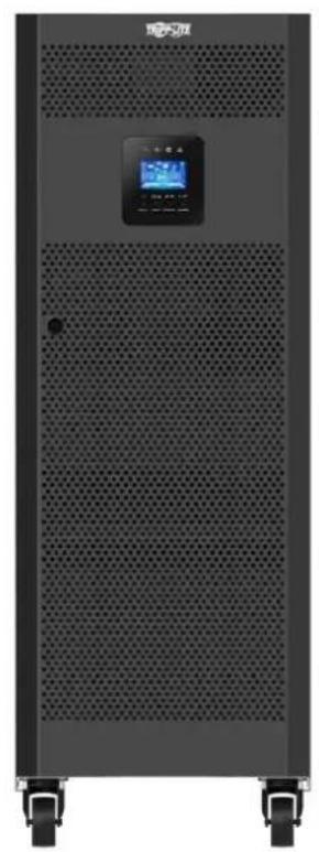


Table of Contents
1. Introduction 3
2. Important SafetyWarnings 4
2.1 UPS LocationWarnings 4
2.2 Equipment Connection Warnings 4
2.3 BatteryWarnings 4
2.4 Transportation and Storage 5
2.5 Preparation 5
2.6 Installation 5
2.7 ConnectionWarnings 5
2.8 Operation 6
2.9 Standards
6
3. Installation and Setup
3.1 Unpacking and Inspection 7
3.2 Internal Battery Connection Procedure for S3M30KX/KXD and S3M40KX/KXD Models
3.3 Installation of Internal Batteries in 10 S3M30KX-NIB/KXD-NIB and S3M40KX-NIB/KXD-NIB Models
3.4 Single UPS Installation 22
3.5UPS Installation for Parallel Systems 24
3.6 External Battery Connection 25
3.7 Dual AC Input Installation 26
4. Operation 27
4.1 Display Button Operation 27
4.2 LED Indicators and LCD Panel 27
4.3 Audible Alarm 29
4.4 Single UPS Operation 29
4.5 ParallelUPSOperation 32
4.6 LCD Panel Abbreviations 34
4.7 Setup Menu 34
4.8 Operating Mode/Status Description 41
4.9 Fault Codes 46
4.10 Warning Indicator 47
4.11 Warning Code 47
5. Communication 48
5.1 SNMP Monitoring Slot 48
5.2 EPO Connector 48
5.3 RS-232 Port 48
5.4 USB Port 48
6.Troubleshooting 49
7. Storage and Maintenance 50
7.1 Storage 50
7.2 Maintenance 50
7.3 Battery 50
7.4 Fan 50
8. Specifications 51
9.Warranty 54
Espanol 55
Françals 109
Pycckn 163
Deutsch 217
1. Introduction
Tripp Lite's SmartOnline S3MKX-Series Uninterruptible Power Supply (UPS) is a Voltage and Frequency Independent (VFI) true on-line, double-conversion 3-phase UPS system. This UPS continuously conditions the incoming electrical power supply, eliminating power disturbances that will otherwise damage sensitive electronic devices and minimising system downtime from power fluctuations and interruptions.
S3MKX-Series UPS systems are designed to the highest quality and performance standards and offer the following features:
| Model Agency Number | Internal Batteries AC | Inputs Capacity | ||
| S3M30KX AG-6030 Yes Single 30kVA | ||||
| S3M30KXD AG-6030 Yes Dual 30kVA | ||||
| S3M30KX -NIB AG-6031 No Single 30kVA | ||||
| S3M30KXD-NIB AG-6031 No Dual 30kVA | ||||
| S3M40KX AG-6040 Yes Single 40kVA | ||||
| S3M40KXD AG-6040 Yes Dual 40kVA | ||||
| S3M40KX -NIB AG-6041 No Single 40kVA | ||||
| S3M40KXD-NIB AG-6041 No Dual 40kVA | ||||
| S3M60KX AG-6060 No Single 60kVA | ||||
| S3M60KXD AG-6060 No Dual 60kVA | ||||
| S3M80KX AG-6080 No Single 80kVA | ||||
| S3M80KXD AG-6080 No Dual 80kVA | ||||
True on-line UPS - the highest level of UPS protection, fully regulates the incoming power with zero transfer time to battery in the event of an extended mains failure, so critical loads remain continuously supported
- Paralleling for capacity and redundancy of up to three UPS systems
- High-efficiency performance in AC On-line and Battery Standby Modes minimise energy consumption
- Market-leading compact footprint, so more power can be provided from smaller spaces
- ECO Mode allows the UPS to operate on bypass in stable utility conditions, and immediately transfers to inverter to support the load when the utility input drops below tolerance
- High output power factor - more actual power allows more equipment to be supported
Automatic and manual bypass increase system reliability and allow for maintenance without removing power from the attached load
- Wide input voltage window - the UPS system regulates even poor-quality incoming power without reverting to battery, maximising system uptime and protecting battery life
- Matching external battery cabinets allow for increased battery autonomy
Emergency shutdown via REPO
SNMP Network Monitoring and Control and Contact-Closure Management cards available
- Optional dual-AC input "KXD" models available
SmartOnline S3MKX-Series UPS systems are ideally suited for protecting 4-wire loads in the following mission-critical electrical applications:
IT infrastructure and data centres
- Edge IT installations
Telecommunications
Networks (LAN/WAN)
Corporate infrastructure
- Security and emergency systems
Financial institutions
Healthcare and hospitals
2. Important SafetyWarnings
SAVE THESE INSTRUCTIONS
This manual contains important instructions and warnings that should be followed during the installation and maintenance of all Tripp Lite SmartOnline S3MX 3-Phase 30kVA, 40kVA, 60kVA and 80kVA UPS Systems and their batteries. Failure to heed these warnings may affect your warranty.
2.1 UPS LocationWarnings
- Install the UPS indoors, away from heat, direct sunlight, dust and excess moisture or other conductive contaminants.
- Install the UPS in a structurally sound area. The UPS is extremely heavy; take care when moving and lifting the unit.
- Only operate the UPS at indoor temperatures between 0°C and 40°C .
- Optimum UPS performance and maximum battery life is obtained when the operating temperature is maintained between 17°C and 25°C .
- Ensure the installation area has sufficient space for maintenance and ventilation of the UPS system. Maintain a minimum clearance of 50 cm from the rear, front and both sides of the UPS for maintenance and ventilation.
- Do not install the UPS near magnetic storage media, as this may result in data corruption.
2.2 Equipment ConnectionWarnings
- Use of this equipment in life support applications where failure of this equipment can reasonably be expected to cause the failure of the life support equipment or to significantly affect its safety or effectiveness is not recommended.
- The UPS system contains its own energy source (battery). The output terminals may be live, even when the UPS is not connected to an AC supply.
The UPS models covered in this manual are not compatible with loads that do not have a Neutral Reference or Delta load.
2.3 BatteryWarnings
This UPS contains LETHAL VOLTAGES. The UPS is designed to supply power, even when disconnected from utility power. Only AUTHORISED SERVICE PERSONNEL should access the interior of the UPS after disconnecting utility and DC power.
Batteries present a risk of electrical shock and burns from high short-circuit current. Battery connection or replacement should be performed only by qualified service personnel, observing proper precautions. Turn off the UPS before connecting or disconnecting internal batteries. Use tools with insulated handles. Do not open the batteries. Do not short or bridge the battery terminals with any object.
The batteries are recyclable. Refer to local codes for disposal requirements or visit triplite.com/support/recycling-program for recycling information.
- Do not dispose of the batteries in a fire, mutilate the batteries or open the battery coverings. Escaping electrolytes may be toxic and cause injury to skin and eyes.
- Do not disconnect the batteries while the UPS is in Battery Mode.
- Disconnect the charging source prior to connecting or disconnecting terminals.
The following precautions should be observed:
1) Remove watches, rings and other metal objects.
2) Use tools with insulated handles.
3) Wear rubber gloves and electrical-grade boots.
4) Use an electrical-grade rubber mat while servicing batteries.
5) Do not lay tools or metal parts on top of batteries or battery cabinets.
6) Determine whether the battery supply (+, -, N) is inadvertently grounded. If it is, remove the source of the ground. Contact with any part of a grounded battery can result in electric shock. The likelihood of an electric shock is reduced if such grounds are removed during installation and maintenance.
- Battery replacement should be performed only by authorised service personnel, using the same number and type of batteries (sealed lead acid).

WARNING: In order to avoid any hazardous conditions during UPS installation and maintenance, these tasks may be performed only by qualified and experienced electricians.
Please read this Owner's Manual and the safety instructions carefully before installing or using the unit.
2. Important SafetyWarnings
2.4 Transportation and Storage
To protect against shock and impact, transport the UPS system only in the original packaging.
The UPS must be stored in a room that is dry and ventilated.
2.5 Preparation
Condensation may occur if the UPS system is moved directly from a cold to a warm environment. The UPS system must be completely dry before being installed. Please allow at least two hours for the UPS system to adjust to the environment.
Do not install the UPS system near water or in moist environments.
Do not install the UPS system in direct sunlight or near heat sources.
Do not block the ventilation holes on the UPS system's housing.
2.6 Installation
Do not connect appliances or devices that could overload the UPS (i.e., equipment with large electrical motors) to the UPS output sockets or terminal.
Carefully arrange cables so no one can step on or trip over them.
Do not block the UPS system's air vents. The UPS must be installed in a location with good ventilation. Ensure adequate ventilation space on each side of the unit.
The UPS contains an earthed terminal. In the final installed system configuration, ensure equipotential earth grounding to the external UPS battery cabinet by connecting the earth terminals of both cabinets together.
The UPS should only be installed by qualified maintenance electrical service personnel.
An appropriate disconnect device such as short-circuit backup protection must be provided in the building wiring installation.
An integral single-emergency switching device should be included in the building wiring installation.
4 Connect the earth ground before connecting to the building wiring terminal.
Installation and wiring must be performed in accordance with local electrical codes and regulations.
2.7 ConnectionWarnings
The UPS system does not contain standard backfeed protection inside. Isolate the UPS before working on this circuit. The isolation device must be able to carry the UPS input current.
- This UPS should be connected with TN earthing system.
- The power supply for this unit must be 3-phase rated in accordance with the equipment nameplate. It also must be suitably grounded.
- The input power to 3-phase UPS models requires a 4-pole breaker.
- Use of this equipment in life support applications where failure of this equipment can reasonably be expected to cause the failure of the life support equipment or to significantly affect its safety or effectiveness is not recommended.
- Connect the UPS power module's grounding terminal to a grounding electrode conductor.
- The UPS is connected to a DC energy source (battery). The output terminals may still be live even when the UPS is not connected to an AC supply.
2. Important SafetyWarnings
When installing the unit, verify that any maintenance bypass panel used is configured correctly before applying power to the unit.
- Be sure to place a warning label on all primary power isolators installed remotely from the UPS area and on any external access points between such isolators and the UPS. The warning label shall carry the following wording or equivalent.
Before working on this circuit
-
Isolate Uninterruptible Power System (UPS)
-
Then check for Hazardous Voltage between all terminals

Risk of Voltage Backfeed
2.8 Operation
Do not disconnect the earth conductor cable on the UPS or the building wiring terminals at any time, as this will cancel the protective earth of the UPS system.
In order to fully disconnect the UPS system, first press the "OFF" button, then disconnect the mains.
Ensure no liquid or other foreign objects can enter into the UPS system.
2.9 Standards
| *Safety | |
| IEC 62040-1: 2008+A1:2013 | |
| *EMI | |
| Conducted Emission......EN 62040-2: 2006 | Category C3 |
| Radiated Emission......EN 62040-2: 2006 C | Category C3 |
| *EMS | |
| ESD......EN 61000-4-2 Level 4 | |
| RS......EN 61000-4-3 Level 3 | |
| EFT......EN 61000-4-4 | Level 4 |
| SURGE......EN 61000-4-5 Level 4 | |
| CS......EN 61000-4-6 | Level 3 |
| Power-Frequency Magnetic Field......EN 61000-4-8 Level 4 | |
| Low-Frequency Signals......EN 61000-2-2 | |
| Warning: This is a product for commercial applications. Installation restrictions or additional precautions may be needed to prevent disturbances. | |
3. Installation and Setup
3.1 Unpacking and Inspection
Unpack the unit and inspect the contents. Packaging may include additional accessories and components, depending on specific customer orders.
One (1) UPS
One (1) Owner's Manual
One (1) RS-232 Cable
- One (1) 1.5 m battery cable kit extension (included with 30K and 40K models only)
Cabling for UPS Paralleling:
One (1) parallel cable (only available for parallel model) for every set of UPS units being paralleled
One (1) shared current cable (only available for parallel model) for every set of UPS units being paralleled
Other Accesory and Component Options Available
Additional Charging Board to increase the battery charger capacity:
- 4A charger boards may be paralleled to increase the charger's current capacity. For more information, refer to ACCESSORIES in section 8. Specifications.
Note: Do not turn on the unit. Make sure to inspect the unit prior to installation. Ensure nothing inside the package was damaged during transportation. Notify the carrier and dealer immediately if there is any damage or missing parts. Please keep the original packaging in a safe place for future use.
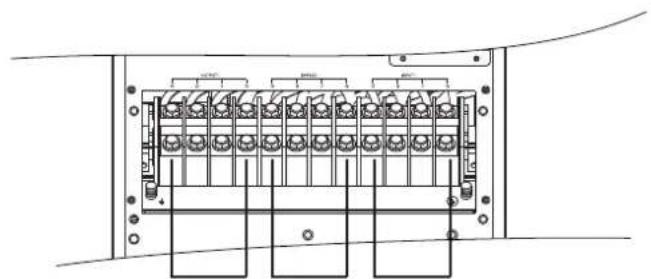
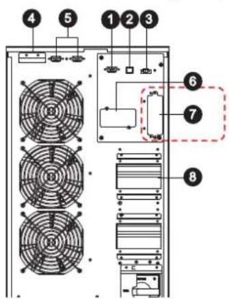
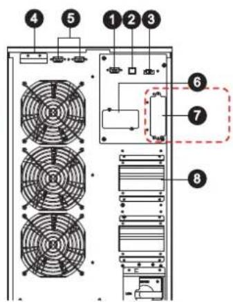
Rear Panel View - 30K and 40K Models
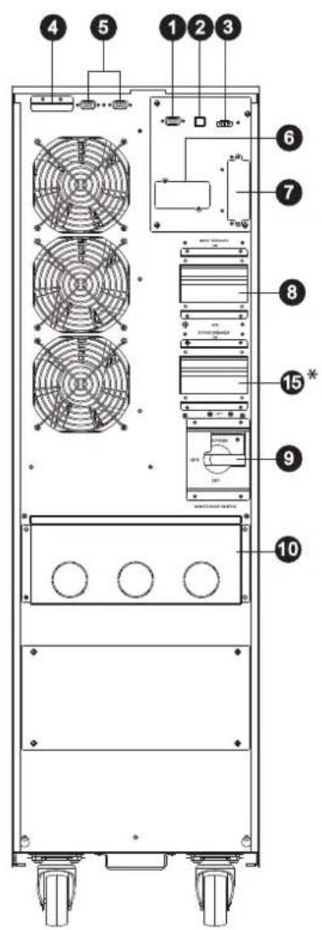
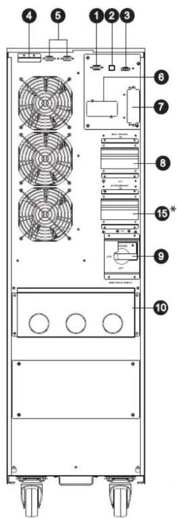
RS-232 Communications Port
2 USB Communications Port
Emergency Power Off (EPO) Connector
4 Share Current Port for Paralleling Units
5 Parallel Ports for Paralleling Units
SNMP Slot for Network Monitoring using (Optional WEBCARDLX)
External Battery Cabinet Connector
8 Input Circuit Breaker
9 Maintenance Bypass Switch (for Service Personnel Use Only)
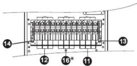
10 Input/Output Terminal (Refer to 11 and 12 for Details)
11 Input Terminal
12 Output Terminal (Connects to Mission-critical Loads)
13 Input Grounding Terminal
14 Output Grounding Terminal
15 Input 2 Circuit Breaker
16 Input 2 Terminal (Bypass Input)
*Input 2 (Bypass Input) and Input 2 Circuit Breaker for "KXD" dual input models only.
30K Rear Panel 40K Rear Panel 30K and 40K Input/Output Terminals
3. Installation and Setup
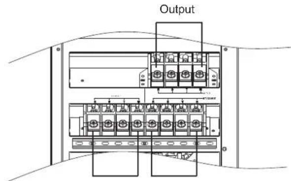
Front Panel View - 60K Model
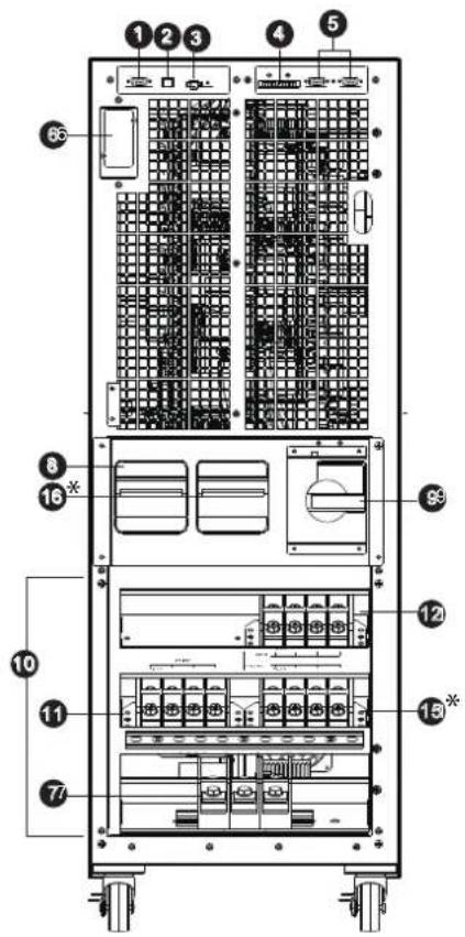
60KXD Front View with Door Open
Front Panel View - 80K Model
80KXD Front View with Door Open
1 RS-232 Communications Port
2 USB Communications Port
Emergency Power Off (EPO) Connector
4 Share Current Port for Paralleling Units
5 Parallel Ports for Paralleling Units
SNMP Slot for Network Monitoring using (Optional WEBCARDLX)
External Battery Cabinet Connector
UPS Input Circuit Breaker
9 Maintenance Bypass Switch (for service personnel use only)
10 Input/Output Terminal (Refer to 11 and 12 for details)
UPS Input Terminal
12 Output Terminal (Connects to Mission-critical Loads)
13 Input Grounding Terminal
14 Output Grounding Terminal
15 Input 2 Terminal (Bypass Input)
16 Input 2 Circuit Breaker
Input 2 (Bypass Input) and Input 2 Circuit Breaker for "KXD" dual input models only.
RS-232 Communications Port
2 USB Communications Port
Emergency Power Off (EPO) Connector
4 Share Current Port for Paralleling Units
5 Parallel Ports for Paralleling Units
SNMP Slot for Network Monitoring using (Optional WEBCARDLX)
External Battery Cabinet Connector
UPS Input Switch
9 Maintenance Bypass Switch (for Service Personnel Use Only)
10 Input/Output Terminal (Refer to 11 and 12 for Details)
Line Input Terminal
12 Output Terminal (Connects to Mission-critical Loads)
13 Input Grounding Terminal
14 Output Grounding Terminal
15 Input 2 Terminal (Bypass Input)
16* Input 2 Switch
Input 2 (Bypass Input) and Input 2 Switch for "KXD" dual input models only.
3. Installation and Setup
3.2 Internal Battery Connection Procedure for S3M30KX, S3M30KXD, S3M40KX, S3M40KXD Models

DANGER! LETHAL HIGH VOLTAGE HAZARD!
Potentially lethal high voltage exists within the batteries, even when not connected to a UPS system. Battery connection should be performed by qualified service personnel only, following all the precautions listed in this manual and adhering to local electrical codes. Refer to section 2.3 BatteryWarnings.
Internal Battery Connection Procedure
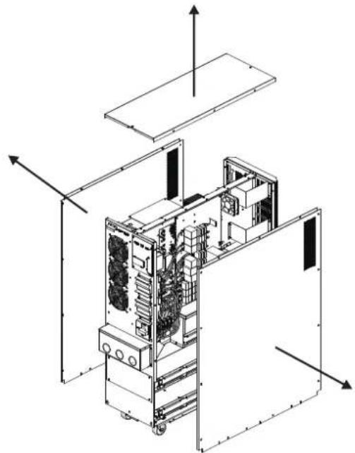
1) Remove all screws labeled 1 (Figure 3.1).
2) Remove top plate, right side and left side plates (Figure 3.2).
See next page for steps 3-5.
Figure 3.1 Figure 3.2
3. Installation and Setup
3) For 30kVA and 40kVA units with internal batteries, there are four battery cable points that are disconnected for shipping purposes (refer to Figures 3.3 and 3.4). These four cables (two on the right side and two on the left side) will need to be reconnected for proper battery cabinet operation.
Figure 3.3 Figure 3.4
4) Re-Install the top and side panels from Step 2.
5) Re-Install and tighten all screws from Step 1 with a torque of 1N· m .
3.3 Installation of Internal Batteries in S3M30KX-NIB, S3M30KXD-NIB, S3M40KX-NIB, and S3M40KXD-NIB Models

DANGERI LETHAL HIGH VOLTAGE HAZARDI
Be careful to observe all safety warnings in the manual, especially those in section 2.3 BatteryWarnings.
Battery installation should be performed by qualified electrical service personnel only.
Items needed:
1) Protective equipment (rubber gloves, electrical rated boots, electrical rated rubber floor mat, etc. as outlined in section 2.3 Battery Warnings).
2) 80x Sealed Lead Acid Batteries: 12V 9Ah (Non-Spillable VRLA AGM/GEL). Batteries must be UL-recognised to UL 1989, UL CCN: BARZ2.
3) Tripp Lite Wiring Kit PN: ACC-0442. Check the wiring kit to make sure all necessary items are there. This kit includes:
| CABLE CABLE LENGTH QUANTITY | ||
| 1 | 75 mm 56 | |
| 2 | 160 mm 4 | |
| 3 | 250 mm 9 | |
| 4 | 350 mm 3 | |
| 5 | 700 mm 2 | |
| 6 | 800 mm 1 | |
| 7 | 930 mm 1 | |
3. Installation and Setup
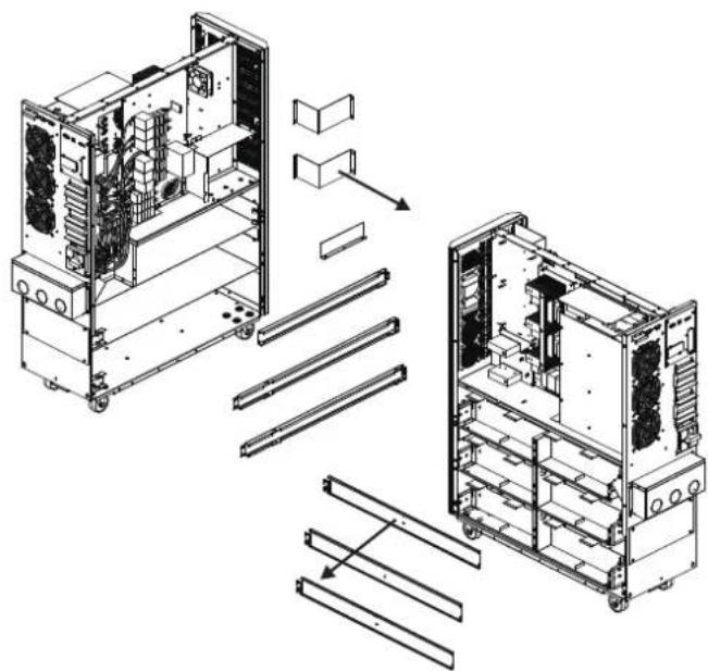
1) Take off top and side panels by removing all screws.
3) Install 11 battery packs to the layer (L1-a). Be sure to keep terminal sides of all batteries up.
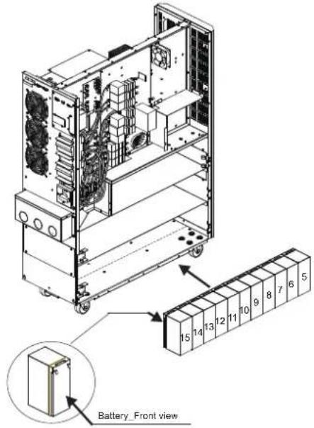
5) Install another 9 battery packs to the layer (L3-a). Be sure to keep terminal sides of all batteries up.
2) Remove the battery bracket bars on the right and left sides of the UPS.
4) Install another 11 battery packs to the layer (L2-a). Be sure to keep terminal sides of all batteries up.
3. Installation and Setup
6) Install another 11 battery packs to the layer (L1-b). Be sure to keep terminal sides of all batteries up.
8) Install another 8 battery packs to the layer (L3-b). Be sure to keep terminal sides of all batteries up.

10) Install another 2 battery packs to the layer (L6). Be sure to keep terminal sides of all batteries down.
7) Install another 11 battery packs to the layer (L2-b). Be sure to keep terminal sides of all batteries up.

9) Install another 5 battery packs to the layer (L4 and L5). Be sure to keep terminal sides of all batteries up.
3. Installation and Setup
11) Reattach the six battery bracket bars removed in step 2.
12) On the right side of the UPS, use 30 pieces of cable to connect two terminals on all batteries shown below.
3. Installation and Setup
13) Use one cable to connect #51 and #52 batteries.
- Use one cable
6 to connect #75 and #76 batteries.
- Use one cable
5 to connect #67 and #68 batteries.
- Use one cable
4 to connect #64 and #65 batteries.
- Use one cable
2 to connect #62 and #63 batteries.
14) On the left side of the UPS, use 26 pieces of cable to connect two terminals on all batteries.
3. Installation and Setup
15) Use one cable 5 to connect #77 and #78 batteries.
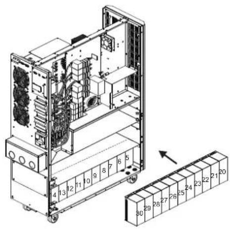
16) Install another 4 battery packs to the layer (L1). Be sure to keep terminal sides of all batteries up.
3. Installation and Setup
17) Use one cable 2 to connect #4 and #5 batteries.
- Use one cable
3 to connect #3 and #4 batteries.
- Use one cable
3 to connect #2 and #3 batteries.
- Use one cable
3 to connect #1 and #2.
18) Install another 4 battery packs to the layer (L2). Be sure to keep terminal sides of all batteries up.

3. Installation and Setup
19) Use one cable 2 to connect #19 and #20 batteries.
- Use one cable
3 to connect #18 and #19 batteries.
- Use one cable
3 to connect #17 and #18 batteries.
- Use one cable
3 to connect #16 and #17 batteries.
- Use one cable
4 to connect #15 and #16 batteries.
20) Install another 4 battery packs to the layer (L3). Be sure to keep terminal sides of all batteries up.

3. Installation and Setup
21) Use one cable to connect #34 and #35 batteries.
- Use one cable
3 to connect #33 and #34 batteries.
- Use one cable
3 to connect #32 and #33 batteries.
- Use one cable
3 to connect #31 and #32 batteries.
- Use one cable
4 to connect #30 and #31 batteries.
22) Reattach the battery brackets.

3. Installation and Setup
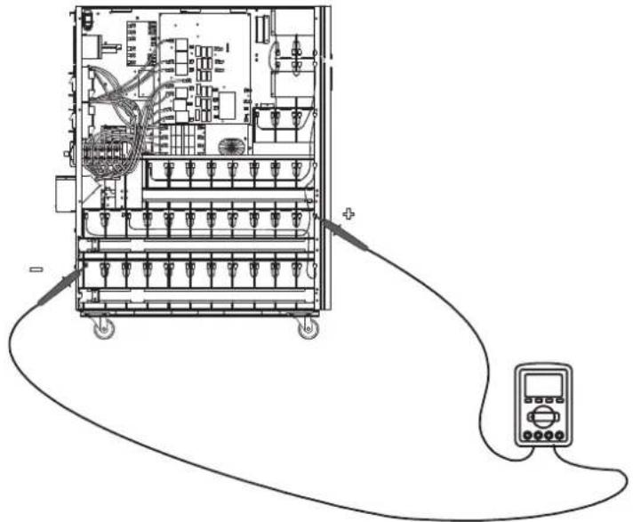
23) Use a meter to measure the positive pole of #20 battery and the negative pole of #1 battery. (DC voltage should be within 240V~270V)
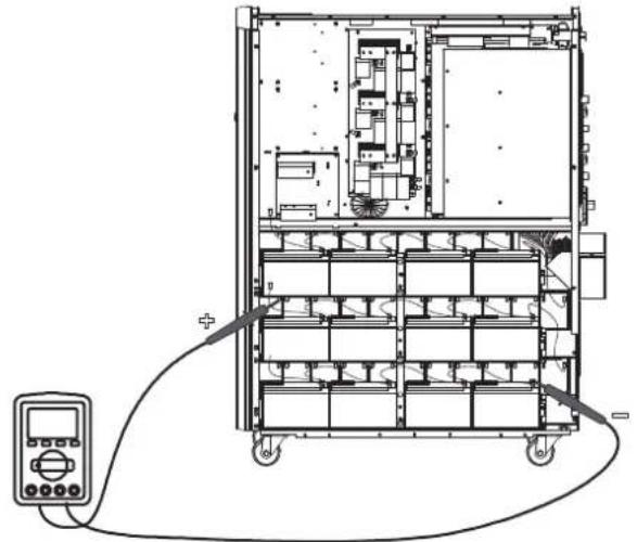
24) Use a meter to measure the positive pole of #40 battery and the negative pole of #21 battery. (DC voltage should be within 240V~270V)
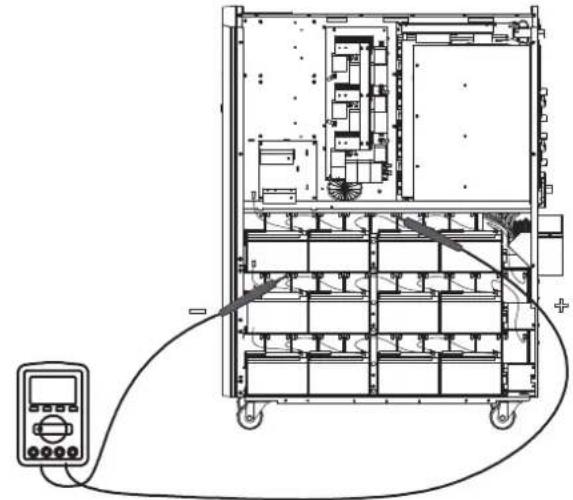
25) Use a meter to measure the positive pole of #80 battery and the negative pole of #61 battery. (DC voltage should be within 240V~270V)
26) Use one meter to measure the positive pole of #60 battery and the negative pole of#41 battery. (DC voltage should be within 240V~270V)
3. Installation and Setup
27) Use the Battery Fuse PCB to connect batteries and refer to the Figures 3.5, 3.6 and 3.7. Refer to Table 3.1 for a complete battery wiring listing.
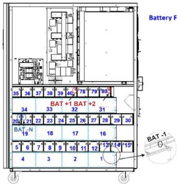
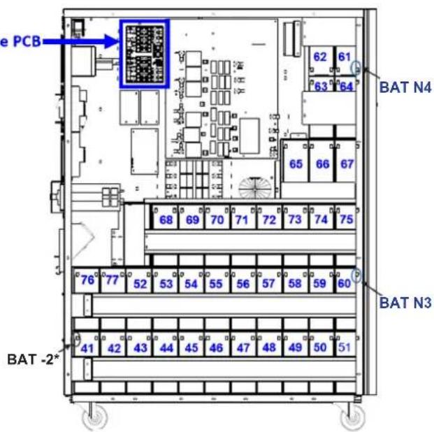
| BAT +1 cable to positive pole of #40 battery. BAT -1 cable to negative pole of #1 battery. | |
| BAT +2 cable to positive pole of #80 battery. | BAT -2 cable to negative pole of #41 battery.* |
| BAT N1 cable to positive pole of #20 battery. | BAT N2 cable to negative pole of #21 battery. |
| BAT N3 cable to positive pole of #60 battery. | BAT N4 cable to negative pole of #61 battery. |
Left Side S3M30KX/S3M30KXD S3M40KX/S3M40KXD
Right Side S3M30KX/S3M30KXD S3M40KX/S3M40KXD
* Only the BAT -2 cable and connector is routed through the cable grommet.
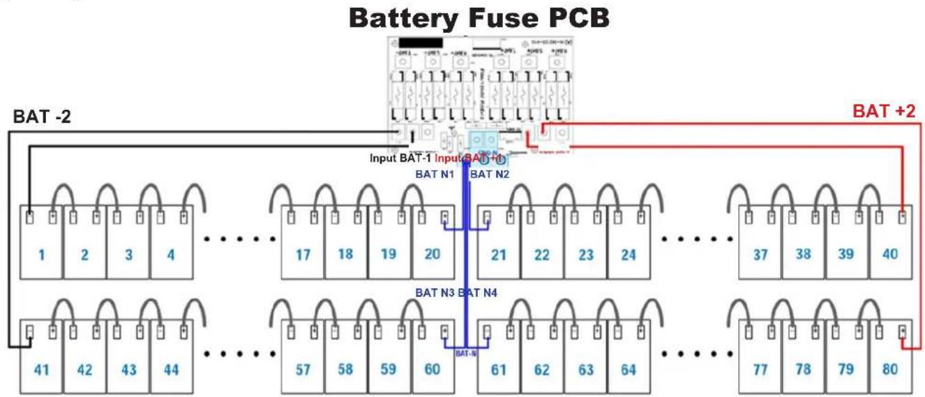
Figure 3.5 Figure 3.6
Figure 3.7
Notes:
The blue numbers in above figures are "Battery Numbers" from 1 to 80, which are used for battery position identification.
- There are 2 red wires, 2 black wires and 4 blue wires, which connect the battery fuse board and batteries.
- S3M30KX/KXD/NIB battery fuse board part number: 71-303365-XXG.
- S3M40KX/KXD/NIB battery fuse board part number: 71-303366-XXG.
3. Installation and Setup
Table 3.1 Battery Wiring for S3M30KX/KXD/NIB and S3M40KX/KXD/NIB
| BATNumber 1 | 2345678910 | |||||||||||||||||||
| Terminal | - | + | - | + | - | + | - | + | - | + | - | + | - | + | - | + | - | + | - | + |
| Connection Wire | 1050 mm Black Wire | 250 mm Wire | 250 mm Wire | 250 mm Wire | 160 mm Wire | 75 mm Wire | 75 mm Wire | 75 mm Wire | 75 mm Wire | 75 mm Wire | See Below | |||||||||
| BATNumber 10 11 12 13 14 15 16 17 18 19 | ||||||||||||||||||||||
| Terminal | - | + | - | + | - | + | - | + | - | + | - | + | - | + | - | + | - | + | - | + | - | + |
| Connection Wire | 75 mm Wire | 75 mm Wire | 75 mm Wire | 75 mm Wire | 75 mm Wire | 350 mm Wire | 250 mm Wire | 250 mm Wire | 250 mm Wire | See Below | ||||||||||||
| BAT Number | 19 | 20 | 21 | 22 | 23 | 24 | 25 | 26 | 27 | 28 | ||||||||||
| Terminal | - | + | - | + | - | + | - | + | - | + | - | + | - | + | - | + | - | + | - | + |
| Connection Wire | 160 mm Wire | 1350 mm Blue Wire from Fuse Holder | 1350 mm Blue Wire from Fuse Holder | 75 mm Wire | 75 mm Wire | 75 mm Wire | 75 mm Wire | 75 mm Wire | 75 mm Wire | 75 mm Wire | See Below | |||||||||
| BAT Number | 28 | 29 | 30 | 31 | 32 | 33 | 34 | 35 | 36 | 37 | ||||||||||
| Terminal | - | + | - | + | - | + | - | + | - | + | - | + | - | + | - | + | - | + | - | + |
| Connection Wire | 75 mm Wire | 75 mm Wire | 350 mm Wire | 250 mm Wire | 250 mm Wire | 250 mm Wire | 160 mm Wire | 75 mm Wire | 75 mm Wire | See Below | ||||||||||
| BAT Number | 37 | 38 | 39 | 40 | ||||
| Terminal | - | + | - | + | - | + | - | + |
| Connection Wire | 75 mm Wire | 75 mm Wire | 75 mm Wire | 1050 mm Red Wire from Fuse Holder | ||||
| BAT Number | 41 | 42 | 43 | 44 | 45 | 46 | 47 | 48 | 49 | 50 | ||||||||||
| Terminal | - | + | - | + | - | + | - | + | - | + | - | + | - | + | - | + | - | + | - | + |
| Connection Wire | 900 mm BlackWire from Fuse Holder | 75 mm Wire | 75 mm Wire | 75 mm Wire | 75 mm Wire | 75 mm Wire | 75 mm Wire | 75 mm Wire | 75 mm Wire | 75 mm Wire | See Below | |||||||||
| BATNumber 50 51 52 53 54 55 56 57 58 59 | ||||||||||||||||||||||
| Terminal | - | + | - | + | - | + | - | + | - | + | - | + | - | + | - | + | - | + | - | + | - | + |
| Connection Wire | 75 mm Wire | 800 mm Wire | 75 mm Wire | 75 mm Wire | 75 mm Wire | 75 mm Wire | 75 mm Wire | 75 mm Wire | 75 mm Wire | 75 mm Wire | See Below | |||||||||||
| BAT Number | 59 | 60 | 61 | 62 | 63 | 64 | 65 | 66 | 67 | 68 | ||||||||||
| Terminal | - | + | - | + | - | + | - | + | - | + | - | + | - | + | - | + | - | + | - | + |
| Connection Wire | 75 mm Wire | 1350mm Blue Wire from Fuse Holder | 1150mm Blue Wire from Fuse Holder | 75 mm Wire | 160 mm Wire | 75 mm Wire | 350 mm Wire | 75 mm Wire | 75 mm Wire | 700 mm Wire | See Below | |||||||||
| BAT Number | 68 | 69 | 70 | 71 | 72 | 73 | 74 | 75 | 76 | 77 | ||||||||||
| Terminal | - | + | - | + | - | + | - | + | - | + | - | + | - | + | - | + | - | + | - | + |
| Connection Wire | 75 mm Wire | 75 mm Wire | 75 mm Wire | 75 mm Wire | 75 mm Wire | 75 mm Wire | 75 mm Wire | 930 mm Wire | 75 mm Wire | See Below | ||||||||||
| BAT Number | 77 | 78 | 79 | 80 | ||||
| Terminal | - | + | - | + | - | + | - | + |
| Connection Wire | 700 mm Wire | 75 mm Wire | 75 mm Wire | 850 mm Red Wire from Fuse Holder | ||||
28) Reinstall the top and side panels per step 1). Tighten all screws with a torque of 1N· m .
3. Installation and Setup
3.4 Single UPS Installation
Installation and wiring must be performed in accordance with local electrical codes/regulations and should only be performed by qualified personnel.
1) Make sure the mains wire and breakers in the building can sustain the rated capacity of the UPS to avoid electric shock or fire hazard.
Note: Using a wall receptacle as the input power source for the UPS may result in the receptacle burning or being destroyed.
2) Switch off the mains switch in the building prior to installation.
3) Turn off all the connected devices before connecting to the UPS.
4) Prepare the power cables according to Table 3.2. Refer to Table 3.3 for UPS Input Breaker sizes and Table 3.4 for Battery Cabinet Batteries and Breaker sizes.

WARNING:
- Before connecting any wires, make sure the AC input and battery power are completely shut off.
Table 3.2 Power Cables
| Model | Wiring Specification | GroundInput | ||||
| S3M30KX/KXD 8 | AWG [8 mm 2] | 8 AWG [8 mm 2] | 4 AWG [21 mm 2] | N/A, when using only internal batteries 4 AWG [21 mm 2] | [21 mm 2] | |
| S3M30KX/KXD 8 | AWG [8 mm 2] | 8 AWG [8 mm 2] | 4 AWG [21 mm 2] | 4 AWG [21 mm 2], for external battery pack | 4 AWG [21 mm 2] | |
| S3M30KX-NIB S3M30KXD-NIB | 8 AWG [8 mm 2] | 8 AWG [8 mm 2] | 4 AWG [21 mm 2] | 4 AWG [21 mm 2], for external battery pack | 4 AWG [21 mm 2] | |
| S3M40KX/KXD 6 | AWG [13 mm 2] | 6 AWG [13 mm 2] | 4 AWG [21 mm 2] | N/A, when using only internal batteries 4 AWG [21 mm 2] | [21 mm 2] | |
| S3M40KX/KXD 6 | AWG [13 mm 2] | 6 AWG [13 mm 2] | 4 AWG [21 mm 2] | 4 AWG [21 mm 2], for external battery pack | 4 AWG [21 mm 2] | |
| S3M40KX-NIB S3M40KXD-NIB | 6 AWG [13 mm 2] | 6 AWG [13 mm 2] | 4 AWG [21 mm 2] | 4 AWG [21 mm 2], for external battery pack | 4 AWG [21 mm 2] | |
| S3M60KX/KXD 4 | AWG [21 mm 2] | 4 AWG [21 mm 2] | 1 AWG [42.4 mm 2] | 1 AWG [42.4 mm 2] | 4 AWG [21 mm 2] | |
| S3M80KX/KXD 2 | AWG [34 mm 2] | 2 AWG [34 mm 2] | 1/0 AWG [54 mm 2] | 1/0 AWG [54 mm 2] | 2 AWG [34 mm 2] | |
Table 3.3 UPS Input Breakers
| Model (Agency Number) | Breaker Size |
| S3M30KX (AG-6030) | 63A, 3-Pole |
| S3M30KXD (AG-6030) | 63A, 3-Pole |
| S3M30KX-NIB (AG-6031) | 63A, 3-Pole |
| S3M30KXD-NIB (AG-6031) | 63A, 3-Pole |
| S3M40KX (AG-6040) | 80A, 3-Pole |
| S3M40KXD (AG-6040) | 80A, 3-Pole |
| S3M40KX-NIB (AG-6041) | 80A, 3-Pole |
| S3M40KXD-NIB (AG-6041) | 80A, 3-Pole |
| S3M60KX (AG-6060) | 150A, 3-Pole |
| S3M60KXD (AG-6060) | 150A, 3-Pole |
| S3M80KX (AG-6080) | 6 x 30A Fuses/Phase |
| S3M80KXD (AG-6080) | 6 x 30A Fuses/Phase |
Table 3.4 Battery Cabinet Batteries and Breakers
| Model | Batteries Included | Battery Size and Qty. | Breaker Size |
| BP480V100 | Yes | 100Ah x 40 | 400A, 3-Pole |
| BP480V65 | 65Ah x 40 | 300A, 3-Pole | |
| BP480V40 | 40Ah x 40 | 200A, 3-Pole | |
| BP480V100-NIB | No | (Designed For) 100Ah x 40 | 400A, 3-Pole |
| BP480V65-NIB | (Designed For) 65Ah x 40 | 300A, 3-Pole | |
| BP480V40-NIB | (Designed For) 40Ah x 40 | 200A, 3-Pole | |
| BP480V10 | Yes | 10Ah x 80 | 100A (Fuse) |
| BP480V09 | 9Ah x 80 | 100A (Fuse) | |
| BP480V10-NIB | No | (Designed For) 10Ah/9Ah x 80 | 100A (Fuse) |
Notes:
- The S3M30FX/FXD/NIB cable should be able to withstand over 63A current. It is recommended to use 8 AWG (8 mm²) or thicker wire for Phase and 4 AWG (21 mm²) or thicker wire for Neutral for safety and efficiency.
- The S3M40KX/KXD/NIB cable should be able to withstand over 80A current. It is recommended to use 6 AWG (13 mm²) or thicker wire for Phase and 4 AWG (21 mm²) or thicker wire for Neutral for safety and efficiency.
- The S3M60KX/KXD cable should be able to withstand over 122A current. It is recommended to use 4 AWG (21 mm²) or thicker wire for Phase and 1 AWG (42 mm²) or thicker wire for Neutral for safety and efficiency.
- The S3M80KX/KXD cable should be able to withstand over 160A current. It is recommended to use 2 AWG (34 mm²) or thicker wire for Phase and 1/0 AWG (54 mm²) or thicker wire for Neutral for safety and efficiency.
3. Installation and Setup
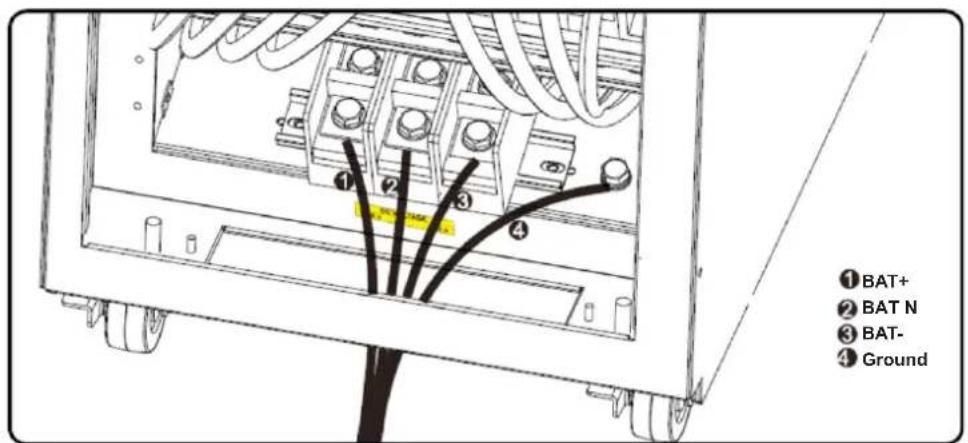
5) Remove the terminal block cover to access the UPS system's input, output and grounding connection terminals. Then connect the wires according to the terminal block diagram shown below. Connect the grounding/earthing wires first when making other wire connections.
Notes:
- Ensure the wires are tightly and securely connected to the terminals.
- Install the output breaker between the output terminal and the load. The breaker should be qualified with leakage current protective function.
Cabling should be protected by flexible conduit and routed through the appropriate knockouts in the terminal block cover.
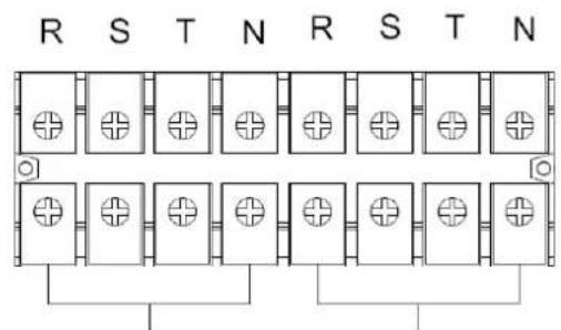
Output OutputInput Input
Single Input Terminal Block Wiring Diagram for S3M60K and S3M80K
Single Input Terminal Block Wiring Diagram for S3M30KX and S3M40KX
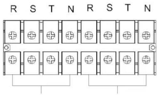
Output Input 2 Input 2Input Input
Dual Input Terminal Block Wiring Diagram for S3M30KXD and S3M40KXD
Dual Input Terminal Block Wiring Diagram for S3M60KXD and S3M80KXD
BAT+BAT-N BAT-
±240V Battery Connection Wiring
Note: Be sure to also add an equipotential bonding wire between the UPS and the External Battery Cabinets.
6) Re-attach the terminal block cover to the rear panel of the UPS.
3. Installation and Setup

WARNING:
Make sure the UPS is not turned on prior to installation. The UPS should not be turned on until all wiring has been completed and checked.

WARNING:
If an external battery pack is installed, switch off the battery breaker before installation.
Note: Set the battery pack breaker in the "OFF" position, then install the battery pack.
- Pay close attention to the rated battery voltage posted on the rear panel. Connecting battery packs with the incorrect voltage may cause permanent damage to the UPS.
- Pay close attention to the polarity markings on the external battery terminal block and make sure the correct battery polarity is connected. Wrong connection may cause permanent damage to the UPS.
- Ensure the protective earth ground wiring is correct. The wire current spec, colour, position, connection and conductance reliability should be carefully observed.
- Ensure the utility input and output wiring is correct. The wire current spec, colour, position, connection and conductance reliability should be checked carefully. Make sure the R, S, T and N wiring is correct, not reversed and not short-circuited.
3.5 UPS Installation for Parallel Systems

WARNING:
Installation and wiring must be performed in accordance with the local codes/regulations and installed using the following instructions by a qualified electrical service technician only.
If the UPS is only used for single operation, you may skip this section and proceed to section 3.7.
1) Parallel configuration supports up to three UPS systems. Do not attempt to link more than three UPS systems via parallel configuration.
2) Install and wire the UPS system according to section 3.5 guidelines.
3) When installing the parallel system, the length of input wires (R, S, T, N) in one UPS must be equal to the input wires of the other UPS. Likewise, the length of output wires (R, S, T, N) must also be in equal length. If not, it will cause unbalance current on the output load.
4) Connect the input wiring of each UPS to an input breaker.
5) Connect all input breaker wiring to a main input breaker.
6) Connect the output wiring of each UPS to an output breaker.
7) Connect all output breakers to a main output breaker. This main output breaker will directly connect to the loads.
8) If an external battery pack is used, each UPS must be connected to an independent battery pack or a common battery pack.
Note: The parallel system cannot use a common external battery pack. Doing so will cause permanent damage to the entire system.
9) Refer to the following wiring diagram for parallel installation:
Wiring Diagram of Parallel System (S3M30KX, S3M30KXD, S3M40KX, S3M40KXD, S3M30KX/KXD/NIB and S3M40KX/KXD/NIB Models)
3. Installation and Setup
Wiring Diagram of Parallel System (S3M60KX/KXD and S3M80KX/KXD Models)
3.6 External Battery Connection
The S3M30KX/S3M30KXD and S3M40KX/S3M40KXD UPS models include a robust internal battery system. The S3M60KX and S3M80KX models require external battery packs. External battery packs may be used with all models to extend runtime. Adding external batteries will increase runtime and require additional recharge time.*
The illustrations below show the location of the UPS system's external battery connector for the 30K and 40K model where the battery pack connects. The illustration at the bottom shows the connection for the 60K and 80K models. Follow the installation instructions for your battery pack as they appear in your battery pack Owner's Manual. Ensure the cables are fully inserted into their connectors. Small sparks may occur during battery connection; this is normal.
Do not connect or disconnect battery packs when the UPS is running on battery power.
*Limit three external battery packs per UPS.
External Battery Connector for the S3M30KX/KXD/NIB and S3M40KX/KXD/NIB Models
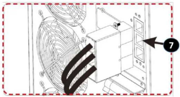
S3M30KX/KXD/NIB and S3M40KX/KXD/NIB External Battery Connection
S3M60KX/KXD and S3M80KX/KXD External Battery Connection
3. Installation and Setup
3.7 Dual AC Input Installation
Dual AC Input UPS (or suffix "KXD") models are defaulted to a Single AC Input configuration via the placement of three shorting jumpers between AC Input 1 and AC Input 2. If you desire to operate the "KXD" models in a dual AC configuration, remove these three jumpers, and wire AC input 1 and AC Input 2 accordingly.
Jumper on "KXD" dual-AC input models. Note: Input neutrals are tied together internally.
4. Operation
4.1 Display Button Operation
| Button Function | |
| ON/Enter Button | Turn on the UPS: Press and hold for more than 0.5 seconds to turn on the UPS. Enter Button: Press to confirm a selection in the settings menu. |
| OFF/ESC Button | Turn off the UPS: Press and hold for more than 0.5 seconds to turn off the UPS. Esc Button: Press to return to the previous menu in the settings menu. |
| Test/Up Button | Battery Test: Press and hold for more than 0.5 seconds to test the battery while in On-line Mode and Freq. Converter* Mode. UP Button: Press to display the next selection in the settings menu. |
| Mute/Down Button | Mute the alarm: Press and hold for more than 0.5 seconds to mute the alarm. Refer to section 4.4.9 for details. Down Button: Press to display the previous selection in the settings menu. |
| Test/Up + Mute/Down Button | Press and hold the two buttons simultaneously for more than 1 second to enter/exit the setup menu. Refer to section 4.7 Setup Menu for details. |
- Freq. Converter means Constant Output Voltage and Constant Output Frequency.
4.2 LED Indicators and LCD Panel
LED Indicators:
There are four LEDs on front panel to show the UPS operation status:
| Mode / LED Line Bypass | Battery Fault | |||
| Initialization ···· | ||||
| Standby Mode o o o o | ||||
| Bypass Mode o · o o | ||||
| On-line Mode · o o o | ||||
| Battery Mode o o · o | ||||
| Freq. Converter* Mode · o o | ||||
| Battery test ····o | ||||
| ECO Mode | ···o o | |||
| Fault | o o o · |
Note: means LED is glowing, and o means LED is off.
4. Operation
LCD Panel
| Display Function | |
| Backup time information | |
| Indicates the battery discharge time in numbers H: hours, M: minutes, S: seconds | |
| Fault and Warning information | |
| Indicates a Warning when this icon is flashing and a Fault when this icon is steady. | |
| When the Fault and Warning Icon is steady, refer to the Fault code description in section 4.9. When the icon is flashing, refer to the Warning code description in section 4.11. | |
| Mute operation | |
| Indicates the UPS alarm is disabled. | |
| Output & Battery voltage information | |
| Indicates the output voltage, frequency or battery voltage. VAC: Output Voltage, VDC: Battery Voltage, Hz: Frequency | |
| Load information | |
| Indicates the load level by 0-25%, 26-50%, 51-75%, and 76-100%. | |
| Indicates overload. | |
| Indicates the load or the output is short. | |
| Mode operation information | |
| Indicates the UPS is connected to the mains. | |
| Indicates the battery is working. | |
| Indicates the bypass circuit is working. | |
| Indicates ECO Mode is enabled. | |
| Indicates the inverter circuit is working. | |
| Indicates the output is working. | |
4. Operation
| Battery information | |
| 100% 75% 36% 25% BATTERY | Indicates the battery capacity by 0-25%, 26-50%, 51-75% and 76-100%. |
| BATFALUT | Indicates the battery is not connected. |
| LOW BATF | Indicates low battery level and low battery voltage. |
| Input & Battery voltage information | |
| VAC: Input Voltage, VDC: Battery Voltage, Hz: Input Frequency | |
4.3 Audible Alarm
| Description Alarm Status Mutable | ||
| UPS Status | ||
| Bypass Mode Beeps once every 2 minutes. | YesBattery Mode Beeps once every 4 seconds. | |
| Fault Mode Beeps continuously. | ||
| Warning | ||
| Overload Beeps twice per second. | No | |
| All other warnings Beeps once per second. | ||
| Fault | ||
| All Beeps continuously. Yes | ||
4.4 Single UPS Operation
4.4.1 Turning On the UPS (On-line Mode)
1) Make sure the power supply is correctly connected.
2) If you have an external battery pack, set the breaker of the battery pack to the "ON" position.
3) Switch the UPS Input breaker/switch (and Input 2 breaker/switch for dual mode models) to the "ON" position. At this time, the fan will be running and the UPS will proceed to power-on for initialization. Several seconds later, the UPS will operate in Bypass Mode and supply power to the connected loads via the bypass.
Note: In Bypass Mode, the load is not protected by the UPS. To protect connected devices, turn on the UPS as shown in Step 2.
4) Press and hold the "ON" button for 0.5 seconds to turn on the UPS. The alarm will beep once.
5) A few seconds later, the UPS will enter On-line Mode. If utility power is abnormal, the UPS will operate in Battery Mode without interruption.
Note: When the UPS is running low on battery power, it will automatically shut down in Battery Mode. The UPS will auto restart in On-line Mode once utility power is restored.
4.4.2 Turning On the UPS without Utility Power (Battery Mode)
1) When using an external battery pack, make sure the two battery strings are correctly connected before switching the battery pack breaker to the "ON" position.
2) Switch the battery pack breaker to the "ON" position.
3) Press the "ON" button to set up the power supply for the UPS. The UPS will enter Power-on Mode. After initialization, the UPS will enter "No Output Mode"/Standby Mode. When this happens, press and hold the "ON" button for 0.5 seconds to turn on the UPS. The alarm will beep once.
4) A few seconds later, the UPS will turn on and enter Battery Mode.
5) Switch the UPS Input breaker/switch (and Input 2 breaker/switch for dual models) to the "ON" position when utility power is restored and verified OK.
4. Operation
4.4.3 Connecting Devices to UPS
1) After the UPS has been turned on, devices may be connected and powered on one at a time. The UPS system's LCD panel will display the total load level.
2) When connecting devices with inductive loads (such as a printer), the in-rush current should be calculated carefully to confirm it meets the capacity of the UPS. Power consumption of such loads may cause an overload.
3) If the UPS is overloaded, the alarm will beep twice every second.
4) In case of overload, remove non-essential devices immediately. To prevent overload and ensure system safety, it is recommended to have the total load connected to the UPS at no more than 80% of its nominal power capacity.
5) If the overload time is higher than the acceptable time listed in On-line Mode, the UPS will automatically transfer to Bypass Mode. After the overload is removed, the UPS will return to On-line Mode. If the overload time is higher than the acceptable time listed in Battery Mode, the UPS will go to fault status. At this time, if the bypass is enabled, the UPS will supply power to the load via bypass. If the bypass function is disabled or the input power is not within acceptable bypass range, it will directly cut off output.
4.4.4 Charging the Batteries
1) After the UPS is connected to utility power, the charger will automatically charge the batteries (except when in Battery Mode, during a battery self-test, overload or when the batteries are fully charged).
2) It is recommended to charge the batteries at least 10 hours prior to use. Otherwise, the backup time may be shorter than expected.
4.4.5 Battery Mode Operation
1) The default value is 990 minutes, or 16.5 hours. The UPS will automatically shut down to protect the battery after discharging for 16.5 hours. This battery discharge protection can be enabled or disabled through the LCD control panel (refer to section 4.7 for more information).
4.4.6 Testing the Batteries
1) To check the battery status when the UPS is in On-line Mode/Freq. Converter Mode, press the "Test" button for the UPS to perform a battery self-test.
2) Users may set battery self-tests through the network management card.
4.4.7 Turning Off the UPS with Utility Power Present in On-line Mode

WARNING: The UPS system shutdown procedure will eliminate AC power output for all loads. Before shutdown, confirm all power loads are turned off.
1) Turn off the UPS inverter by pressing the "OFF" button for at least 0.5 seconds. The alarm will beep once and the UPS will enter Bypass Mode.
Notes:
If the UPS has been set to bypass output, it will bypass voltage from utility power to the output terminal, even though the UPS inverter has been turned off.
After turning off the UPS, be aware that the UPS is operating in Bypass Mode and there is risk of power loss for connected devices.
2) In Bypass Mode, UPS output voltage is still present. In order to cut off the output, switch off the UPS Input breaker/switch (and Input 2 breaker switch for dual mode models). Within a few seconds, the unit's LCD panel will be blank and the UPS will be completely off.
4.4.8 Turning off the UPS with No Utility Power Present in Battery Mode
1) Turn off the UPS by pressing the "OFF" button for at least 0.5 seconds. The alarm will sound once.
2) The UPS will cut off power to output and the LCD panel will be blank.
3) Switch off the UPS Input breaker/switch (and Input 2 breaker/switch for dual mode models)
4.4.9 Muting the Alarm
1) To mute the alarm, press the "Mute" button for at least 0.5 seconds. If the Mute button is pressed after the alarm is muted, the alarm will reactivate.
2) Some warning alarms cannot be muted unless the error is fixed. Refer to section 4.3 for details.
4.4.10 Operation in Warning Status
1) When the Fault LED flashes and the alarm sounds once every second, the UPS is encountering problems with its operation. Users may view the warning indicator from the LCD panel. Check the troubleshooting table in section 6 for more information.
2) Some warning alarms cannot be muted until the error is fixed. Refer to section 4.3 for details.
4. Operation
4.4.11 Operation in Fault Mode
1) When the Fault LED illuminates and the alarm sounds continuously, there is a fatal error in the UPS. Users can view the fault code from the LCD panel. Refer to the table in section 6. Troubleshooting for more information.
2) Check the loads, wiring, ventilation, utility, battery, etc. after a fault occurs. Do not attempt to turn on the UPS again until the problem is resolved. If the problem cannot be fixed, please contact Tripp Lite Tech Support.
3) In the event of an emergency, immediately cut off the utility connection, external battery, and output to avoid further risk or danger.
4.4.12 Transfer Critical Load from Line Mode to Maintenance Bypass

WARNING: This operation should only be performed by maintenance personnel or qualified technicians. When the UPS needs to be repaired or serviced and the load cannot be shut off, the UPS should be put in Maintenance Mode (repairs limited; some repairs may require the unit to be shutdown and power disconnected).
1) Remove the cover of the Maintenance Bypass Switch.
2) Confirm the UPS is operating in Bypass Mode.
3) Turn the Maintenance Bypass Switch to the "BYPASS" position.
4) Turn off the UPS Input Breaker/Switch (for dual input models turn off both the UPS Input Breaker/Switch and the Input 2 Breaker/ Switch).
5) The UPS will enter Shutdown Mode and will slowly de-energise. After the UPS powers off, turn off the battery breaker (external battery cabinet).
6) The critical load is now supported in Maintenance Bypass Mode.
4.4.13 Transfer Critical Load from Maintenance Bypass to Line Mode

WARNING: This operation should only be performed by maintenance personnel or qualified technicians.
1) Turn on the battery breaker (external battery cabinet).
2) Turn on the UPS Input Breaker/Switch (for dual input models turn on both the UPS Input Breaker/Switch and the Input 2 Breaker/ Switch).
3) Confirm the UPS is operating in Bypass Mode.
4) Turn the Maintenance Bypass Switch to the "UPS" position.
5) Install the cover of the Maintenance Bypass Switch.
6) Press Power ON/OFF button for 2 seconds until a beep is heard, then release to start the inverter.
7) The critical load is now supported in Line Mode.
4. Operation
4.5 Parallel UPS Operation
4.5.1 Parallel System Initial Startup
Note: This procedure should be performed only by qualified service personnel.
Before initial startup, ensure all UPS systems have the same configuration and can be connected in parallel.
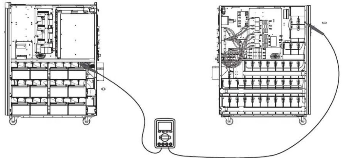
1) Turn on each UPS to On-line Mode (refer to section 4.4.1). Using a multimeter, measure the inverter output voltage of each phase for each UPS to confirm that the inverter voltage difference between actual output and setting value is less than 1.5V (typically 1V). If the difference is greater than 1.5V , calibrate the voltage by configuring the inverter voltage adjustment (refer to Program Codes 15, 16 and 17, in section 4.7) in the LCD setting. If the voltage difference after calibration remains greater than 1.5V , contact Tripp Lite Technical Support for further assistance.
2) Calibrate the output voltage measurement by configuring the output voltage calibration (refer to Program Codes 18, 19, and 20, in section 4.7) in the LCD panel to ensure the difference between the real output voltage and the detected value of the UPS is less than 1V.
3) Turn off each UPS (refer to section 4.4.7), then follow the wiring procedure in section 3.4.
4) Remove the metal cover to access the parallel communication ports on the UPS. Connect each UPS one at a time (maximum of three units for parallel installation) with the parallel cable and shared current cable. Follow the parallel communication cable configuration in the figure below, then reinstall the metal cover.
4.5.2 Turning On a Parallel System in On-line Mode
1) Confirm the Maintenance Bypass Switch of each UPS is in the "UPS" position.
2) Turn on the battery breaker (external battery cabinet) of each UPS.
3) Turn on the UPS Input Breaker/Switch of each UPS (for dual input models turn on both the UPS Input Breaker/Switch and the Input 2 Breaker/Switch).
4) When all UPS systems enter Bypass Mode, measure the output voltage between two UPS systems for the same phase to ensure the phase sequence is correct. If these two voltage differences are near zero, then all connections are correct. If not, check to see if the.
wirings are connected correctly.
5) Turn on each UPS one at a time. Press the Power ON/OFF button for 2 seconds until a beep is heard, then release to start the inverter on each UPS.
6) The UPS systems will then enter On-line Mode synchronously. The parallel system is completed.
4. Operation
4.5.3 Turning on the Parallel System in Battery Mode
1) Confirm the Maintenance Bypass Switch of each UPS is in the "UPS" position.
2) Turn on the battery breaker (external battery cabinet) of each UPS.
Note: UPS may share the same battery bank or use separate battery banks while in a parallel system.
3) Turn on any UPS. Press Power ON/OFF button for 2 seconds until a beep is heard, then release to start the inverter. A few seconds later, the UPS will enter Battery Mode.
4) Turn on another UPS. Press Power ON/OFF button for 2 seconds until a beep is heard, then release to start the inverter. A few seconds later, the UPS will enter Battery Mode and add to the parallel system.
5) If there is a third UPS in the setup, follow the same procedure as outlined above.
6) Turn on the UPS Input Breaker/Switch of each UPS (for dual input models turn on both the UPS Input Breaker/Switch and the Input 2 Breaker/Switch) when utility power is restored and verified OK.
7) The parallel system is complete.
4.5.4 Adding a New Unit to the Parallel System
Note: It is recommended this procedure be performed by only qualified service personnel.
1) A new unit cannot be added to the parallel system when the whole system is in operation. The load must be powered off and the UPS system shut down.
2) Make sure all UPS systems can be connected in parallel. Follow the wiring instructions in section 3.4.
4.5.5 Removing a Unit from the Parallel System
Note: It is recommended this procedure be performed by only qualified service personnel.
There are two methods to remove a unit from the parallel system:
Method 1: Isolating a single unit from a parallel system
1) Turn the Maintenance Bypass Switch to the "OFF" positon.
2) Press the "OFF" key twice, each time for more than 0.5 seconds. The UPS will enter into Bypass Mode or Standby Mode without output.
3) Turn Off the UPS Input Breaker/Switch (for dual input models turn off both the UPS Input Breaker/Switch and the Input 2 Breaker/ Switch).
4) The UPS will enter Shutdown Mode and will slowly de-energise. After the UPS powers off, turn OFF the battery breaker (external battery cabinet).
5) Turn off the unit's output breaker and input breaker.
6) After the unit shuts down, turn off the battery breaker and remove the parallel cable and shared current cables. Remove the unit from the parallel system.
Method 2:
1) If the UPS indicates a bypass abnormal error code, you cannot remove the UPS without interruption and must first power down the load and the UPS system.
2) Make sure the bypass setting is enabled in each UPS, then turn off the running system. All UPS systems will transfer to Bypass Mode. Remove all the maintenance bypass covers and set the maintenance switches from "UPS" to "BPS". Turn off all input breakers and battery breakers in the parallel system.
3) Turn off the output breaker and remove the parallel cable and shared current cable of the UPS to be removed. Remove the unit from the parallel system.
4) Turn on the input breaker of the remaining UPS system(s), then turn on the external main input breaker. The system(s) will transfer to Bypass Mode. Set the maintenance switches from "BPS" to "UPS" and reattach the maintenance bypass covers.
5) Turn on the remaining UPS systems.

Warning: (for Parallel System Setups Only)
- Before turning on the parallel system to activate the inverter, make sure all UPS maintenance switches are set to the same position.
- When the parallel system is turned on to work through the inverter, do not operate the maintenance switch of any unit.
- The parallel system DOES NOT support ECO Mode. DO NOT enable ECO Mode in any unit.
4. Operation
4.6 LCD Panel Abbreviations
| Abbreviation | Display content Meaning | |
| ENA | ENR | Enable |
| DIS | BIS | Disable |
| ATO | BEC | Auto |
| BAT | SAC | Battery |
| NCF | NCF | Normal Mode (not CVCF Mode) |
| CF | CIF | CVCF Mode |
| SUB | SUB | Subtract |
| ADD | ADD | Add |
| ON | ON | On |
| OFF | OFF | Off |
| FBD | FBD | Not allowed |
| OPN | OPN | Allow |
| RES | RES | Reserved |
| Abbreviation | Display content | Meaning |
| N.L | NL | Neutral line loss |
| CHE | CHE | Check |
| OP.V | OPL | Output voltage |
| PAR | PAR | Parallel, 001 means the first UPS |
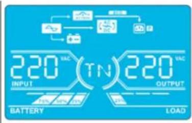
| RN | RN | The first phase |
| SN | SN | The second phase |
| TN | TN | The third phase |
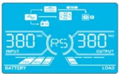
| RS | RS | The first line |
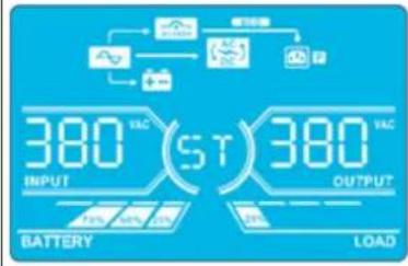
| ST | ST | The second line |
| TR | TR | The third line |
| HS.H | HSH | Hot standby |
| TOL | EOL | Total UPS Number |
| RED | REF | Redundancy Number |
4.7 Setup Menu
Press and hold the Test/Up and Mute/Down buttons simultaneously for longer than one second to enter/exit the Setup Menu.
There are three parameters to set up the UPS. Refer to the illustration below.
Parameter 1 is for program alternatives. Refer to below tables for the programs to set up.
Parameter 2 and Parameter 3 are the setting options or values for each program.
The display will time out after 10 minutes of inactivity. This feature is always enabled.
Note: Use the "Up" or "Down" button to change the programs or parameters.
Parameter 1
Parameter 2 Parameter 3
4. Operation
Programs Available List for Parameter 1:
| Code Description | Bypass / No Output Mode | AC Mode | ECO Mode | CVCF Mode | Battery Mode | Battery Test |
| 01 Output voltage Y* | ||||||
| 02 Output frequency Y | ||||||
| 03 Voltage range for bypass Y | ||||||
| 04 Frequency range for bypass Y | ||||||
| 05 ECO Mode enable/disable Y | ||||||
| 06 Voltage range for ECO Mode Y | ||||||
| 07 Frequency range for ECO Mode Y | ||||||
| 08 Bypass Mode setting Y Y | ||||||
| 09 Maximum battery discharge time setting Y Y Y Y Y Y | ||||||
| 10 Reserved Reserved for future options | ||||||
| 11 Hot standby function setting | Y | |||||
| 12 Neutral loss detection | YYYYYY | |||||
| 13 Battery voltage calibration | YYYYYY | |||||
| 14 Charger voltage adjustment Y Y Y Y Y Y | ||||||
| 15 Inverter A voltage adjustment | Y | YY | ||||
| 16 Inverter B voltage adjustment | Y | YY | ||||
| 17 Inverter C voltage adjustment | Y | YY | ||||
| 18 Output A voltage calibration | Y | YY | ||||
| 19 Output B voltage calibration | Y | YY | ||||
| 20 Output C voltage calibration | Y | YY | ||||
| 21 Charger current setting | Y | |||||
| 22 Charging boards quantity setting | Y | |||||
| 23 Redundancy setting | YYYYYY | |||||
*Y means that this program can be set in this mode.
Note: All parameter settings will be saved only when the UPS shuts down normally with an internal or external battery connection. Normal UPS shutdown means turning off input breaker in Bypass/No Output Mode.
01: Output Voltage
| Interface | Setting |
| BATTERY OUTPUT | Parameter 3: Output voltage For 220/230/240V AC models, you may choose the following output voltage: 220: Output voltage is 220V AC. 230: Output voltage is 230V AC (Default). 240: Output voltage is 240V AC. |
4. Operation
02:Output Frequency
| Interface Setting | |
| 60 Hz, CVCF Mode | |
| 50 Hz, Normal Mode | |
| ATO |
03: Voltage Range for Bypass
| Interface Setting | |
| 176 (03) 264 (03)Battery load | Parameter 2: Set the acceptable low voltage for bypass. For 220/230/240V AC models, setting range is from 176V to 209V and the default value is 176V. Parameter 3: Set the acceptable high voltage for bypass. For 220/230/240V AC models, setting range is from 231V to 276V and the default value is 264V. |
04: Frequency Range for Bypass
| Interface Setting | |
| 468 538Battery LOAD | Parameter 2: Set the acceptable low frequency for bypass. 50 Hz system: Setting range is from 46.0 Hz to 49.0 Hz. 60 Hz system: Setting range is from 56.0 Hz to 59.0 Hz. The default value is 46.0 Hz/56.0 Hz. Parameter 3: Set the acceptable high frequency for bypass. 50 Hz: Setting range is from 51.0 Hz to 54.0 Hz. 60 Hz: Setting range is from 61.0 Hz to 64.0 Hz. The default value is 54.0 Hz/64.0 Hz. |
05:ECO Mode Enable/Disable
| Interface Setting | |
| BATTERY LOAD | Parameter 3: Enable or disable the ECO function. You may choose the following two options: DIS: Disable ECO function (Default). ENA: Enable ECO function. If the ECO function is disabled, the voltage range and frequency range for ECO Mode still can be set, but is void unless the ECO function is enabled. *If the system is running in parallel, be sure to set “DIS” only. |
4. Operation
06: Voltage Range for ECO Mode
| Interface Setting | |
| 209 06 23 15 BATTERY LOAD | Parameter 2: Low voltage point in ECO Mode. The setting range is from -5% to -10% of the nominal voltage. Parameter 3: High voltage point in ECO Mode. The setting range is from +5% to +10% of the nominal voltage. |
07: Frequency Range for ECO Mode
| Interface Setting | |
| 480 520 BATTERY LOAD | Parameter 2: Set the low frequency point for ECO Mode. 50 Hz system: Setting range is from 46.0 Hz to 48.0 Hz. 60 Hz system: Setting range is from 56.0 Hz to 58.0 Hz. The default value is 48.0 Hz/58.0 Hz. Parameter 3: Set high frequency point for ECO Mode. 50 Hz: Setting range is from 52.0 Hz to 54.0 Hz. 60 Hz: Setting range is from 62.0 Hz to 64.0 Hz. The default value is 52.0 Hz/62.0 Hz. |
08: Bypass Mode Setting
| Interface Setting | |
| BATTERY LOAD | Parameter 2: OPN: Bypass allowed. When selected, the UPS will run in Bypass Mode depending on whether the bypass setting is enabled/disabled. FBD: Bypass not allowed. When selected, Bypass Mode is not allowed in any situation. Parameter 3: ENA: Bypass enabled. When selected, Bypass Mode is activated (Default). DIS: Bypass disabled. When selected, automatic bypass is acceptable, but manual bypass is not allowed. Manual bypass means users manually operate UPS for Bypass Mode. For example, pressing OFF button in AC Mode to turn into Bypass Mode. |
09: Maximum Battery Discharge Time Setting
| Interface Setting | |
| 990 BATTERY LOAD | Parameter 3: 000~999: Set the maximum discharge time from 0 to 999 min. The UPS will shut down to the protect battery if the discharge time arrives before the battery is under voltage. The default value is 990 min. DIS: Disable battery discharge protection and backup time will depend on battery capacity. |
10: Reserved
| Interface Setting | |
| SEETO DISBATTERYLOAD | Reserve for future options. |
4. Operation
11: Hot Standby Function Setting
| Interface Setting | |
| HSH YES BATTERY LOAD | Parameter 2:HS.H: Indicates hot standby function. Parameter 3: Enable or disable hot standby function.YES: Hot standby function is enabled. The current UPS is set to host the hot standby function and will restart after AC recovery, even without the battery connected.NO: Hot standby function is disabled. The UPS is running in Normal Mode and cannot restart without battery. |
12: Neutral Loss Detection
| Interface Setting | |
| BATTERY | Parameter 2: N.L: Indicates neutral loss detection function. Parameter 3: DIS: Disable the neutral loss detection function. The UPS will not detect a neutral loss. ATO: The UPS will automatically detect whether or not the neutral is lost. If neutral loss is detected, an alarm will be generated. If the UPS is turned on, it will transfer to Battery Mode. When neutral is restored and detected, the alarm will automatically be muted and the UPS will automatically return to Normal Mode. CHE: The UPS will automatically detect the neutral loss. If neutral loss is detected, an alarm will be generated. If the UPS is turned on, it will transfer to Battery Mode. When neutral is restored, the alarm will NOT be muted automatically and the UPS will NOT return to Normal Mode automatically. Here, you must mute the alarm and make the UPS manually return to Normal Mode. The operation is: First, enter this menu and press the “Enter” key to make the “CHE” flash. Second, press the “Enter” key again to activate the neutral detection (check). If neutral is detected, the alarm will be muted and the UPS will return to Normal Mode. If neutral is not detected, the alarm will continue to go off until the neutral is detected at the next manual checking operation. CHE is the default setting. |
13: Battery Voltage Calibration
| Interface Setting | |
| BATTERY LOAD | Parameter 2: Select "Add" or "Sub" function to adjust battery voltage. Parameter 3: The voltage range is 0V to 9.9V. The default value is 0V. |
14: Charger Voltage Adjustment
| Interface Setting | |
| BATTERY LOAD | Parameter 2: Choose Add or Sub to adjust charger voltage. Parameter 3: The voltage range is 0V to 9.9V. The default value is 0V. Notes: *Before making voltage adjustments, be sure to disconnect all batteries first to get the accurate charger voltage. * Any modification should be suitable to battery specifications. |
4. Operation
15: Inverter-A Voltage Adjustment
| Interface Setting | |
| BATTERY LOAD | Parameter 2: Choose Add or Sub to adjust inverter-A voltage.*Parameter 3: The voltage range is 0V to 9.9V. The default value is 0V.* Add or Sub is according to the output voltage that you set. |
16: Inverter-B Voltage Adjustment
| Interface Setting | |
| BATTERY LOAD | Parameter 2: Choose Add or Sub to adjust inverter-B voltage*. Parameter 3: The voltage range is 0V to 9.9V. The default value is 0V. *It will display number 1 under P456 to represent inverter-B voltage. |
17: Inverter-C Voltage Adjustment
| Interface Setting | |
| BATTERY LOAD | Parameter 2: Choose Add or Sub to adjust inverter-C voltage*. Parameter 3: The voltage range is 0V to 9.9V. The default value is 0V. *It will display number 2 under PachUB to represent inverter-C voltage. |
18: Output-A Voltage Calibration
| Interface Setting | |
| BATTERY | Parameter 2: Always shows OP.V as output voltage. Parameter 3: Shows the internal measurement value of the output-A voltage. You can calibrate it by pressing Up or Down according to the measurement from an external voltage meter. The calibration result will be effective by pressing Enter. The calibration range is limited within +/-9V. This function is normally used for parallel operation. |
19: Output-B Voltage Calibration
| Interface Setting | |
| BATTERY LOAD | Parameter 2: Always shows OP.V as output voltage*. Parameter 3: Shows the internal measurement value of the output-B voltage. You can calibrate it by pressing Up or Down according to the measurement from an external voltage meter. The calibration result will be effective by pressing Enter. The calibration range is limited within +/-9V. This function is normally used for parallel operation. *It will display number 1 under OP.U to represent the output B voltage. |
4. Operation
20: Output-C Voltage Calibration
| Interface Setting | |
| BATTERY OPIU 229 LOAD | Parameter 2: Always shows OP.V as output voltage. Parameter 3: Shows the internal measurement value of the output-C voltage. You can calibrate it by pressing Up or Down according to the measurement from an external voltage meter. The calibration result will be effective by pressing Enter. The calibration range is limited within +/-9V. This function is normally used for parallel operation. *It will display number 2 under OPIU to represent the output C voltage. |
21: Current Charger Setting
| Interface Setting | |
| CHG (2) 0 10. Battery LOAD | Parameter 2: CHG indicates adjust charger current function. Parameter 3: Set the charger current. The setting range is 1A to 4A. The default value is 2A for 30K/40K and 4A for 60K/80K. • 30K-40K: Adjust the charger current function only for one charger board installed on UPS. This feature will not work when more than one charger board is installed. • 60K-80K: Adjust charger current function for only two charger boards installed on UPS. This feature will not work when more than two charger boards are installed. Note: Once the charger board is extended, all installed charger boards will charge the battery at the maximum power of 4A current. Extension board kits are available for the S3M30KX and S3M40KX models (CBKIT30-40) and the S3M60KX and S3M80KX models (CBKIT30-80). |
22:Charging Boards Number Setting
| Interface Setting | |
| CHG (2) 001 BATTERY LGAC | Parameter 2: CHG indicates adjust charging boards quantity function. Parameter 3: Set the charging boards quantity. The setting range is from 1 to 3 and the default value is 1. • 60K-80K: Two charger boards are one group. If the UPS installs four charger boards, it needs to be set to 2. If the UPS installs six charger boards, it needs set to 3. Note: Once the charger board is extended, this parameter has to be changed accordingly. |
23: Redundancy setting
| Interface Setting | |
| Parameter 2: TOL it indicates the quantity of UPS. The setting range is from 1 to 3 and the default value is 1. Parameter 3: RED it indicates the quantity of redundant UPS. The setting range is from 0 to 2 and the default value is 0. Note: The setting quantity of each UPS needs to equal the quantity of the UPS connected in parallel for redundancy. If setting quantity is not equal to the quantity of UPS in the system, the UPS will generate a warning. | |
4. Operation
4.8 Operating Mode/Status Description
The following table shows the LCD screen for operating modes and status.
(1) If the UPS is in normal operation, it will show seven screens one-by-one, which represents 3-phase input voltages (An, bn, Cn), 3-line input voltages (Ab, bC, CA) and frequency in turns.
(2) If parallel UPS systems are successfully set up, it will show one more screen with "PAR" in Parameter 2 and assigned number in Parameter 3 (as shown in the below parallel screen illustration). The primary UPS will be assigned automatically as "001". Secondary UPS systems will be assigned as either "002" or "003". The assigned numbers may be changed dynamically in the operation.
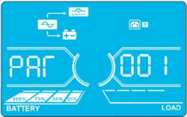
Parallel Screen
| Operating Mode/Status | ||
| UPS Power On | Description | When the UPS is powered on, it will enter into this mode for a few seconds as the CPU and system initialise. |
| LCD Panel | ||
| No-output Mode | Description When bypass voltage/frequency is out of acceptable range or bypass is disabled (or forbidden), the UPS will enter No-output Mode if powering on or turning off the UPS. This means the UPS has no output. The alarm will beep every two minutes. | |
| LCD Panel | ||
4. Operation
| No-output Mode(continued) | 338(VC)(ST)000VCCBATTERY LOAD | 338(VC)(TR)000VCCBATTERY LOAD | |
| 500(VC)(SN)000VCCBATTERY LOAD | 500(VC)(SN)000VCCBATTERY LOAD | ||
| AC Mode Description When input voltage is within acceptable range, the UPS will provide pure and stable AC power to output. The UPS will also charge the battery at AC Mode. | |||
| LCD Panel | 220(VC)(RN)220(VC)BATTERY LOAD | 220(VC)(SN)220(VC)BATTERY LOAD | 220(VC)(SN)220(VC)BATTERY LOAD |
| 220(VC)(TN)220(VC)BATTERY LOAD | 220(VC)(PS)220(VC)BATTERY LOAD | 220(VC)(PS)220(VC)BATTERY LOAD | |
| 380(VC)(ST)380(VC)BATTERY LOAD | 380(VC)(TR)380(VC)BATTERY LOAD | 380(VC)(TR)380(VC)BATTERY LOAD | |
| 500(VC)(SN)500(VC)BATTERY LOAD | 500(VC)(SN)500(VC)BATTERY LOAD | 500(VC)(SN)500(VC)BATTERY LOAD | |
| ECO Mode | Description | When the input voltage is within voltage regulation range and ECO Mode is enabled, UPS will bypass voltage to output for energy saving. | |
| LCD Panel | 220(VC)(RN)220(VC)BATTERY LOAD | 220(VC)(SN)220(VC)BATTERY LOAD | |
4. Operation
ECO Mode (continued)
CVCF Mode Description When the
output frequency is set to "CF", the inverter will output constant frequency (50 Hz or 60 Hz). In this mode, the UPS will have no bypass output but still charge the battery.
LCD Panel
4. Operation
| Battery Mode | Description | When the input voltage/frequency is beyond the acceptable range or experiences a power failure, the UPS will provide backup power from the battery. The alarm will beep every 4 seconds. | |
| LCD Panel | 260VAC(RN)220VAC BATTERY LOAD | 260VAC(SN)220VAC BATTERY LOAD | |
| 260VAC(TN)220VAC BATTERY LOAD | 260VAC(RS)380VAC BATTERY LOAD | ||
| 260VAC(ST)380VAC BATTERY LOAD | 260VAC(TR)380VAC BATTERY LOAD | ||
| 260VAC(30)500u BATTERY LOAD | 260VAC(TR)380VAC BATTERY LOAD | ||
| Bypass Mode | Description | When input voltage is within acceptable range and bypass is enabled, turn off the UPS and it will enter Bypass Mode. The alarm will beep every two minutes. | |
| LCD Panel | 220VAC(RN)220VAC BATTERY LOAD | 220VAC(SN)220VAC BATTERY LOAD | |
| 220VAC(TN)220VAC BATTERY LOAD | 220VAC(RS)380VAC BATTERY LOAD | ||
| 220VAC(ST)380VAC BATTERY LOAD | 220VAC(TR)380VAC BATTERY LOAD | ||
4. Operation
| Bypass Mode(continued) | 500 INPUT OUTPUT BATTERY LOAD | ||
| Battery Test | Description | When the UPS is in AC Mode or CVCF Mode, press the "Test" button for more than 0.5 seconds. TheUPS will beep once. The line between I/P and inverter icons will blink to remind users this operation is used to check the battery status. | |
| LCD Panel | 229VCC(RN)220VCC BATTERY LOAD | ||
| 229VCC(TN)220VCC BATTERY LOAD | |||
| 229VCC(ST)380VCC BATTERY LOAD | |||
| 229VCC(05)500VCC BATTERY LOAD | |||
| Warning Status | Description | If some errors occur in the UPS (but it is still operating normally), it will show one more screen to represent the warning situation. In the warning screen, the △on will be flashing. It can show up to 3 error codes, with each code indicating one error. The code meaning can be found in the warning code table in section 4.11. | |
| LCD Panel | 09 INPUT OUTPUT BATTERY LOAD | ||
4. Operation
| Fault Status | Description | When a UPS fault occurs, the inverter will be blocked. The fault code will display on the screen, and the ∅on will light up solid (it will not flash). The code meaning can be found in the fault code table in section 4.9. |
| LCD Panel | INPUT OUTPUTBATTERY LOAD |
4.9 Fault Codes - When A con is Solid (Not Flashing)
| Fault code | Fault Event Icon | Fault Code Fault Event Icon | |||
| 01 | Bus start failure | None 42 DSP communication failure | None | ||
| 02 | Bus over | None 43 Overload | |||
| 03 | Bus under | None 46 Incorrect UPS setting | None | ||
| 04 | Bus unbalance | None 47 MCU communication failure | None | ||
| 06 | Converter | over current | None 48 | Two DSP firmware versions are incompatible in parallel system | |
| 11 | Inverter soft start failure | None 60 Bypass phase short circuited | |||
| 12 | High inverter voltage | None 61 Bypass SCR short circuited | None | ||
| 14 | Inverter R output (line to neutral) short circuited | 62 Bypass SCR open circuited | None | ||
| 15 | Inverter S output (line to neutral) short circuited | 63 Voltage waveform abnormal in R phase | None | ||
| 16 | Inverter T output (line to neutral) short circuited | 64 Voltage waveform abnormal in S phase | None | ||
| 17 | Inverter R-S output (line to line) short circuited | 65 Voltage waveform abnormal in T phase | None | ||
| 18 | Inverter S-T output (line to line) short circuited | 66 Inverter current sample abnormal | None | ||
| 19 | Inverter T-R output (line to line) short circuited | 67 Bypass O/P short circuited | |||
| 1A | Inverter A negative power fault | None | 68 | Bypass O/P line to line short circuited | |
| 1B | Inverter B negative power fault | None | 69 | Inverter SCR short circuited | None |
| 1C | Inverter C negative power fault | None | 6C | BUS voltage drops too fast | None |
| 21 | Battery SCR short circuited | None | 6D | Current sampling error value | None |
| 23 | Inverter relay open circuited | None | 6E | SPS power error | None |
| 24 | Inverter relay short circuited | None | 6F | Battery polarity reverse | None |
| 25 | Line wiring fault | None | 71 | PFC IGBT over-current in R phase | None |
| 31 | Parallel communication failure | None | 72 | PFC IGBT over-current in S phase | None |
| 32 | Host signal failure | None | 73 | PFC IGBT over-current in T phase | None |
| 33 | Synchronous signal failure | None | 74 | INV IGBT over-current in R phase | None |
| 34 | Synchronous trigger signal failure | None | 75 | INV IGBT over-current in S phase | None |
| 35 | Parallel communication loss | None | 76 | INV IGBT over-current in T phase | None |
| 36 | Parallel output current unbalance | None | |||
| 41 | Over temperature | None | |||
4. Operation
4.10 Warning Indicator- When A's Flashing
| Warning Icon (flashing) Alarm | ||
| Battery low | LEDS | Beeping every second |
| Overload | OVERLOAD | Beeping twice every second |
| Battery unconnected | BATTFAUL | Beeping every second |
| Over charge | 100% 75% 50% 25% BATTERY | Beeping every second |
| EPO enable | P | Beeping every second |
| Fan failure/Over temperature | AC DC | Beeping every second |
| Charger failure | + - | Beeping every second |
| I/P fuse broken | ~ | Beeping every second |
| Other warnings (refer to section 4-11) | WEEDED | Beeping every second |
4.11 Warning Codes - When A con Is Flashing
If errors occur in the UPS but it continues to run normally, the LCD screen will show a warning. In the warning screen, the icon will flash. Up to three error codes may display, with each code indicating one error.
| Warning Code Warning Event | Warning Code Warning Event | ||
| 01 Battery disconnected 22 Bypass situations are different in parallel | system | ||
| 02 IP Neutral loss 33 Locked in bypass after overload 3 times in 30 | minutes | ||
| 04 IP phase abnormal 34 Converter current unbalanced | |||
| 05 Bypass phase abnormal 3A Cover of maintenance switch is open | |||
| 07 Over charge 3C Utility power extremely unstable | |||
| 08 Low battery 3D Bypass is unstable | |||
| 09 Overload | 3E Battery voltage too high | ||
| 0A | Fan failure | 3F Battery voltage unbalanced | |
| 0B EPO enable | 40 Charge short circuited | ||
| 0D Over temperature | 44 Redundancy setting fail | ||
| OE | Charger failure | 24 Parallel output load different | |
| 21 Line situations are different in parallel system | 35 Battery Fuse open | ||
5. Communication
5.1 Smart Monitoring Slot: SNMP Monitoring using the WEBCARDLX card or Contact Closure Mangement using RELAYCARDSV (Optional cards)
Install an optional WEBCARDLX card in this slot to remotely monitor and control the UPS via a network. The RELAYCARDSV may also be inserted in this slot to provide dry contact communication functionality. Refer to the WEBCARDLX and RELAYCARDSV manuals at tripplite.com for further details.
Note: Only one card may be used at a time.
5.2 EPO Connector
The EPO is included as standard for site safety. Its default setting is Normally Closed (N.C.), with pins 1 and 2 closed for normal UPS operation. To enable EPO function, open contacts with pins 1 and 2.
5.3 RS-232 Port
The RS-232 port is built into the UPS system's rear panel (S3M30KX and S3M40KX models) or behind the front door (S3M60KX and S3M80KX models) to provide service support when upgrading the UPS system software.
5.4 USB Port
This port is for service purposes only.
30kVA and 40kVA Models
60kVA and 80kVA Models
6. Troubleshooting
If the UPS system does not operate correctly, identify the problem using the table below.
| Symptom Possible Cause Remedy | ||
| No indication and alarm in the front display panel even though the mains is normal. | The AC input power is not connected correctly or securely. | Check to make sure input cable is firmly connected to the mains. |
| The icon and the warning code flash on LCD display. The alarm beeps every second. | EPO function is activated. At this time, the EPO switch is set to "OFF" or the jumper is open. | Set the circuit in closed position to disable the EPO function. |
| The icon and flash on the LCD display. The alarm beeps every second. | The external or internal battery is incorrectly connected. | Check to make sure all batteries are securely and correctly connected. |
| The icon and flash on the LCD display. The alarm beeps twice every second. | UPS is overloaded. Remove excess loads from UPS output. | |
| UPS is overloaded. Devices connected to the UPS are fed directly by the electrical network via the Bypass. | Remove excess loads from UPS output. | |
| After repetitive overloads, the UPS is locked in Bypass Mode. Connected devices are fed directly by the mains. | Remove excess loads from UPS output, then shut down the UPS and restart. | |
| Fault code is shown as 43. The icon displays on the LCD. The alarm beeps continuously. | UPS is overloaded for too long and becomes fault. The UPS automatically shuts down. | Remove excess loads from the UPS output and restart. |
| Fault code is shown as 14, 15, 16, 17, 18 or 19, the icon displays on the LCD. The alarm beeps continuously. | The UPS automatically shuts down due to a short circuit on the UPS output. | Check output wiring and if connected devices are in short circuit status. |
| Other fault codes are shown on the LCD. The alarm beeps continuously. | A UPS internal fault has occurred. Contact your dealer. | |
| Battery backup time is shorter than the nominal value. | Batteries are not fully charged. Charge the batteries for at least 7 hours, then check capacity. If the problem still persists, consult your dealer. | |
| Batteries are defective. Contact your dealer to replace the battery. | ||
| The icon and flash on the LCD. The alarm beeps every second. | Fan is locked or not working, or the UPS temperature is too high. | Check fans and notify dealer. |
| The warning code 02 and the icon flash on the LCD. The alarm beeps every second. | The input neutral wire is disconnected. Check and correct the input neutral connection. If the connection is ok and the warning still displays, refer to section 4.7. To enter the neutral loss check menu, first check that parameter 3 is "CHE". If it is, press the "Enter" key to make "CHE" flash, then press "Enter" again to clear the alarm. If the warning still exists, check input fuses of L2 and L3. | |
| The L2 or L3 input fuse is broken. Replace the fuse. | ||
| The warning code 44 and the icon flash on the LCD. The alarm beeps every second. | The Redundancy setting is in error. Check Redundancy setting. The setting quantity needs to be set equal to the quantity of UPS systems. The UPS setting quantity needs to be set greater than the setting quantity of redundant UPS systems. | |
7. Storage and Maintenance
7.1 Storage
The UPS system must be stored in a clean, secure environment with a temperature less than 40°C and a relative humidity less than 90% (non-condensing). Store the UPS system in its original shipping container, if possible. If installation occurs more than 6 months after you receive the UPS system, recharge the batteries for at least 24 hours prior to use. Do not rely on the UPS system to provide backup power to connected equipment until the batteries are fully charged.
Note: If the UPS system remains off for an extended period of time, it should be turned on periodically to allow the batteries to recharge. The UPS system should be turned on and the batteries should be recharged at least one uninterrupted 24-hour period every 3 months. Failure to recharge the batteries periodically may cause irreversible battery damage.
7.2 Maintenance
- The UPS system operates with hazardous voltages. Repairs should only be performed by qualified maintenance personnel.
- Even after the unit is disconnected from the mains, potentially dangerous components inside the UPS system are still connected to the battery packs.
- Before carrying out any kind of service and/or maintenance, disconnect the batteries and verify no current is present and no hazardous voltage exists in the terminals of high-capability capacitors, such as BUS-capacitors.
- Only qualified technicians taking the required precautionary measures may replace batteries and supervise operations. Unauthorised persons should not perform battery maintenance.
- Verify no voltage between the battery terminals and the ground is present before maintenance or repair. The battery circuit is not isolated from the input voltage. Hazardous voltages may occur between the battery terminals and the ground.
- Batteries may cause electric shock and have a high short-circuit current. Remove all wristwatches, rings and other metal personal objects before maintenance or repair, and only use tools with insulated grips and handles for maintenance or repair.
- When replacing the batteries, install the same number, type and battery capacity.
- Do not attempt to dispose of batteries by burning them. This could cause a battery explosion. Batteries must be appropriately deposed of according to local regulations.
- Do not open or destroy batteries. Escaping electrolytes may be toxic and can cause injury to the skin and eyes.
- To avoid fire hazards, replace the fuse only with the same type and amperage.
- Do not disassemble the UPS system.
7.3 Battery
Tripp Lite's S3MX-Series UPS systems use sealed lead-acid batteries. The battery life depends on operating temperature, the usage, and the charging/discharging frequency. High temperature environments and high charging/discharging frequency will quickly shorten the battery life. Please follow the suggestions below to ensure a normal battery lifetime.
- Keep operating temperature between 0°C 40°C .
- For optimum battery performance and life, operate at a regulated 25°C
- When the UPS needs to be stored for an extended period of time, the batteries must be recharged once every three months and the charging time must be at least 24 hours each time.
7.4 Fan
Higher temperatures shorten fan life. When the UPS is running, make sure all fans are working normally and make sure air can move freely around and through the UPS. If not, replace the fans.
Note: Contact Tripp Lite Technical Support for more maintenance information. Do not perform maintenance if you are not qualified to do so.
8. Specifications
| MODELS S3M30KX/KXD* S3M40KX/KXD* S3M60KX/KXD* S3M80KX/KXD* | ||||
| Capacity (VA) 30 kVA 40 kVA 60 kVA 80 kVA | ||||
| Capacity (Watts) 27 kW 36 kW 54 kW 72 kW | ||||
| INPUT | ||||
| Nominal Voltage Ph-Ph 380V/400V/415V (Ph-N 220V/230V/240V) | ||||
| Voltage Range | Ph-Ph 208-478V at < 50% Load; Ph-Ph 208-478V to 305-478V at 50% to 80% Load(Voltage Range Varies with Load); Ph-Ph 305-478V at > 80% Load | |||
| Voltage Comeback Low-Loss Voltage +10V; High-Loss Voltage -10V | ||||
| Nominal Frequency 50/60 Hz (Auto-Selectable) | ||||
| Frequency Range 46-54 Hz (50 Hz System); 56-64 Hz (60 Hz System) | ||||
| Phase 3-Phase with Neutral (3-Phase, Neutral + Ground) | ||||
| Power Factor (100% Load) ≥ 0,99 | ||||
| Harmonic Distortion (THDi; 100% Load) < 3% | ||||
| OUTPUT | ||||
| Phase 3-Phase with Neutral (3-Phase, Neutral** + Ground) | ||||
| Nominal Voltage Ph-Ph 380V/400V/415V (Ph-N 220V/230V/240V) | ||||
| AC Voltage Regulation(Double-Conversion Mode) | ±1% (Balanced Load) | |||
| AC Voltage Regulation(Converter Mode or Battery Mode) | ±1% | |||
| Power Factor 0,9 | ||||
| AC Voltage Regulation (ECO Mode) | ± 11V of Nominal | |||
| Frequency | 46-54 Hz (50 Hz System); 56-64 Hz (60 Hz System) | |||
| Frequency Regulation(Converter Mode or Battery Mode) | ± 0,1 Hz | |||
| Frequency Range (Battery Mode) | 50 Hz ± 0,1 Hz or 60 Hz ± 0,1 Hz | |||
| Overload (AC Mode) | Up to 110% = 10 min; Up to 130% = 1 min; > 130% = 1 s | |||
| Overload (Battery Mode) | Up to 110% = 30 s; Up to 130% = 10 s; > 130% = 1 s | |||
| Current Crest Ratio | 3:1 Maximum | |||
| Harmonic Distortion (100% Load) | ≤ 2% THD (Linear Load); ≤ 4% THD (Non-Linear Load) | |||
| Transfer Time (Line ←→ Battery) | 0 ms | |||
| Transfer Time (Inverter ←→ Bypass) | Synchronous = 0 ms; Asynchronous < 4 ms | |||
| Transfer Time (Inverter ←→ ECO) | < 10 ms | |||
| BYPASS INPUT | ||||
| Nominal Voltage | Ph-Ph 380V/400V/415V | |||
| Phase 3-Phase with Neutral (3-Phase, Neutral + Ground) | ||||
| Voltage Range | Upper Limit: Ph-N 231-264VLower Limit: Ph-N 176-209V | |||
| Nominal Frequency 50/60 Hz (Auto-Selectable) | ||||
| Frequency Range | Selectable: ± 1-4 Hz (Default: ± 4 Hz) | |||
| Overload (Bypass Mode) | < 150% = 1 min | |||
| EFFICIENCY | ||||
| AC Line Mode | 94% at 100% Resistive Load; 93,5% at 50% Resistive Load | |||
| ECO Mode | 98%, at 100% Resistive Load; 97,5% at 50% Resistive Load | |||
| Battery Mode | 93,5% at 100% Resistive Load; 93% at 50% Resistive Load | |||
| PARALLEL | ||||
| Parallel for Capacity and Redundancy Up to 3 Units | ||||
| INTERNAL BATTERIES (S3M30KX/KXD* and S3M40KX/KXD* include internal batteries. Versions are also available withoutinternal batteries installed: S3M30KX-NIB/NXD-NIB*.) | ||||
| Type | 12V Non-Spillable VRLA AGM/GEL | No Internal Batteries | ||
| Capacity | 9 Ah | 10 Ah | ||
| Quantity | 80 (2 x Strings of 20 + 20) | External Batteries Required forS3M30KX-NIB/KXD-NIB,S3M40KX-NIB/KXD-NIB,S3M60KX/KXD, S3M80KX/KXD,S3M100KX/KXD, S3M120KX/KXD,S3M160KX/KXD and S3M200KX/KXD | ||
| Runtime (50% / 100% Load) | 17/5.7 min | 15/5 min | ||
| Recharge Time | 9 h to 90% | |||
| Maximum Charging Current | 2A ± 10% | |||
| Float Voltage | 13,65V/Battery; 2,27V/Cell | |||
| Boost Charging | 14,1V/Battery; 2,35V/Cell | |||
| End of Discharge | 10V/Battery; 1,67V/Cell | |||
- "KXD" and "KXD-NIB" models are dual-AC input capable. **The UPS output Neutral must be connected to the Load Neutral at all times.
8. Specifications
| MODELS S3M30KX/KXD* S3M40KX/KXD* S3M60KX/KXD* S3M80KX/KXD* | ||||
| EXTERNAL BATTERIES (S3M60KX/KXD*, S3M80KX/KXD* require external batteries for backup. S3M30KX-NIB/KXD-NIB*, S3M40KX-NIB/KXD-NIB* [without internal batteries installed], require external batteries for backup). | ||||
| Type 12V Non-Spillable VRLA AGM/GEL | ||||
| DC Nominal Acceptance Voltage ± 240 VDC | ||||
| Quantity 40N (N ≥ 1 x Strings of 20 + 20) | ||||
| Maximum Charging Current | Adjustable up to 4A ± 10% (Max 12A with 2 x CBKIT30-40.) | Adjustable up to 8A ± 10% (Max 24A with 2 x CBKIT30-80.) | ||
| Float Voltage 13,65V/Battery; 2,27V/Cell | ||||
| Boost Charging 14,1V/Battery; 2,35V/Cell | ||||
| End of Discharge 10V/Battery; 1,67V/Cell | ||||
| Charger Temperature Compensation N/A | ||||
| PHYSICAL | ||||
| Dimensions (H x W x D) 1000 x 300 x 815 mm 1010 x 360 x 790 mm | ||||
| Unit Weight (With Internal Batteries) 265 kg 316 kg | N/A | N/A | ||
| Unit Weight (Without Internal Batteries) 60 kg | 61 kg 108 kg | 113 kg | ||
| ENVIRONMENT | ||||
| Operating Temperature | 0 to 40°C (≤ 25°C for optimal battery lifespan.) | |||
| Storage Temperature | 0 to 35°C (UPS with Batteries), -15 to 60°C (UPS without Batteries) | |||
| Operating Humidity | 0 to 95% (Non-Condensing) | |||
| Operating Altitude | < 1000 m (Derate output power by 1% per 100 m above 1000 m.) | |||
| Audible Noise | < 60 dBA at 1 m | < 70 dBA at 1 m | < 75 dBA at 1 m | |
| Heat Dissipation (100% Load) | 5527 BTU/h | 7362 BTU/h | 11054 BTU/h | 14738 BTU/h |
| Heat Dissipation (50% Load) | 2994 BTU/h | 3992 BTU/h | 5998 BTU/h | 7984 BTU/h |
| MANAGEMENT | ||||
| Network Management Interface | Requires optional WEBCARDLX. (Monitor, control and reboot the UPS using HTML5 web, SSH/telnet and SNMP interfaces. Supports centralised management through integration with a wide range of Network Management Systems and DCIM platforms.) | |||
| Control Panel | 62 mm LCD with supplemental LEDs. | |||
| Contact Closure Interface | Requires Optional RELAYCARDSV Programmable Relay I/O Card | |||
| Remote Emergency Power Off (REPO) | Feature Included (Default: Normally Closed) | |||
| RS-232 | Included (Service Only) | |||
| STANDARDS | ||||
| Safety | IEC 62040-1:2008+A1:2013 (TUV Approval) | |||
| EMC/EMI | EN 62040-2:2006 (Category C3) (TUV Approval) | |||
| Ingress Protection Rating | IP20 | |||
| CE Marking | Yes | |||
| RoHS Compliant | Yes | |||
| Quality Management System | ISO 9001 | |||
| OTHER INFORMATION | ||||
| Colour | RAL 9005 Jet Black | |||
| Mobility | Casters | |||
| ACCESSORIES (Sold Separately) | ||||
| Scalable Battery Cabinets | Available models include BP480V100-NIB, BP480V100, BP480V65-NIB, BP480V65, BP480V40-NIB, BP480V40, BP480V10-NIB, BP480V10, BP480V09. (NIB=No internal batteries.) | |||
| Network Management Card | WEBCARDLX (Monitor, control and reboot the UPS using HTML5 web, SSH/telnet and SNMP interfaces. Supports centralised management through integration with a wide range of Network Management Systems and DCIM platforms.) | |||
| Battery Temperature Compensation Thermostat Kit | MODBUSCARDSV (Modbus protocol via RS-485 interface.) | |||
| Remote Environmental Sensors (Require WEBCARDLX.) | E2MT (Temperature Sensor); E2MTDO (Temperature Sensor with Digital Outputs); E2MTDI (Temperature Sensor with Digital Inputs); E2MTHDI (Temperature/Humidity Sensor with Digital Inputs) | |||
| Contact Closure Card | RELAYCARDSV | |||
| External Bypass Panel | Contact your local sales representative or distributor for more information. | |||
| Scalable Charger Board Kits | CBKIT30-40 (Adds 4A; Max 2) | CBKIT30-80 (Adds 8A; Max 2) | ||
- "KXD" and "KXD-NIB" models are dual-AC input capable.
8. Specifications
Battery Cabinet Dimensions
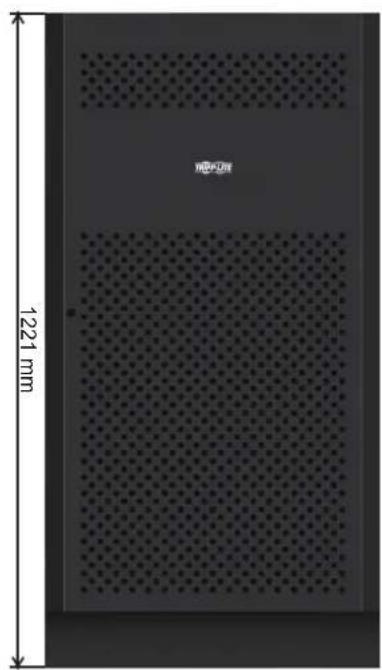
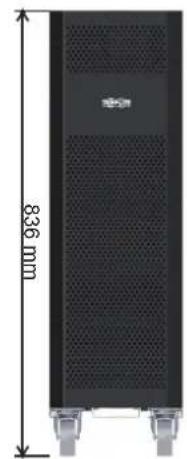
12V 9/10Ah x 80pcs12V 40Ah x 40pcs1
| Battery Cabinet Models | breaker Included | Dimensions (H x W x D) mm Description | |
| BP480V100 | 400A, 3-Pole | 1501 x 826 x 1136 | Battery Cabinet with 40 x 100Ah batteries |
| BP480V100-NIB | Battery Cabinet without batteries, but designed for 40 x 100Ah batteries (includes battery cabling and breaker) | ||
| BP480V65 | 300A, 3-Pole | Battery Cabinet with 40 x 65Ah batteries | |
| BP480V65-NIB | Battery Cabinet without batteries, but designed for 40 x 65Ah batteries (includes battery cabling and breaker) | ||
| BP480V40 | 200A, 3-Pole 1220 x 626 x 900 | 626 x 900 | Battery Cabinet with 40 x 40Ah batteries |
| BP480V40-NIB | Battery Cabinet without batteries, but designed for 40 x 40Ah batteries (includes battery cabling and breaker) | ||
| BP480V10 | with 80 x 9Ah batteries Fuse, 100 Amps 836 x 250 x 779 | 836 x 250 x 779 | Battery Cabinet with 80 x 10Ah batteries |
| BP480V09 Battery Cabinet | |||
| BP480V10-NIB | Battery Cabinet without batteries, but designed for 80 x 10Ah/9Ah batteries (includes battery cabling and fuse) | ||
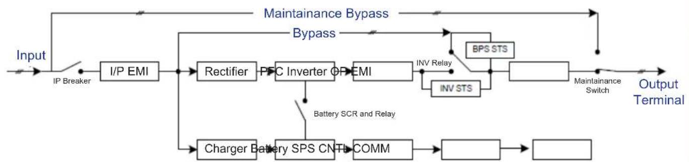
UPS Functional Block Diagram
9. Warranty
Your SmartOnline 3-Phase UPS System is covered by the limited warranty described below. Extended warranty (3- and 4-year) and start-up service programs are available. For more information, call Tripp Lite Customer Service at +1.773.869.1234 or visit triplite.com/support.
3-Phase UPS System Limited Warranty
Seller warrants this product, if used in accordance with all applicable instructions as verified by Tripp Lite's "Start-up" service, to be free from original defects in material and workmanship for a period of two (2) years from the date of start-up. If the product should prove defective in material or workmanship within that period, Seller will repair or replace the defective parts without charge for labor or parts. If the product was not started up by authorised Tripp Lite service, replacement parts will be provided but labor charges will apply based on published Tripp Lite Time and Material Rates. Tripp Lite will assign to you any warranties provided by the manufacturers of components of the Tripp Lite product. Tripp Lite makes no representations as to the extent of these warranties and assumes no responsibility for warranties of these components. Service under this Warranty can only be obtained by contacting: Tripp Lite Customer Service; 1111 W. 35th Street; Chicago IL 60609; +1.773.869.1234; intlservice@tripplite.com.
THIS WARRANTY DOES NOT APPLY TO NORMAL WEAR OR TO DAMAGE RESULTING FROM ACCIDENT, IMPROPER INSTALLATION, MISUSE, ABUSE OR NEGLECT. SELLER MAKES NO EXPRESS WARRANTY OTHER THAN THE WARRANTY EXPRESSLY SET FORTH HEREIN. EXCEPT TO THE EXTENT PROHIBITED BY APPLICABLE LAW, ALL IMPLIED WARRANTYES, INCLUDING ALL WARRANTYES OF MERCHANTABILITY OR FITNESS, ARE LIMITED IN DURATION TO THE WARRANTY PERIOD SET FORTH ABOVE; AND THIS WARRANTY EXPRESSLY EXCUSES ALL INCIDENTAL AND CONSEQUENTIAL DAMAGES. (Some states do not allow limitations on how long an implied warranty lasts, and some states do not allow the exclusion or limitation of incidental or consequential damages, so the above limitations or exclusions may not apply to you. This Warranty gives you specific legal rights, and you may have other rights which vary from jurisdiction to jurisdiction).
Regulatory Compliance Identification Numbers
For the purpose of regulatory compliance certifications and identification, your Tripp Lite product has been assigned a unique series number. The series number can be found on the product nameplate label, along with all required approval markings and information. When requesting compliance information for this product, always refer to the series number. The series number should not be confused with the marketing name or model number of the product.
WEEE Compliance Information for Tripp Lite Customers and Recyclers (European Union)

Under the Waste Electrical and Electronic Equipment (WEEE) Directive and implementing regulations, when customers buy new electrical and electronic equipment from Tripp Lite they are entitled to:
- Send old equipment for recycling on a one-for-one, like-for-like basis (this varies depending on the country)
- Send the new equipment back for recycling when this ultimately becomes waste
Tripp Lite has a policy of continuous improvement. Specifications are subject to change without notice. Photos and illustrations may differ slightly from actual products.


1111 W. 35th Street, Chicago, IL 60609 USA · triplite.com/support
Modelos: S3M30KX, S3M30KXD, S3M30KX-NIB, S3M30KXD-NIB, S3M40KX, S3M40KXD, S3M40KX-NIB, S3M40KXD-NIB, S3M60KX, S3M60KXD, S3M80KX, S3M80KXD
Entrada: 220V / 230V / 240V (Fase - Neutro) 380V / 400V / 415V (Fase - Fase), 30 4 Hilos + Tierra Física
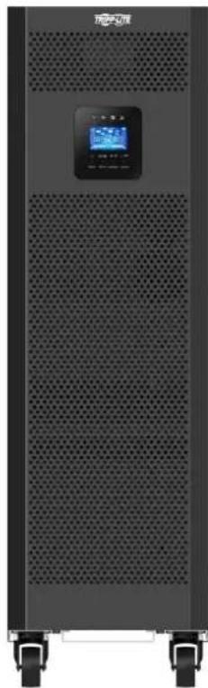
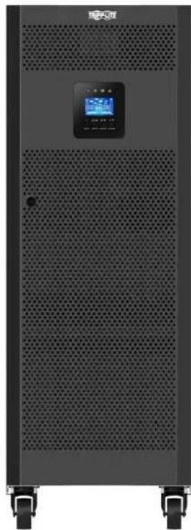


1111 W. 35th Street, Chicago, IL 60609 EE. UU. triplite.com/support
Articulos necessities:
Modèles : S3M30KX, S3M30KXD, S3M30KX-NIB, S3M30KXD-NIB, S3M40KX, S3M40KXD, S3M40KX-NIB, S3M40KXD-NIB, S3M60KX, S3M60KXD, S3M80KX, S3M80KXD
Entree : 220/230/240 V (Ph-N), 380/400/415 V (Ph-Ph), 3Ø 4 fils + masse
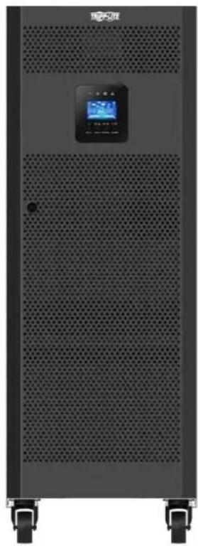


1111 W. 35th Street, Chicago, IL 60609 USA · tripplite.com/support
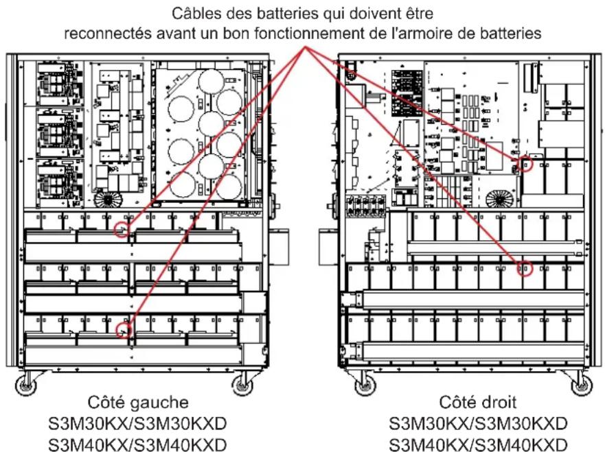
Figure 3.3 Figure 3.4
1111 W. 35th Street, Chicago, IL 60609 USA · triplite.com/support
PykoBODCTBO N0lb30BaTeJia
Mодени: S3M30KX, S3M30KXD, S3M30KX-NIB, S3M30KXD-NIB, S3M40KX, S3M40KXD, S3M40KX-NIB, S3M40KXD-NIB, S3M60KX, S3M60KXD, S3M80KX, S3M80KXD
BxOJHoe nHTaHHe: 220/230/240 B (Φ.-H.), 380/400/415 B (Φ.-Φ.), 3-Φa3Hoe, 4 npoBoda + 33
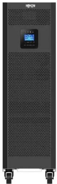
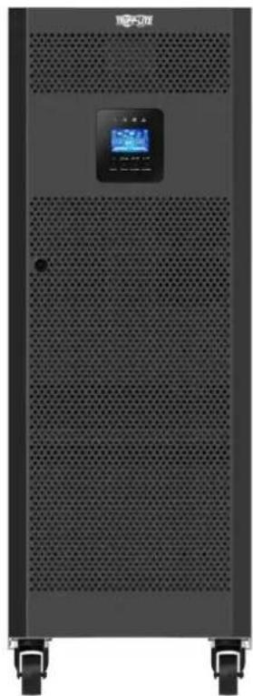
EAC


1111 W. 35th Street, Chicago, IL 60609 USA - tripplite.com/support Oxpaharetca abtopckim npabom © 2019 Tripp Lite. Ipepeeta kzaanpeetaetc.
CopepxaHne
1. BBeDHeNe 165
2. Baxhble npedynpeKdHn no TeXnke 6e3onachoctn 166
2.1 PpdeynpejxdenHnOTHoCHTenbHo MeCaTa pa3MeueHHN 16P 166
2.2IpeynppeKdEHHoOTHOHIOPOKnIOeHHoObopydoBaHHa 166
2.3 Ppeynpeckdenea OHoCtebHo 6aTaapei 166
2.4 TpaHcnopTnpBbKa HxpaHeHne 167
2.5 IoproToBka 167
2.6 YctaHOBka 167
2.7 PpeynpexdEHHO tHOIOKIOHn 167
2.8 3Kcnnyataa 168
2.9 CoTBeTCTBmE CTAnDapTam 168
3. YctaHOBKa n HacTpoiKa 169
3.1 PaCnakOBka NOCMOTp 169
3.2 IopraoknoKIOKJIueHnBHyTpeHHnx6aTaepmmoS3M30KX/KXD m S3M40KX/KXD
3.3 YctaHOBKa BHyTpEHHX 6aTapeB MoDEnax S3M30KX-NIB/KXD-NIB u S3M40KX-NIB/KXD-NIB 172
3.4 UcTaHOBKa OdMHOuHOrO IVbI 184
3.5 YcTaHOBKa IB B CHTeMaX c npaJIenBbHbIM noJKnIOUeHHem 186
3.6 PoiKIIouHHe BHeuHn 6aTaPei 187
3.7y CTaHOBKa CO CDbOeHbIM BxOdom NITaHnI NpeMeHHOro ToKa 188
5. CpeCTBa B3aImoJeCTBn 210
5.1 Pa3beM dIy IIOKJIIOUeHnIg SNMP-KapTbI 210
5.2 Pa3beM EPO 210
5.3 IopT RS-232 210
5.4 Iopr USB 210
6. BbIaBHeHne uYcTaPaeHne HncnPaBHoCTe 211
7. XpahenHe n TexHnueckoe o6cIyXmbaHne 212
7.1 XpaheHne
212
7.2TexHueckoeobcnykBaHne 212
7.3 BaTapeR
212
7.4 BeHTWIJATOP
212
8. Texhueckne xapaKtepncn 213
9. TapaHTnHbIe 06a3aTeJbCTBa 216
English 1
Espanol 55
Français 109
Deutsch 217
1.В蜱てнe
Bbmyckaembl kcmnnaHm Tripp Lite nctouhik bcnepebohoro nntaHn (N5) cepnn SmartOnl S3MKX npdctabniet coboh hesacmbn ot HapnKHeH uactotb trpexpa3hbn OH-ain H5P CBOHbIM pno6ba0BaHEM. 3OT N5H enpepbmbHO CTabm3pyet BxOHDoe 3eKTPueckoe nHTAHme, yCTpaHra TEM cambIM hapyehnpekma nHTAHn, KOtOpBie B npotmbHom cnyae npbOdnHb6bl K BbIXOyI 3C TPOA YBCBTBnBbIX 3eKTPoHHbIX yCTPOCB, IN CBODA K MHNMYDINTEBHOCTb IpocToEB, BB3bBAeMbX KOlebaHMM MOUHOCTn IN nepe6oMM B heprochabKeHH.
MoJIeN I6I cepn S3MKX cKHOCTpyuPoBaHb B COOTBETCBN C BbOcayuHMM CTaHdaptAM KauCtBA N npO3BOJNTeNbHOCTN IOECENeuMbAOT CneJyUHmEOB3MOxHOCTN:
Dpyrne npednaraemble onu nn KOMnEeTyouune
DOnonHtneBna 3apnHa nIaTn yBeNueHHe emKoCTn 3apnHoro yCtpnoCTBa:
3apnblhe nlahtbHa 4MOyT noKnUaTc npalnnelbHO dnyyBEnueHm MoHocTH 3apdHoro yctpoCTBa.Boee noDpO6HnHOpMaun npedctabHe B nyHKTE KOMIJIeKTKUeNE pa3deNa8.TexHneCKNe xapaKTepNCNI.
PnmeHHe BkHuaTe yctpoCTBO. IpeepyctahOBKOYcTPOCTBa Heo60Dmno pOONBECTno OCMOTp. 96eHTTEb BYOTCYTBHN BHTPNyakOBKn KaKHX-NIO NOBPEXHEH, KOTOpBie MOHN 6bIbNoNpyehn B npocce TpaHcnpTPOBKN. B cnyae o6hApyeHHa KaKHX-NIO NIO NcTyCTBYOUX Detane HMeJeHHo COo6uHte 06 TOM npeCTabNTHo nepeB3HKA HIN dInepy. XpaHtE3aBDCkyuynakOBKY B 6eOnaChm MecTe DnNcNb3OBAHn B 6dyueM.
3nemEmtbi 3aHne nanei (nla Mo, 30K n 40K)
3aDnH naHEnb moi. 30K
3aHnaHnEnbMoJ.40K
1 KommyHnkaaHnhb npot RS-232
2 KommyHnKaaOnHbI npT USB
3 Pa3bem abapHHOrO 0TKIOHcHnIITaHnE (EPO)
4 Tokopacnpedeentnelbnoptdna npapalneBho noNDIOHueHN IBI
5 NapannenbHbe noptbl napanapnneBho ro noKnIOUeH N6I
6 Pa3bemSNMPnIeTeBOroKoHTpOJa napaMeTPOB CnONlb3OBaHMe (onuHOHaJIbHbIX KapT WEBCARDLX)
7 Pa3bem dna noKnHoueHHBHeuHer6baapeHoro Wka
B XOДин АВТOMaTHueckM BbKIIuOaTeIb
9 IpeeknouateIb peMOHTHO 6aHnaca (ToJIbKO dIg HcNOJIb3OBAHnCEpBnCHbIM nepcoHaON)
10 BxOaHn/BbIXoHn3axm (noDpo6Hee cm. 11 H 12
11 BXoHnO3aJHM
12 BixoHbIe 3aXmbl (nlaIOKJIUcEHIN KpTmUeCKIN BaXhBIX nOTpe6HTen)
13 BxOHaH KEmMa 3a3EmnHn
14 BbXoHna KneMa 3a3eMneHnA
15+ABTOMATNUeCKMBKIOUaTeBHaBXOe2
16 3aJMM BxoJa 2 (BxoJa o6xOHNo CEHI)
*BxOJ 2 (BxOJ oxoHHOIeHH) ABOTOMaTHeCKH BbIKHOaTeHb HA BXOJE 2 npEDyCMATPHBAOTCA TOIbKO IIN MOeNEI CO CBOEHHbIM BXOJOM, O6O3HaAeMbIX 6yKBAMN "KXD".
BxOdhbe/BbXoDhbe3aXnmbiMoJ.30K40K
3.YctaHOBka NHaCTpoiKa
3nementbI nepeHne naHenn (Jna Mo. 60K)
BnCnepeHcOTKpbTOnDBepuei (MoD,60KXD)
3nementbI npedne naen (nma.80K)
BnCnepeDnOtKpbTIOB DBepueI (MO, 80KXD)
1 KomMyHnKaaHNoHHb nOpT RS-232
2 KommyHmkaIIOHHb nopt USB
3 Pa3bem abapinHORO OTKNIOUeHINIHTAHN (EPO)
4 TokopacnpedeHnTeBbHn npT nIpaanPbHoro noKnUoyenH IN5I
5 Napannenbhe noptbI gnnapanenbHoro noKnIOUeHN H5P
6 P3aBemSNMPdnaCetEBOKoHTpONa npAmeTPOB CnONb30BaHMe (onHOnHaNbHbIXKapT WEBCARDLX)
7 P3aBem dIg NOckJIOUeHIN BHEwHero 6aTapeHOrO WkaFa
8 IVIbAToMaTnueckn BbKInNoaTeBn HaBXOe 2
9 PepeKIOUaTeIb peMOHTHO 6aINACA (TOnbKO IINCNOB3OBAHnCEPBUNCHbIM NepCOHAnOM)
10 BxOHOH/BbXoHOH3aXMn (noDpO6He cm. 11 n 12
11 IVBxOHOH3aKM
12 BbIXOHHbIe 3aJHmbl (dJI NOKNIUChENn KpTNuecKn BaXhBx noTpeBuTenei)
13 Bxodnag KneMma 3a3eMneHn
14 BbXoHnaa KneMa 3a3eMnHe
15 3aximBxo2a(bxo0a06x0nHouen)
16* ABtOMaTHueckm BbKIOHauTeIb Ha BXOe 2
*BxoJ2 (BxoIobxOHOH CENH) H BbIKIOuATEJIb Ha BxoJe 2 pIpeyCmATPBAIOCTaTOLko DnI MoDene Co cBOeHNbIM BxoOM, Oo3HaayembIX 6yKbAMn "XKD".
3.YctaHOBKa NHaCTpoiKa
3.2IopraoknoiknoueHnBHytpenHH6aTapei moS3M30KX,S3M30KXD,S3M40KX,S3M40KXD

BHIMAHHE! BbICOKOE HAPRJXEHNE ONACHO JIA XH3HN!
Bhtpn Kopnyca 6aTape nmeotc onacbte Jnn3nn Hnpanjxehn daXe B TOM cnyae,ecnn OHn He noKnquhenk INI. Npknquhenne 6atapeoncknoocyueCTbTaCToNko KBaHnHupoBaHHm cepBncbHm nepcoHAnom C co6JIOHeHem BceX Mep npdeOtoPoxHocTH, n3NoKeeHHbx B hactoJe mpykoBDCTbe, a taKke MeCHbIX 3NeKtpoexHnuecknx Hopm n pabHn.Cm.pa3den2.3 PpeDynpeKdHnO tOHcntenbo 6atape.
IopraoknoKIOKIOUeHnBHyTpeHHx6aTaPei
1) BBIBEPHNTBE BcBbHTb, 0603HaueHHbte uΦpOJ 1 (PUC.3.1).
2) CHMNTe BepxHIO naHEnb, a TaKKe npaBvHy nEByo 60Kobble naHEnn (pnc.3.2).
Wan 3-5 cm. Na cnedyoue cTpaHnue.
PMC 3.1 PMC 3.2
3.YctaHOBka NHaCTpoiKa
3) B moynx moohocb 30 n 40 kBA c BHTpeHHMMn 6aTapeMn HmEOTc TyeIbe Ka6eHbIX bBIOda nnoKIOUeHn6BaTape, oTOcoHNHeHbIE B CEJAX TPAHCNOPTINPOBKN (cm. pmc. 3.3 n 3.4). DnO bcneueHnna Hndnxauen paobt b6ataepHO Ioka a 3tn YteIbe Ka6eN (no Da Cnpaba n CneBa) dONKHB6bIB NOBTOPHo NIOKIOUeHbHa MeCte yCTAHOBKn.
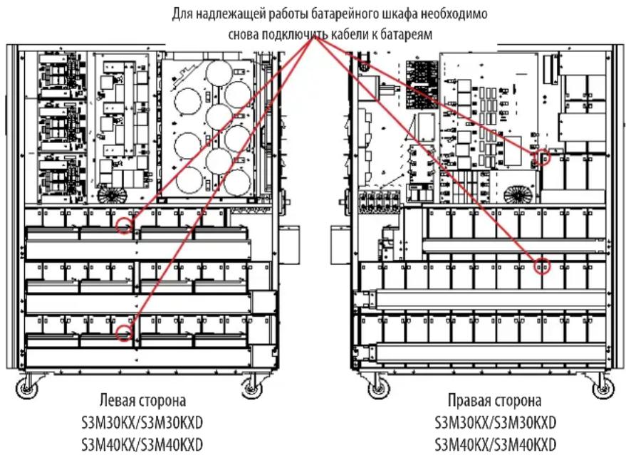
PNC.3.3 PNC.3.4
4)YCTAHOBHTA MeCTo BepxHIOI 60KOBbIe NaHEIN,CHTbIe Ha Wae 2.
5)YCTAHOBNTe O6paTHo HA CBOH MecTa H 3aTAHMe BCE BnHTbI, YkA3aHHbE B n.1, CYCNmEM 1 H-M.
3.3 YctahOBKa BHyTppeHHnx 6aTapeB MoedJx S3M30KX-NIB, S3M30KXD-NIB, S3M40KX-NIB, u S3M40KXD-NIB

BHUMAHNE! BBICOKOE HANPRJXEHNE ONACHO JINK3HNI
Ctporo cobnoidae Bce npdnypeckdeHnnoTexnke 6e3oNaChocTn, n3noKeHHbIe BypkoOBdCTBe noJIb3oBaTea, oOcbeHNO bpa3Je 2.3 PnpdypeckdeHn oTHocntelbo 6atapen
YcTaHOBKa 6aTapei D0JXHa IPOIN3BOIMTBcra TOpIbKO KBaIMnIuPObAHbIMM 3eKtpOExHMkAMN.
Heo6xodmbie 3neMeNTbI:
1) (peiCTBa HINWbUaIbHo 3auHTbI (pe3HOBbIe nepaTK, dN3NeKTPuecKne 60TbI, dN3NeKTPuecKn pe3HOBbl HaonlbHbIK KObpNK np. cornaCHO pa3Deny 2.3 PpynpeXdHn oTHocTeBbHO 6atape).
2) TepMeTmUHbI CBnHcOBo-KnCIOThBHe 6aTapeM (80 wt.): 12 B, 9 A- (VRLA AGM/GEL). BaTapeM OJINKHbI 6bITb Odo6peHbI Ia6opatOpnei No TeXHKe 6e3oNacHOUL 1989, UL CCN: BARZ2.
3) MoTAtxHbI KOMTIeKr Tripp Lite, PN: ACC-0442. IpoBepBe THeHmUe BceX Heo6xOdMhBix DeTaeTbe B MoTAtxHOM KOMTIeKTe. 3ToT KOMTIeKr BkIouaet B ce6b:
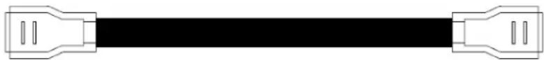
1) CHIMMTE BEXHIOI 60KOBbIE naHEIN, BBiBepHyB IN3 HIX BCE KpeneXHbIE BHTbl.
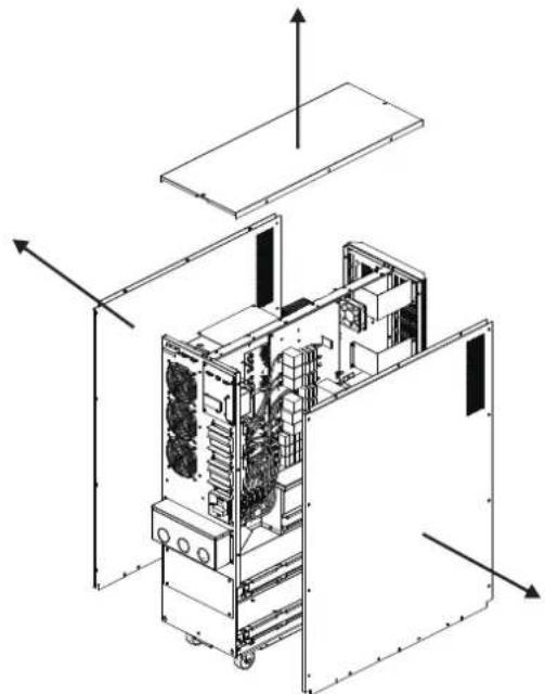
3)YCTAHOBITE 116KIOKB AKKMYIATOPbIX 6bATEe HApyc (L1-a).Bce 6bATEe DOnkHbI paONarTaBC KJIEMMaMM BBepX.
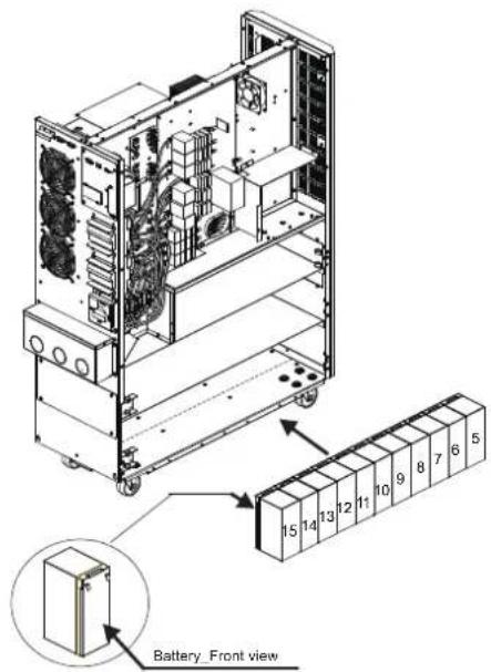
5) UCTAHOBITEpyrhe 960KOB AKKyMnTOpHbIXbATapeHHa npyc (L3-a).Bce 6aTapeHdoXHb paCNOIarTaBC KIIEMMaM HBePx.
2) CHIMMTE CKO6bI dIaI KpENNEHMa 6aTapei c npaBoN nEBoN cToPOH N5I.
4) YCTAHOBITEpyrme 116nokOB AKKMyIaTOpHbIX 6aIapEn HaIpyc (L2-a).Bce 6aIapEn DOJIKNHbI paCNoIarTaCb KNEMMaM BBePx.
3.YctaHOBKa NHaCTpoiKa
6) YCTAHOBITE DpyTNE 11 6nOKOB AKKyMnyTApOpHbIX 6atapeH Ha pyc (L1-b). Bce 6atapen DOJHKbI paCnONaRaTbCA KJIeMMAMM BBepx.
8) YCTAHOBITEpyRHe 860KOB AKKyMnyTOpbIbx 6aTpaeHa apyc (L3-b).Bce 6aTapeNdoHHb paonolarBaC KEMMaMn BBepx.
10) UCTAHOBITEpyTWE 26noka akkyMnyatopbIx 6aTapeH Ha npyc (L6).Bce 6aTapeH DOLXHBpacnonarTaC KNEEMMaHH
7) UCTAHOBITEpytnE 116KOKOB AKKMYIATOPbHx 6aTapeH naPyc (L2-b).Bce 6aTapeWdoJIKNbI paNIOJARATbc KIIEMMaMn BBepX.
9)YCTAHOBITEpyTNE56NOKOBAKKMyIaTOpHBx6aTapeHa npyc(L4H L5).Bce 6aTapeen DOnKHbpaCnOraTaBCa KJIeMMMaMn BBepX
3.YctaHOBKa NHaCTpoiKa
11)YCTAHOBNTHa CBOH MeCTa WcETb CKo6 DnA KpENNEHMA GaTapei, CHATbX B n.2.

12)CnpabOHTcPOHbIbIeOeINHHeNoDBeKLeEMMbHaBcEx6aTapeXnOKa3aHHbIXHmXe,cNOMoCbIO 30OTpeKOBKa6eIa

3.YctaHOBkaHaCTpoiKa
13)Cnomoubko6a6eJIa
7 coednHte 6aTapeN 日51 N 日52
Cnmoosbko6e
6 coeinnHte 6aTaepen N75 n N76.
CnmoosbKa6eBn
5 coeHnHTe 6aTapeu N#67 n N#68.
CnmoosbuKa6eBn
4 coeinnHte 6aTapeN#64 n N#65.
CnmoosbkoKaebna
2 coeINHnTe 6aTapeN #62 n #63.
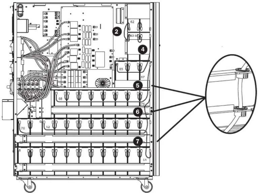
14)CbeBcTcPOHbIbNlcoeMHHTeNoDBeKJIeMMbHaBcEx6aTapexcNmoOpbu2Otpe3koKab6en


3.YctaHOBkaHaCTpoiKa
15) CnmoosbuO nporo Ka6eB 5 coedHHTe 6aTepen N077N078.

16) YctahOBITE npyIe 4 6noka akkymlyaTOpHbIx 6aTapeH h aIpyc (L1). Bce 6aTapeH dIJIKHi paCOnlaTaBc KIeMMMaMn BBepX.
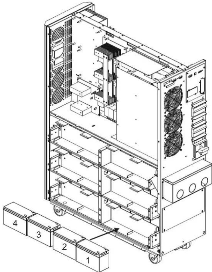
3. YctaHOBKa n HacTpoiKa
17)Cnmoaibko6bien
coeHNHt6aIapEnN#4nN#5.
Cnmoosbko6e
3 coeHNHTe 6aTapeN N3 nN4.
CnmoosbKa6eBn
3 coeINHnTE 6aTapeN N2 nNp3.
CnmooskuKaebn
3 coeHNHtE 6aTapeN N1 n N2.
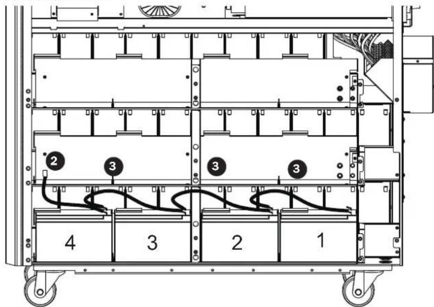
18) yctahOBtne npTyne 4 6noka aKKyMnyIaTOpHbX 6aTapeH h npyc (L2). Bce 6aTapeH dOnJHKbI paCNoIaTBcK NEMMaMn BBepx.
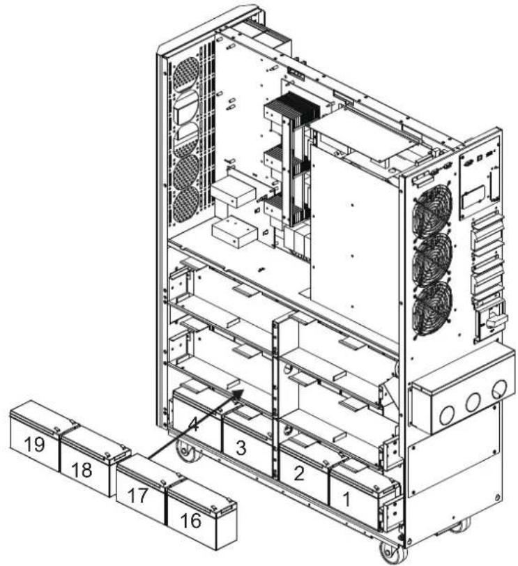
3. YctaHOBKa n HacTpoiKa
19)Cnmooubko6eJIa
2 coeHNHnTe 6aTapeN N19 n N20.
Cnmoosbko6e
3 coeinnHe 6aTapeu N18 n N19.
CnmoosbKa6eBn
3 coeHNHTe 6aTepen N17 uN18.
CnmoosbuKa6eBn
3 coeinnHte 6aTapeu NnN17.
Cnmooubko6a
4 coeinnHte 6aTepen N15 N N16.
20) YctahOBITE npTHe 4 6noka aKKyMnyTAOpHBx 6aTapeH h npyc (L3). Bce 6aTapeH dOJnxHb paCOnaRaTBcKNeMMMaMH Bepx.
3.YctaHOBka NHaCTpoiKa
21)Cnmooubko6a
2 coeHNHTe 6aTapeN N34 N N35.
Cnmoosbko6e
3 coeHNHTe 6aTepen N33N34.
Cnmoosbka6e
3 coeHnHTe 6aTaepen N°32 n N°33.
CnmoosbuKa6bena
3 coeinnHte 6aTaapeu N°31 n N°32.
Cnomoubkokaebna
4 coeinnHte 6aTapeN #30m N#31.
22) YctahOBtHe hCBo MeCTa KPOHHTeHbI dNn KpENHeH6aTapei.
3.YctaHOBka NHaCTpoiKa
23)MnOJIb3yBONbTMeTp,H3MpeBtepa3HOCTbPOTeHuaNoB MExdyNOIOKHTeNbHbIM NOIOC6BaTApEN #20 INOTPUaTeNBbIM NOIOC6BaTApEN #1 (HanpJKeHHe NOCToHHOrTOKaDOnXHO HAOHITbCBAHAna3OHe 240-270 B)
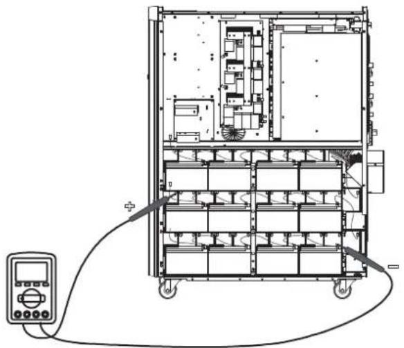
24)NcnoB3y BONbTMepT, H3Mpe TaHocTb noteHuaNoB Mekdy noNoKHTbHbIM noIOOC 6atapEn No40 n OtpuataeNbHbIM noIOOC 6atapEn No21. (HanpJxHeHne noCToHHoro ToKa DoJIxHO HaxOHTbCBA DnAa3OHe 240-270 B)
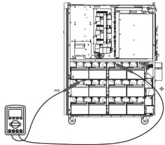
25) NcnoB3y BOnBtMeTp, N3MepBe pa3HOCTb POteHuaNoB MExdy NIOXHTeHBiM NOIocOM 6aTapeN #80 n OTpuataeHBiM NOIocOM 6aTapeN #61 . (HaipxKeHne NoctoHHoro ToKa
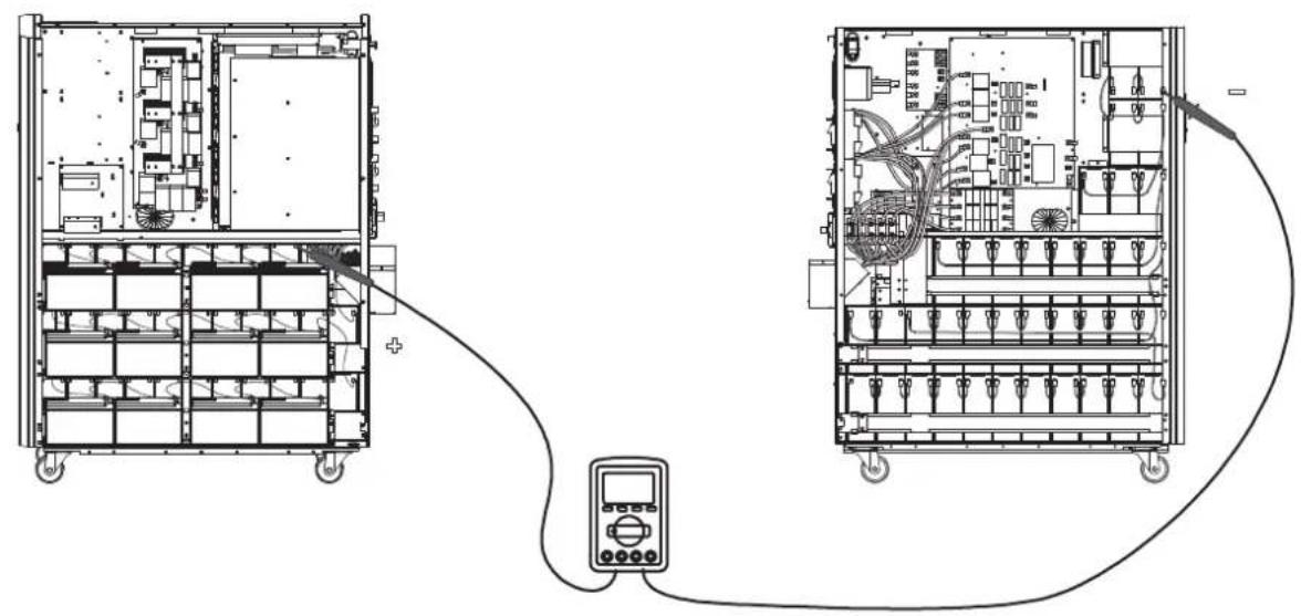
26) NcnoB3y BOnBtMeTp, 3Mepbte pa3nOCTb noteHuaNoB Mekdy nolokntelbHbIM nolocom 6aTapeu N60 m otpuatelbHbIM nolocom 6aTapeu N41. (HanpaeHme noctoHHoro ToKa doJxHO HaxoDttCB Dmaana3OHe 240-270 B)
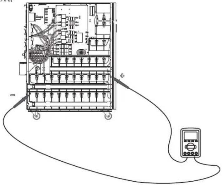
3. YctaHOBKa N HacTpoiKa
27) ⅡIra coeHHeHHa 6aTaape Hcnoh3yTe nnaTy npdoxpaHntene, a TaKke cM. pnc. 3.5, 3.6 n 3.7. IOnHbI cIncoK coeHHeHH mExdy 6aTapeHHnnpctTabneB Ta6nue 3.1.
Ta6nla 3.1 MoTajxHa 7cema 6aTepe nIy MoD. S3M30KX/KXD/NIB u S3M40KX/KXD/NIB
Ta6nua 3.4 BaTapeu H ABToMaTHueCKHe BbIKNoUaTeHn Dn8BaTapeHOrO WkaFa
PnHnnhna hna 3neKtpnueckaa cXema npaannelbno nKnloeHHa (Dna moae S3M30KX, S3M30KXD, S3M40KX, S3M40KXD, S3M30KX/KXD/NIB nS3M40KX/KXD/NIB)
3.YctahOBka nHaCTpoiKa
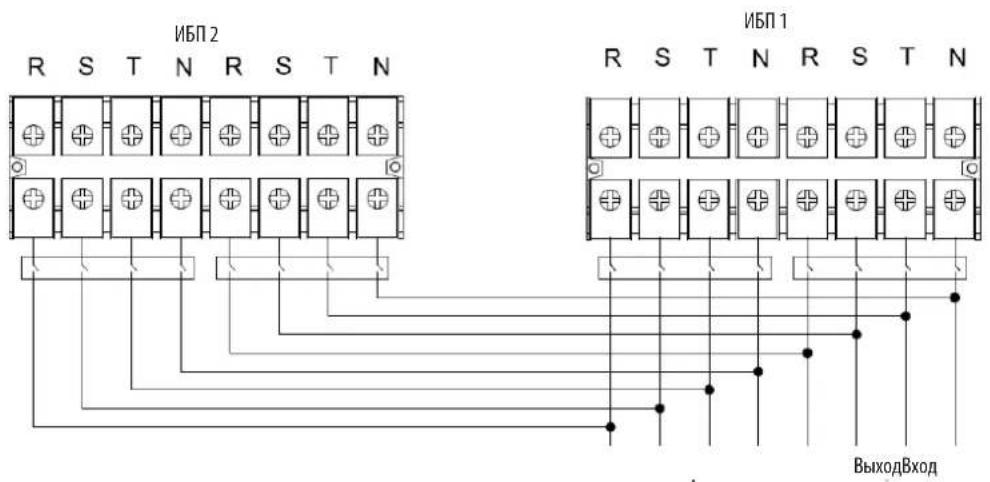
PmHnmaaBna 3eKtpueckcA cxema npanenbHoro noKnouehnna (Ipa moen S3M60KX/KXD u S3M80KX/KXD)
3.6 NpokkoueHne BHeuHHx 6aTapei
16M0eS3M30KX u S3M40KX ochauaTcH aexxho BHytpHeH chtemOaKKymIaTOpbix 6atape. ImaoaeS3M60KX u S3M80KX tpe6yotcBheuHne 6nokn akMyIaTOpbix 6atape. I npDnEHHBaMeHH aBOHOHMHO pa60tB CEX moeHN MOrY HcNoJIb3OBaTBc BHEHNE 6nOKn aKKmyIaTOpbIX 6atape. Hapdy c npDnEHm BpEmH aTOHOHMHO pa60tB, noKnIOueHne DonONHHTe bHbIX BHeHIN 6tape pnpBeTe K yBENHHeHbPemeHH 3apAkn.
Ha npmbednHn HnHex nnnctpaunn noka3aHO MeToonooKeHe pa3bema nnoKIOUeHn BheuHe 6Tapeu K TOMy MBI (Moohocby 30 / 40 kBA), K KOtOpmy NoKnIOuaetcB Heunn bok akymyTApbix 6atape 7. Ha nllnoctpaunn BN3y noka3aHa cxema noKIOUeHn dna moJeem MoOHcTb6n 80 kBA.Cneye Te ykazAHmNo yCTahOBke 6noka akkymyTApbix 6atape, n3NOxENHbM B ero pykoBOCTBe nOb3OBaTeN. Y6eNTecB ToM, rTO Ka6en nnHOCTbO BCTabNEHb CBON pa3beMb. Pn noKIOUeHN 6atape Bo3MOXHO He3NaHTebHo HCKpeHne. 3o ABNeHne CHTaETCA HopMaNBbIM.
He noKIOuaiTe H He oTKIOUaiTe 6nOKn AKKyMnyTOpHbX 6aTaep Bo BpeMa p60b IVB peXmme nIaTHAOn O 6aTaep.
*He 60eep Tpe BheuHmX 6nokOB AkyMnyTOpHyb 6tapeH na KaKdN I5I.
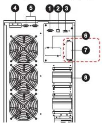
Pa3bemIaI NOKIIoueHnBHeuHero 6noka aKyyMnyTOpHbix 6batae
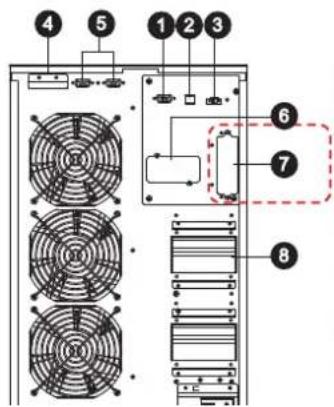
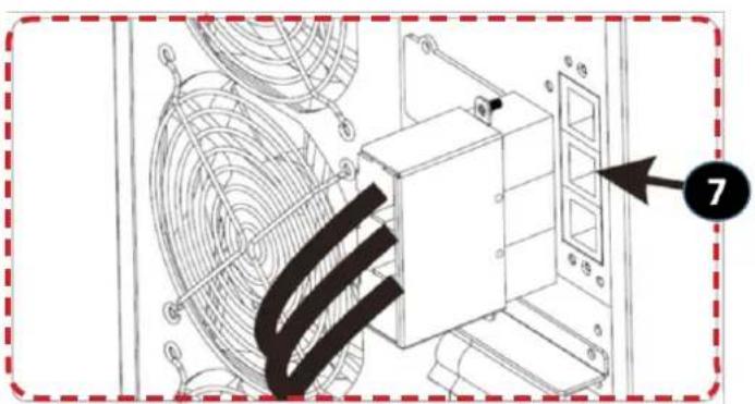
IopKnloueHneBHeuHnx6aTaepeKINbMnO.S3M30kX/KXD/NIBuS3M40kX/KXD/NIB
(ДЯМФ.53M30KX/KXD/NIBиS3M40KX/KXD/NIB)
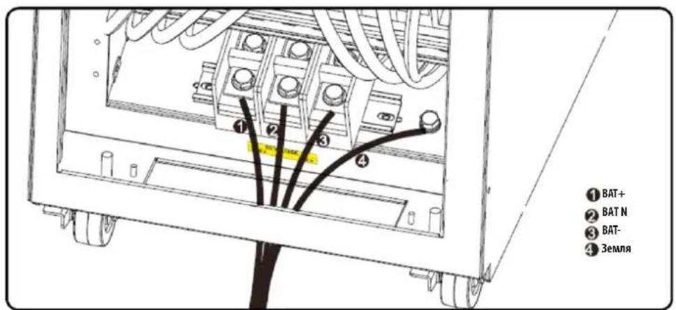
Пдкюченин Всшнихбатарк ИБП мол. S3M60KX/KXD m S3M80KX/KXD
3.YctaHOBKa NHaCTpoiKa
3.7 YctaHOBKa co CqBoeHHbIM BXoJOM NITaHnI NpeMeHHoro ToKa
MoJIeH N5IcO cDBoEHbIM BxOOM NITAHmpeMeHHoro ToKa (o603aueHnKOTopBx coepKaT cyfMnc "KXD") npINBEHeNk 6a3OBoK KOHpyaum C OINHAPHbIM BXoDM NITAHmpeMeHHoro ToKa NocpeCTBOM YCTAHOBKN Tpex 3akOpauHbaIOuXnpeMbYek MekJy BxOOM peMeHHoro ToKa 1 (AC Input 1) nBXoDM nepeMeHHoro ToKa 2 (AC Input 2).PnJKeHaHNmICNoJIb3OBA Tb MoJIe"KXD"co cDboEHbIM BxOOM peMeHHoro ToKa Heo6xoIDMO CHrTB 3TN Pn peMbUKn HblONHtbp3BOkky BxOJa peMeHHoro ToKa 1 n BxOJa peMeHHoro ToKa 2 COOTBETCTBYOUM o6pa3OM.
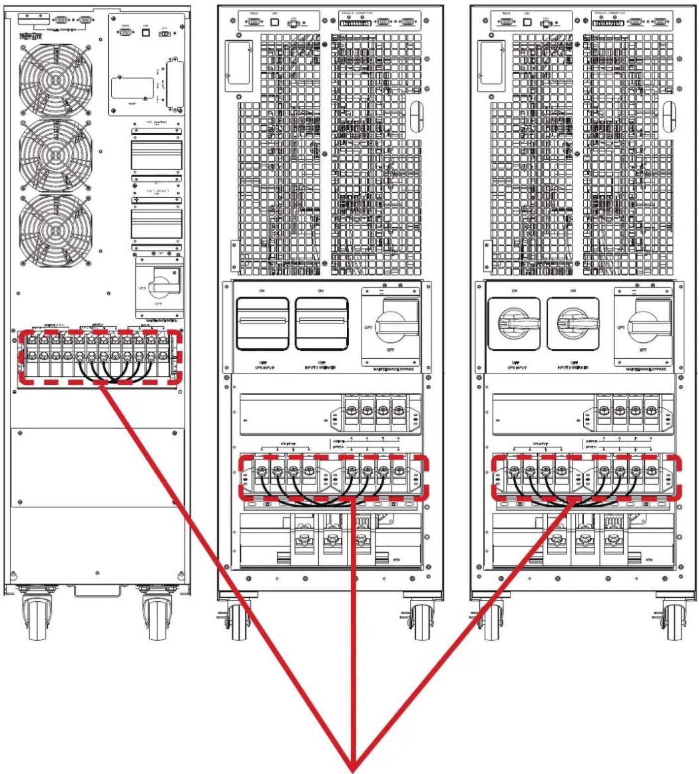
IpeembukmBoMeJXKoCoDboeHHbIMBXOaOMIpeMeHHOToKa. IpmeaHne.BxoDbHeNtpannCOBMeuehbeDpyrCpyromBHytpnKOpNyca.
4.Порадokэкплуataци
4.1PpHnDcTbN KHOKdncn
| Коньк Куншоньhoe Наразаиме | |
| Коньк ON/Enter ("ВКЛ/Bвор") | Б клочени NBП: Дд BA KИчουени NBП нажмite Ha 3у TKY KнОКУ и уderжавaite ee He MeHee 0,5 c.Коньka Enter ("ВВOD"): нажмite Ha 3у TKY KнОКU дд NOДТВЕРЖIDENHЯ BыбраHHо IОПи M MeHNo HAcTpoE.K. |
| Коньka OFF/ESC ("ВыКЛ/OTmeHa") | Быкочени NBП: Дд BA KИчουени NBП нажмite Ha 3у TKY KнОКU и уderжавaite ee He MeHee 0,5 c.Коньka Esc ("OTmeha"): нажмite Ha 3у TKY KнОКU dд BOЗВрATA Bnpedbyduyu prazden MeHHo HAcTpoE.K. |
| Коньka Test/Up ("Tect/Bbepx") | Тстupоване 6Батар: Дд Тстupоване 6Батар в ржIMax OH- naH N Freq. Converter* (ПЕОБР. YACTOTbl) нажмite Ha 3у TKY KнОКU и уderжавaite ee He MeHee 0,5 c.Коньka UP ("ВБерx"): нажмite Ha 3у KнОКU dд OTбраЖEGHЯ Спедуюш eOniN B MeHHo HAcTpoE.K. |
| Коньka Mute/Down ("OTknIOчEHne 3Byka / BnH3") | ОТknIOчEHne 3BykoBoI сгнIHANZaHIM: Дд OТknIOчEHnI 3BykoBOrO сгнIHANa нажмite Ha 3у TKY KнОКU и уderжавaite ee He MeHee 0,5 c.Падрбна Инфорmaци п徳ставлeha в раздeNe 4.4.9.Коньka Down ("Внз"): нажмite Ha 3у TKY KнОКU dд OTбраЖEGHЯ п徳ыduyeш eOniN B MeHHo HAcTpoE.K. |
| Коньк Test/Up + Mute/Down ("Tect/Bbepx + OTknIOчEHne 3Byka / BnH3") | Дд BA xOda/BbIXOda B/ɪz MEHIO нажмite Ha 3у TKY KнОКU onDHBpeMeHNOи Uderжавaite IXe Me He MeHee 1 cekynIb. Падрбна Инфорmaци п徳ставлeha в раздeNe 4.7 MeHIO Setup (Hauahlha yctanobka) |
*PexHM Freq. Converter ("Piope6p, cactoTbI) 03Haaet noctOaHHOe BixIOHoe HapnpaKHeH NocToHHy IbIXoHDHy cactO TY.
4.2 CBeToaNoDhIe HnHkAToPbI N K-NAHeB
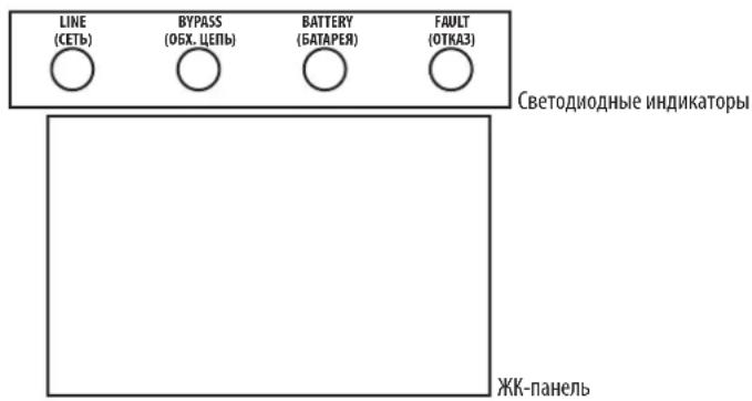
CBeToDnOHDhIE HNIMKaTOpbl:
Ha nepeDnei naHenn yctpoHCTBa pacnnonaIaoTc4 CBeToNIOHbIx HndKAtop, oTo6paKaioux npaoee coToHHe IVI:
4.3BykoBaaCnHaHnaIaIaIaIaIaIaIaIaIaIaIaIaIaIaIaIaIaIaIaIaIaIaIaIaIaIaIaIaIaIaIaIaIaIaIaIaIaIaIaIaIaIaIaIaIaIaIaIaIaIaI
4.7 MeHIO Setup (Haayabha yTaHOBka)
IyBxa/ByxoA B/3 MeHIO Setup (HaaybHa yTaHOBA) OHOBpeMeHHo HAKMTe Ha KhoNKe Test/Up (TeT/Bepx) Mute/Down (OTKn.3Byka/Bn3) MyepKmBaIte Hx He MeHee 1 ckyHbl.
JaHACrpoKnMnONb3yOcTpaNapaMeTpa.Cm.npeCTabHeHHnHKe pcyHok.
Papamtp 1 cnjxnt dnyyctahOBKn BapmHToB nporpaMM. YcTahOBOChIe nporpaMMbI pndCTaJIeHbI B pNpBeDeHHbx HnHex Ta6nuaX.
Ipaamtp 2 n Ipaamtp 3 npdctablaot c6oB onuun nn 3naeHnna Hactpoek Jnna KaKdo nporgaMMbl.
Iinne ot knoaetca uee3 10 MmHyt nocne BblonHeHHnOe HeoTBeN. dHaHnA yHKnBkIOueHa Na octoHHo OCHOBE.
PnmeHne. IaI 3MHeHn pOprpAMm Hn npAeMetpoB nOlyteCk KHONKAMn "Up/Beepx" mDn Down/Bnns
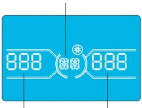
Napametp 1
Napametp 2 Napametp 3
4.Порадokэкплyaтauи
Ipeueheh nporpamM,doctynnbixnna Napametpa 1:
02:Yactota BbIXoHOrTo k
15: PeryunpoBkHa npraKeHn ppeo6pa3ObaTeIa A
HntepcHactpoika
Napamr2: Bb6paBfHKuHAdd (Pn6aBntb) HIN Sub (Y6aBntb) INA KoppeKtpoBKN HAnpJKeHH Npe06pa3oBaTeJI A.*
Napamtp3:ДмаланOH HanpxkeHm coctabnE rO 09,9B npn 3aueHm no ymoJauHIO B.
*BenHnHa npaMeTpA Add (Pn6abntb) nIb Sub (Y6abntb) cooTBeTCTBye YcTaHOBneHHOMy BbxOJHOmy HapJxKeHHIO.
16: Perynnpobka HanpajkeHn ppeo6pa3oBaTea B
InTepeicNaTpoika
Napamtp 2: Bb6paBfynKcHIO Add (Pn6abntb)nn Sub (Y6aBnB) nIe KppeKtpoBKn HnpanJKeHH Npeo6pa30BaTeJI B*.
Napamtp3:Imana3oH HanpXeHH coCTaBnE rTO 0 Do 9,9 B npn 3HaueHH no yMoJUaHHO B.
*npectabneHbBemuHbHnnpaeHnpeobpa3oBateB 6bnyet oobpaKaTcHnno T noa Hnnncsbo Rddnnn SUB.
17: PerynpoBka HanpJxKeHn pneo6pa3oBaTeNa C
HntepcHacptponka
Napamtp 2:Bb6paTb yHKunu Add (Pn6aBntb) mN Sub (Y6aBntb) nKoppeKtnpOBKn HnpanKeHnna pno6pa3oBaTeNa C*.
Napamtp3:MaanaohHnpanxekhencoctabnaetO 09,9B npn3haeynno ymoanuAHO B.
*DnpeTcAsBeHbHnpanjEeHnpeo6pa3obatenaC6yderOt6paKaTbcauNo2noHdnnmboRddnSUB.
18:KannibpoBka HanpIeHnHa BbIXoJe A
Иntepfeic Hactpoika
Napametp 2: Bcerda oTo6paKaet OP.V B KaueCTBe BixOJHO To HnpanKeHn.
Napamr3:0t6paKaet pe3yIbTaB HByTpHeHro N3MepeHnHa npAeHn Ha BxOe A. OH MoKet 6bIt bKan6pOBaH nyTeMa HaaTn KhoNkUp/Bepx HnDown/Bn3 B COOTBeTcBnCpe3yIbTaOM N3MepeHn, NOUYeHbIM C BHeHrO BoNTMePa. Pe3yIbTa KaIIb6PbKn BBODITCR B DeICTBne HkaTHeM KhoNk Enter (BBoD). KaIIb6pOboHyd mAna3OH OrpAHuHBaETcR npedenaM +/-9B.3aФyHKua O6bHNo nCIOb3yeTc Dn CNTcEM C npaJIeNbHbIM NoDKIOueHem.
19:KannibpoBbKa HanpJxKeHnHa BbIXoJe B
HntepcHnC HctponKa
Napametp 2: Bcerda OTo6paKaAeT OP.V B KaueCTBe BixOJHOro HAnpRaeHnna
Napamr3:0t6paKaet pe3yIbTaB HHTpeHHeRo N3MepeHnHa npAkeHn Ha BbXoBe B. OH MOKe 6bIt OTaKl6pObaH nyTeMa HaaTm KONKU Up/Bepx HIn Down/Bn3 B COOTBETCTBN C pe3yIbTaOM N3MepeHn, NOJYeHbIM C BHeHrO BOBtMetpa. Pe3yIbTa KaHbPbKn BBOUITcBA DECTBHe HauKaTHM KONKn Enter (BBo). KaHbPOBuHb IINaHaO hOrpaHmHBaTeC ppeNaM +/-9 B. 3a fHKzua 06bHNo nONb3yeTc dna CNTcM cnapJIeNbHbIM nOdknOueHem.
*I npECTabEnHb BENmHb HnnpJekHb Ha BbXOe B 6yET oTObpaKaTbCa YnCNO 1 noHdnnCbIO
4.Порадokэкплyaтauи
20:Kanib6pObKa HanpIeHnHa BbIXoJe C
HntepcHactpoika
Napametp 2: Bcerda OTo6paKaet OP.V B KaueCTBe BixOHO HAnpAKeHn.
Napamtp 3: OTo6paKaet pe3yIbTaB HHTpeHHeRo h3MepeHnHa npAkeHn Ha BbXoCe C. OH MoKet 6bIt bOtKaIn6pOaH nyTem HaaTm KhoNkUp/Bepx nn Down/Bn3 B COOTBETCTBN C pe3yIbTaOM h3MepeHn, NOJyuHbIM C BHEuHrO BoIbMetpa. Pe3yIbTa KaIIb6pOKn BBOIDTCB DEIcTBNE HauKaTHM KhoNk Enter (BBoD). KaIIb6pOboHbI dIaIaON hOrpaHuaBaTeC npedanm +/-9 B. 3Ta fHyKzua ObSyHIO NcIOb3eYcI Dn CntcE m cnapJIeNbHbIM nOKnIueHem.
*Dn npdctabnnHb BmNHHb HnpanjeknHa Hb bixode C 6ydet otobpaKaTbCnNo 2 noa nAanncbO P.U.
21: Hactpoika zapdHoro toka
InTepeic NaCtpoika
Napametp 2:CHGyka3bIbaeT ha yHKUIO KoppeKTHPOBKN 3apAHOrTOkA.
Napamr3:YCTaHbMaBt 3apnHbTOK. Duaan3oH daHHo HactpoKu:OT 1do4A.3haeHne no ymoJauHHo:2A dna MoJeMouHocTBHO 30K/40K u 4A nla MoJeMouHocTBHO 60K/80K.
30K-40K: KoppeKtpyET 3apAHyb TOK TOBko DnO yDHOH 3apAHyo PnATbI, yCTAHOBHeHHO HA N6Pi. B cIyuae yctahOBKn 6Oonee OHOH 3apAHyo PnATbI daHHa FyHKuHa He paBoTaT.
60K-80K: KoppeKTpyet 3apnHbTOK TOnbKO dIa DByx 3apnHbIX nIaT, yCTAHOBneHHbx HA IVB. B cnyae yctahOBKn 6OJIee dByx 3apnHbIX nIaT daHHa FyHKUHa He pa6oTaET.
PnmeHne. Nocne yBeneHnue HnCn3a 3apnHbNnTnBt Bce YcTaHOBnHbE 3apnHbNnTnBaTb 3apKaHO 6TaPeO c MaKcnMaHbHO MOnIOCTbO, COBTBcTByuoue Toky 4 A. Pnpndarotc Dba Tnna KOMnnkTeoB paoHepnHa 3apnHbNnTnA: nIy I6Pi MoJeNe S3M30KX nS3M40KX (KOMnKeT Tnna CBKT30-40) nIy I6Pi MoJeNe S3M60KX nS3M80KX (KOMmKeT Tnna CBKT30-80).
22:YctaHOBKa KOnuYeCTBa 3apAdbix PnAT
InThepeicn Hactpoika
Napamr2:CHgka3bIbAeTHa yHKUIO KOPpeKIN KOJIueCTBa 3aApIbIX nIaT.
NapamTp 3:YctaHabnBaet KOnuYeCTBo 3apaHbIX pIaT. Duaa3oH NaCToPoiKu: ot 1 Do 3HaueHMe no ymoJUaHmIo: 1.
- 60K-80K:ДeЗардньплatabуcoTbetcTByOT odHоурп.Вслчae уctahOBkn Ha WIlЧуБЕТырEXЗapdHBxПАТ DAHHbI npaMeTpdoJIKeH6bltbyCTAHOBnHa2.BcLnyae yctahOBKnHa WIlшecTNЗapdHBxIIAT DAHHbI npaMeTpdoJIKeH6blt bYCTAHOBnHa3.
PnmeHne. npyBnueHHKoHueCTBa 3apdHbIX pntaDHHb napaMeTp DOJIKeH MeHTBCs COOTBTCTBEHO.
23:HaCtPoiKa pe3eepBnpoBaHna
Hntepfeic Hactpoika
Napametp 2: TOL -oboshaaet konuuectbo IVI. Iana3oH hactpoKn: ot 1 do 3. 3haeHne no ymoanauHno: 1.
Napamr3:RED-0603haaetKoIeCTBOpe3epBbIXbI.Ⅱmana3OHHaCTpoiKn:OT 0do2.3haueHMe noymonHaHMo:0.
PnmeHne. KOnueCTBO, yka3aHHe B HactoKe KaJdoRIOB, doXHO 6bTb paBBHM KOInueCTBy IBN, noKIAuOeHNbIX npaIIeNBHO B cenAX pe3epBPOBaHnA. EcnY cTahOBnHHe KOInueCTBO He paBHO KOInueCTBy IBN B CHTeMe, To IIN pNoaTe npdeynpeHntbn CMnHn.
4.Порадokэкплyaтauи
4.8 OncanHe pa6oHxpeKHMOB/cocToHHN
B npBBeHNO HnKte Tabuue npEcdTabHe HnHofpMaun, BbBODmAm Ha KK-3KpaH Ba3NHybIX pexMx pa60TbH COCTOHHX.
(1)PnHOpMaHbHOpa6oIbIHaeroNaHEnIOncneOaTeBbHOOTobpaKaIOcCeMbKpaHOBCpECTABJIeHMe3BXOHBxHApJXHHaAM (An,bn,Cn),3NHHeHbIXBXOHNbHXapJXHH (Ab,bC,CA)HaactoTb,CMeHHOuXdpyRpyra.
(2) npy yneHn HauahbHn HaCTpoKe CHTeM INPc npaJIeNbHbIM NpOKnIOeHMe OTO6paKaETc OINH DOnONHTeBHyk EKpaH cHaINMbHOo"PAR" B KAcYeTbe NpApMaTePa 2 n npCBOEHbIM HomepOM B KAcYeCTBe PanaMeTpA 3, KaK poka3aHO HIXe HA INIIOCTpaUHK eKpaHa npaMeTPOB npaIIeNBHO rOIOKNIOeHHN. OChOBMy IbI ABOTMaTHeCKn npCBAHbAeTc Homep "001". PeepBbIM INpncBaHbAOTcHomepa "002" INN "003". B IpouceCe paObTu BO3MOxHO dHAMueckoe H3MeHeHne pncBaHbMaBX HmOpob.
3KpaH npaMeTPOB npaJIeIbHOrO noJKnIOUeHnE
5. CpeiCTBa B3aHMoJeICTBnA
Pa3Mepb6atapeHoro shka
12B65/100A·x40wT.
12B40A·u×40wT.
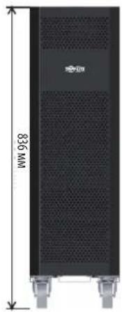
12B9/10A·x80wT.
Modelle: S3M30KX, S3M30KXD, S3M30KX-NIB, S3M30KXD-NIB, S3M40KX, S3M40KXD, S3M40KX-NIB, S3M40KXD-NIB, S3M60KX, S3M60KXD, S3M80KX, S3M80KXD
1111 W. 35th Street, Chicago, IL 60609 USA • www.triplite.com/support
3.5 USV-Parallelinstallation

WARNHINWEIS:
- Table of contents
- Introduction 3
- Important safetywarnings 4
- Installation and setup
- Operation 27
- Communication 48
- 6.Troubleshooting 49
- Storage and maintenance 50
- Specifications 51
- 9.Warranty 54
- Espanol 55
- Françals 109
- Pycckn 163
- Deutsch 217
- Introduction
- Important safetywarnings
- Save these instructions
- 2.1 UPS locationwarnings
- 2.2 Equipment connectionwarnings
- 2.3 Batterywarnings
- 2.4 Transportation and storage
- 2.5 Preparation
- 2.6 Installation
- 2.7 Connectionwarnings
- Before working on this circuit
- 2.8 Operation
- 2.9 Standards
- 3.1 Unpacking and inspection
- Cabling for ups paralleling
- Other accesory and component options available
- Rear panel view - 30K and 40K models
- 3.2 Internal battery connection procedure for S3M30KX, S3M30KXD, S3M40KX, S3M40KXD models
- Danger! lethal high voltage hazard
- Internal battery connection procedure
- 3.3 Installation of internal batteries in S3M30KX-NIB, S3M30KXD-NIB, S3M40KX-NIB, and S3M40KXD-NIB models
- Dangeri lethal high voltage hazardi
- Items needed
- Notes
- 3.4 Single ups installation
- Warning
- 3.5 UPS installation for parallel systems
- 3.6 External battery connection
- 3.7 Dual ac input installation
- Operation
- 4.1 Display button operation
- 4.2 LED indicators and lcd panel
- Led indicators
- 4.3 Audible alarm
- 4.4 Single ups operation
- 4.4.1 Turning on the ups (on-line mode)
- 4.4.2 Turning on the ups without utility power (battery mode)
- 4.4.3 Connecting devices to ups
- 4.4.4 Charging the batteries
- 4.4.5 Battery mode operation
- 4.4.6 Testing the batteries
- 4.4.7 Turning off the ups with utility power present in on-line mode
- 4.4.8 Turning off the ups with no utility power present in battery mode
- 4.4.9 Muting the alarm
- 4.4.10 Operation in warning status
- 4.4.11 Operation in fault mode
- 4.4.12 Transfer critical load from line mode to maintenance bypass
- 4.4.13 Transfer critical load from maintenance bypass to line mode
- 4.5 Parallel ups operation
- 4.5.1 Parallel system initial startup
- 4.5.2 Turning on a parallel system in on-line mode
- 4.5.3 Turning on the parallel system in battery mode
- 4.5.4 Adding a new unit to the parallel system
- 4.5.5 Removing a unit from the parallel system
- Method 1: isolating a single unit from a parallel system
- Method 2
- Warning: (for parallel system setups only)
- 4.6 LCD panel abbreviations
- 4.7 Setup menu
- 02:Output frequency
- 03: Voltage range for bypass
- 04: Frequency range for bypass
- 05:ECO mode enable/disable
- 06: Voltage range for eco mode
- 07: Frequency range for eco mode
- 08: Bypass mode setting
- 09: Maximum battery discharge time setting
- 10: Reserved
- 11: Hot standby function setting
- 12: Neutral loss detection
- 13: Battery voltage calibration
- 14: Charger voltage adjustment
- 15: Inverter-a voltage adjustment
- 16: Inverter-b voltage adjustment
- 17: Inverter-c voltage adjustment
- 18: Output-a voltage calibration
- 19: Output-b voltage calibration
- 20: Output-c voltage calibration
- 21: Current charger setting
- 22:Charging boards number setting
- 23: Redundancy setting
- 4.8 Operating mode/status description
- 4.9 Fault codes - when a con is solid (not flashing)
- 4.10 Warning indicator- when a's flashing
- 4.11 Warning codes - when a con is flashing
- Communication
- 5.1 Smart monitoring slot: snmp monitoring using the webcardlx card or contact closure mangement using relaycardsv (optional cards)
- 5.2 EPO connector
- 5.3 RS-232 port
- 5.4 USB port
- 30kVA and 40kVA models
- 60kVA and 80kVA models
- Troubleshooting
- Storage and maintenance
- 7.1 Storage
- 7.2 Maintenance
- 7.3 Battery
- 7.4 Fan
- Specifications
- Warranty
- 3-Phase ups system limited warranty
- Regulatory compliance identification numbers
- Weee compliance information for Tripp Lite customers and recyclers (european union)
- Articulos necessities
- Pykobodctbo N0lb30BaTeJia
- Copepxahne
- Bbedhene 165
- Baxhble npedynpekdhn no texnke 6e3onachoctn 166
- Yctahobka n hactpoika 169
- Cpectba B3aImoJeCTBn 210
- Bbiabhehne uyctapaehne hncnpabhocte 211
- Xpahenhe n texhnueckoe o6cIyXmbaHne 212
- Texhueckne xapaktepncn 213
- Tapahtnhbie 06a3aTeJbCTBa 216
- English 1
- Français 109
- 1.В蜱てнe
- Dpyrne npednaraemble onu nn komneetyouune
- Dononhtnebna 3apnHa niatn ybenuehhe emkoctn 3apnHoro yctpnoctba
- 3nemEmtbi 3aHne nanei (nla mo, 30K n 40K)
- 3.YctaHOBka nhactpoika
- 3.2IopraoknoiknoueHnBHytpenHH6aTapei moS3M30KX,S3M30KXD,S3M40KX,S3M40KXD
- Bhimahhe! bbicokoe haprjxehne onacho jia XH3HN
- IopraoknoKIOKIOUeHnBHyTpeHHx6aTaPei
- 3.3 Yctahobka bhytppehhnx 6aTapeB moedjx S3M30KX-NIB, S3M30KXD-NIB, S3M40KX-NIB, u S3M40KXD-NIB
- Bhumahne! bbicokoe hanprjxehne onacho JINK3HNI
- Heo6xodmbie 3neMeNTbI
- 3.YctaHOBkaHaCTpoiKa
- Yctahobka n hactpoika
- 3.6 Npokkouehne bheuhhx 6aTapei
- 3.7 Yctahobka co cqboehhbim bxojom nitahni npemehhoro toka
- 4.Порадokэкплуataци
- 4.1PpHnDcTbN khokdncn
- 4.2 Cbetoanodhie hnhkatopbi n k-naheb
- Cbetodnohdhie hnimkatopbl
- 4.3BykoBaaCnHaHnaIaIaIaIaIaIaIaIaIaIaIaIaIaIaIaIaIaIaIaIaIaIaIaIaIaIaIaIaIaIaIaIaIaIaIaIaIaIaIaIaIaIaIaIaIaIaIaIaIaIaI
- 4.7 Mehio setup (haayabha ytahobka)
- 4.Порадokэкплyaтauи
- 02:Yactota bbixohorto k
- 15: Peryunpobkha nprakehn ppeo6pa3ObaTeIa a
- 16: Perynnpobka hanpajkehn ppeo6pa3oBaTea b
- 17: Perynpobka hanpjxkehn pneo6pa3oBaTeNa c
- 18:KannibpoBka hanpiehnha bbixoje a
- 19:KannibpoBbKa hanpjxkehnha bbixoje b
- 20:Kanib6pObKa hanpiehnha bbixoje c
- Hntepchactpoika
- 21: Hactpoika zapdhoro toka
- Intepeic nactpoika
- 22:YctaHOBKa konuyectba 3apAdbix pnat
- Inthepeicn hactpoika
- 23:HaCtPoiKa pe3eepBnpoBaHna
- Hntepfeic hactpoika
- 4.8 Oncanhe pa6oHxpeKHMOB/cocToHHN
- Cpeictba B3aHMoJeICTBnA
- 3.5 Usv-parallelinstallation
- Warnhinweis
Brand : Tripp Lite
Model : S3M40KXDNIB
Category : Inverter