SU5KRT3UX - Inverter Tripp Lite - Free user manual and instructions
Find the device manual for free SU5KRT3UX Tripp Lite in PDF.

User questions about SU5KRT3UX Tripp Lite
0 question about this device. Answer the ones you know or ask your own.
Ask a new question about this device
Download the instructions for your Inverter in PDF format for free! Find your manual SU5KRT3UX - Tripp Lite and take your electronic device back in hand. On this page are published all the documents necessary for the use of your device. SU5KRT3UX by Tripp Lite.
USER MANUAL SU5KRT3UX Tripp Lite
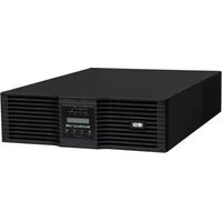
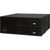
Single-Phase Rack-Mount Online UPS with Built-in LCD Monitoring & Control Screen
Not suitable for mobile applications.
Models:
SU5KRT3UHV, SU5KRT3UHVP, SU5KRT3UX, SU5KRT3UG, SU5KRT3UHW, SU6KRT3UHV, SU6KRT3UHVP, SU6KRT3UX, SU6KRT3UG, SU6KRT3UHW
(Series Number: AG-0358)
1. Overview 2
Parts List 2
Additional Accessory Options 2
2. Important Safety Instructions 2
3. UPS Circuit Block Diagram 5
4. Installation 6
Internal Battery Rotation 6
Rack Mounting 8
Tower Mounting 9
Hardwire Input and Output 10
Wiring Instructions
(Optiona with Select Models)
UPS Input and Output Overview 11
5. Features 11
Front Panel Controls, LEDs and 11
LCD Screen
Rear Panel Features 12
6. Operations 14
LCD Front Panel Display and Controls 14
LED Front Panel Indicators 14
Front Panel Button Functions 15
Home Screen Layout 15
Basic Connection and Start-Up 16
Power Strategy Selection Options 19
Front Panel LCD Selection and 21
Configuration Options
Configuring External Battery Packs 24
7. Optional Connections 25
-
Troubleshooting and Event Log 28
-
Internal Battery Replacement 30
10. Fan Replacement 32
-
Storage and Service 33
-
Warranty and Product Registration 33
Espanol 35
Francais 69
Pycckn 103
NOTE: Exteral bary pack option require configuration using front panel LCD interace or via Tripp Lite's EXTERAL BATTERY CONFIGURATION software.
WARRANTY REGISTRATION
Register your product today and be automatically entered to win an ISOBAR® surge protector in our monthly drawing!

triplite.com/warranty


Manufacturing Excellence
1111 W. 35th Street, Chicago, IL 60609 USA · triplite.com/support
Copyright © 2021 Tripp Lite. All rights reserved. SmartOnline® is a trademark of Tripp Lite. For latest updates, please visit tripplite.com
Overview
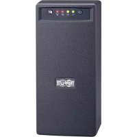
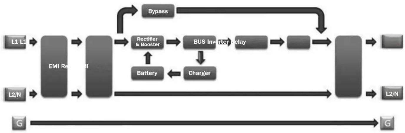
Tripp Lite SmartOnline rack-mount UPS systems with interactive LCD interface feature on-line, double-conversion UPS protection with full-time sinewave output and zero transfer time, making them suitable for all advanced networking applications. Each UPS provides long running battery support with optional extended-run and Web communications ability. Built-in interfaces include Micro-USB, RS-232 serial, Emergency Power Off (EPO), Remote On/Off (ROO) and an RJ-11 smart battery port. The interactive front panel LCD screen provides detailed UPS status, preset and control options. Optional max efficiency and auto-adaptive power strategy options enable high-efficiency operation with reduced power consumption and BTU heat output.
Parts List
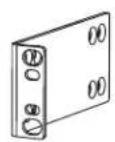
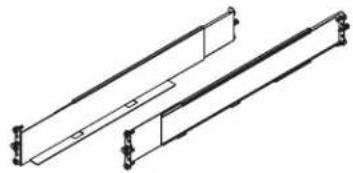
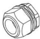
UPS System Bolt-on Mounting Ears (2) 4-Post Rail Kit Hardware Strain Reliefs (2)
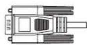
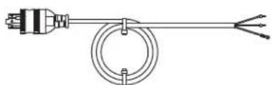
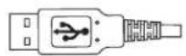
USB Cable (1) RS-232 Cable (1) (Select models) AC Input Power
Cord with L6-30P Plug (1)
Owner's Manual
Optional Accessories (Not Included)
- 2POSTRMKitWM: Supports rack-mount UPS and battery packs in 2-post rack-mount or wall-mount configurations
- 2-9USTAND: Supports rack-mount UPS and battery packs in upright tower configuration
BP192V12RT3US External "SMART" Battery Pack: Extends the runtime of the UPS system

Important Safety Instructions
SAVE THESE INSTRUCTIONS
This manual contains important instructions and warnings that should be followed during the installation, operation, maintenance and storage of all Tripp Lite UPS Systems and Batteries. Failure to heed these warnings may affect your warranty.
Explanation of Symbols

Caution-risk of danger
Hot-overheating may occur

Electrical shock hazard
Protective earth ground

Bonding ground

Recyclable—contains lead

Important Safety Instructions
UPS LocationWarnings
- Your UPS is intended to be used in a temperature-regulated, indoor area that is relatively free of conductive contaminants. Install your UPS indoors, away from excess moisture or heat, conductive contaminants, dust or direct sunlight.
- Ambient room temperature should be between 32^ and 104^ ( 0^ and 40^ ).
- Leave adequate space around all sides of the UPS for proper ventilation.
- The UPS provides the convenience of multiple outlets, but DOES NOT provide surge or line noise protection for connected equipment, when in Bypass Mode.
- Do not mount the unit with its front or rear panel blocked. Mounting in this manner will seriously inhibit the unit's internal cooling, eventually causing product damage not covered under warranty.
UPS Installation and ConnectionWarnings
All Models

CAUTION: Installation should be performed by qualified professional electrical service personnel only.
- Install in accordance with National Electrical Code standards. Be sure to use the proper overcurrent protection for the installation in accordance with the plug/equipment rating.
- Be sure to use an upstream circuit breaker with a C curve.
- Overcurrent protection shall be provided in the end-use application, installed in accordance with local and national electrical wiring regulations.
- Short-circuit backup protection and overcurrent protection is provided by the building Installation, in the hardwire configuration (Bypass and Economy Modes).
Install at a height not exceeding 1 m (3.3 ft.). - Equipment is intended for use on a TN-S power distribution system.
Select Models Come Equipped with an L6-30P Plug

CAUTION: To reduce the risk of fire, connect only to a circuit provided with 30A maximum branch circuit overcurrent protection in accordance with the National Electrical Code, ANSI/NFPA 70 and the Canadian Electrical Code, Part I, C22.1.
- The AC mains L6-30P plug serves as the disconnect device. The electrical outlets supplying power to the equipment must be installed near the equipment and easily accessible. Alternatively, a local disconnect may be provided.
- DO NOT use the hardwire AC supply input option when an L6-30P plug is present. Doing so may cause a catastrophic dangerous situation.
- When the hardwire AC output is used, appropriate output overcurrent protection must be provided.
Select Hardware Models

CAUTION: To reduce the risk of fire, connect only to a circuit provided with maximum branch circuit overcurrent protection in accordance with the National Electrical Code, ANSI/NFPA 70 and the Canadian Electrical Code, Part I, C22.1. See "UPS Input and Output Overview" table in the Installation section for details.
- Use copper conductors with rated 105^ wires only. See "UPS Input and Output Overview" table in the Installation section for recommended input and output configuration.
- For models equipped with a permanent hardwire output connection, overcurrent protection is to be provided in the end use installation. Use output branch-rated overcurrent protection not exceeding the UPS Output rating. When supplying receptacles with lesser branch-rated overcurrent protection, the overcurrent protection should match the receptacle rating.
- In Europe, the circuit breaker must meet the IEC/ EN 60934 standard and have a contact air gap of at least 3mm .
- When the hardwire AC output is used, appropriate OUTPUT OVERCURRENT protection must be provided by the installer. Be sure to use branch-rated circuit breakers that match the rating of the receptacles/equipment being protected. Use circuit breaker(s) with a C curve.
- An appropriate and readily accessible two-pole disconnect device must be incorporated in the fixed wiring.
- In Europe, the AC mains connection is L, N, PE(GND). Make sure to hook up the L to the hot and N to the neutral conductor.
- Never attempt to install electrical equipment during a thunderstorm.
- Do not attempt to use this equipment if any part of it becomes damaged.
- Individual equipment connected to the UPS should not draw more current than the individual outlet's rating.
- The total load connected to the UPS must not exceed the maximum load rating for the UPS.
- Do not attempt to modify the UPS, enclosure, input plugs or power cables.
- Do not attempt to use the UPS if any part of it becomes damaged.

Important Safety Instructions
Equipment ConnectionWarnings
- Do not connect surge protectors or extension cords to the output of your UPS. This may damage the UPS and may affect the surge protector and UPS warranties.
- The total load connected to the UPS must not exceed the maximum nameplate load rating.
- Use of this equipment in life support applications where failure of this equipment can reasonably be expected to cause the failure of the life support equipment or to significantly affect its safety or effectiveness is not recommended. Do not use this equipment within oxygen-enriched atmospheres, or within 0.3m (1 ft.) of a point at which an oxygen-enriched atmosphere is intentionally vented.
Fan Replacement Warning

Make sure UPS is powered down, i.e. turned off prior to fan replacement. Failure to do so may cause overheating and trigger thermal shutdown.

CAUTION: The fan circuitry is not isolated from AC mains. Turn off power to the UPS prior to fan replacement. Fan replacement must be performed by qualified electrical service personnel.
BatteryWarnings
- There are no user-serviceable parts inside the UPS.
- Battery rotation must be performed by qualified electrical service personnel.
- Battery replacement should be performed only by authorized service personnel.
Servicing of batteries should be performed or supervised by personnel knowledgeable about batteries and the required precautions. - When replacing batteries, replace with the same type and number of batteries or battery packs.
CAUTION: Do not dispose of batteries in a fire. The batteries may explode.
CAUTION: Do not open or mutilate batteries. Released electrolyte is harmful to the skin and eyes. It may be toxic.
CAUTION: A battery can present a risk of electrical shock and high short-circuit current. Contact with any part of a grounded battery can result in electrical shock. The following precautions should be observed when working on batteries:
- Remove watches, rings, or other metal objects.
- Use tools with insulated handles.
- Wear rubber gloves and boots.
- Do not lay tools or metal parts on top of batteries.
- Do not short or bridge the battery terminals with any object.
- Remove battery grounds during installation and maintenance to reduce likelihood of shock.
- Remove the connection from ground if any part of the battery is determined to be grounded.

External BatteryWarnings
- Connect external battery ground wire before connecting external battery to UPS.
- For external battery configuration, see the Operations section for options and configuration method. Smart battery packs are automatically detected by the UPS.
Fuses should be replaced only by factory authorized personnel. Replacement fuses should be of the same rating and type. - For extended runtime, only use compatible Tripp Lite battery modules:
BP192V12RT3US External Battery Pack

Important Safety Instructions
Battery Replacement and Recycling

Pb
Tripp Lite products use sealed lead-acid batteries, which are highly recyclable. Refer to your local codes for disposal requirements, Call Tripp Lite at 773.869.1234 or visit tripplite.com/support/recycling-program for more information on recycling the batteries or any other Tripp Lite product.
Tripp Lite offers a complete line of UPS System Replacement Battery Cartridges (R.B.C.).Visit Tripp Lite on the Web at triplite.com/products/battery-finder/ to locate the specific replacement battery for your UPS.
MaintenanceWarnings
- Your UPS does not contain user-serviceable parts. Do not disassemble.
UPS Circuit Block Diagram

Installation
Internal Battery Rotation
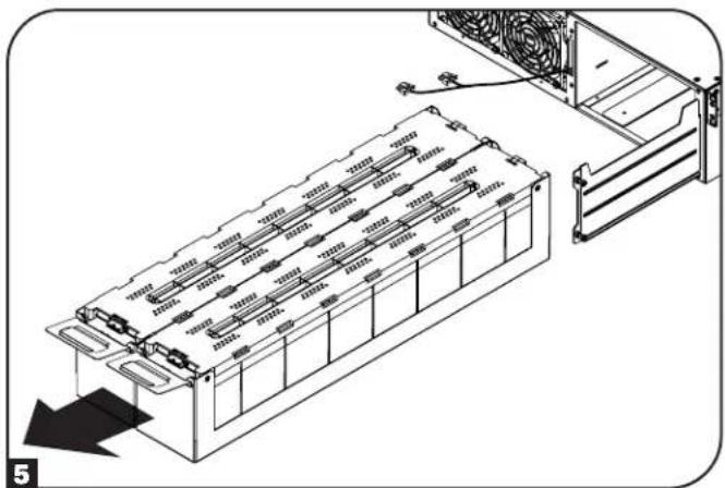
Your UPS ships with the batteries disconnected and in reverse orientation. Before mounting the UPS to your 4-post or 2-post rack, first remove the battery trays and set them aside. To remove the batteries from the UPS, follow the instructions below.

If an external battery pack is to be used, it should be installed first in the lower part of the rack. Be sure to follow instructions for Configuring External Battery Packs in this manual and in the BP192V12RT3US Owner's Manual before proceeding with UPS installation.

WARNING! Battery rotation must be performed by qualified electrical service personnel.
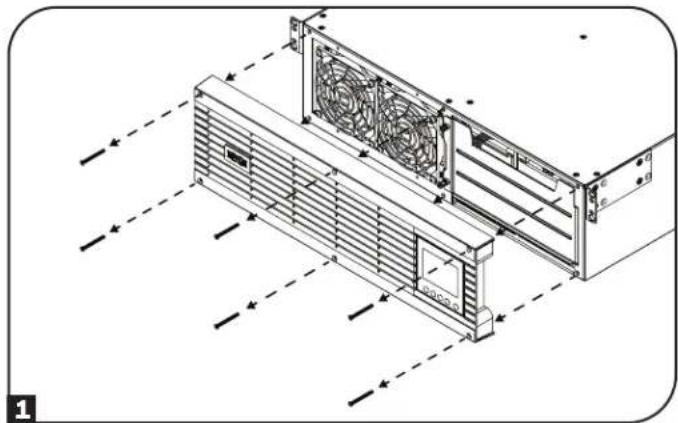
1 Remove the six front screws from the front bezel, then retract the bezel from the UPS. Hang the bezel on the available hook.
Note: The front panel display has an attached ribbon cable that extends from the UPS to the front bezel. Make sure to keep this cable out of the way when opening and closing the battery door, or use a screwdriver to detach the display from the bezel.
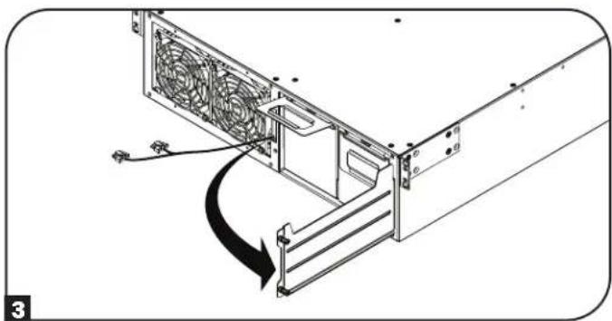
2 Loosen the two captive screws securing the battery door.

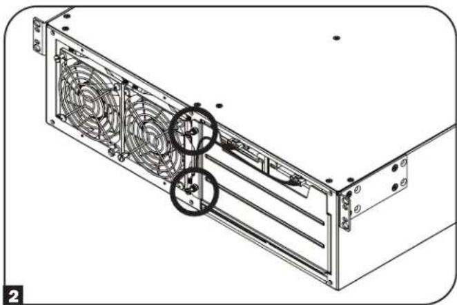
3 Open the battery door. Ensure the Smart battery communication cable is safely out of the way when opening the battery door and when removing the battery trays.
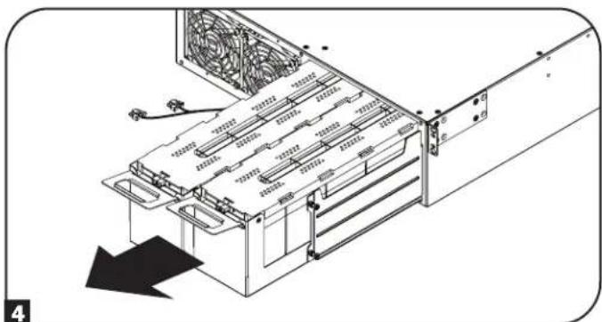
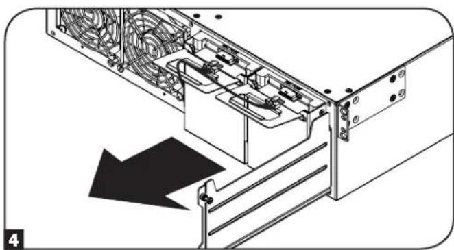
4 Using the handles attached to each tray, remove the battery pack trays. Make sure to remove the handles before rotating the batteries (see next step) and install the handles on the opposite side.
Note: To reduce the weight of the UPS unit during installation, it is recommended you proceed to 4-Post Mounting or 2-Post Mounting instructions in the Rack Mounting section before rotating, reinstalling and connecting the battery pack trays.
Installation
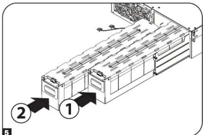
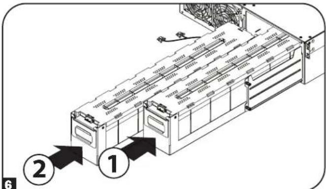
Each battery tray uses a blindmate DC connector. Position each battery tray so the red and black DC connector end is facing towards the rear of the UPS and the communication port is facing toward the front of the UPS. Starting with the right side battery tray, insert the battery pack tray, making sure it protrudes slightly from the UPS. Repeat for the left side battery tray.
Note: For better connector access, attach the cables before the battery packs are fully inserted into the UPS.
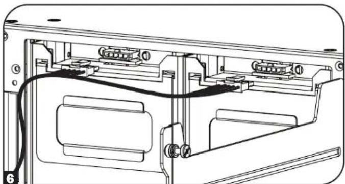
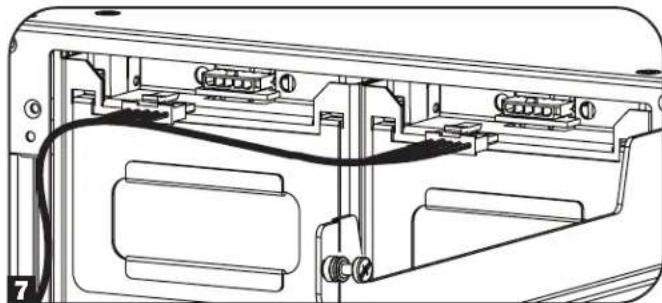
6 Connect the battery communication cable to each battery tray and push the battery trays completely into the UPS.
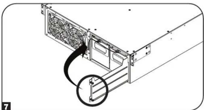
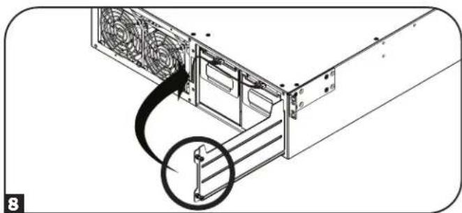
7 Close the battery door and secure by tightening the captive screws.
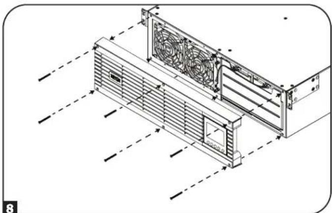
8 Reattach the front bezel to the UPS and secure with the screws removed in step 1.
Installation
Rack Mounting
Mount your equipment in either a 4-post or 2-post rack or rack enclosure. The user must determine the fitness of hardware and procedures before mounting. If hardware and procedures are not suitable for your application, contact the manufacturer of your rack or rack enclosure. The procedures described in this manual are for common rack and rack enclosure types and may not be appropriate for all applications.
CAUTION: The equipment should be installed onto the rack rails at a height < 1 m (36 in.).

If an external battery pack is to be used, it should be installed first in the lower part of the rack. Be sure to follow instructions for Configuring External Battery Packs in this manual and in the BP192V12RT3US Owner's Manual before proceeding with UPS installation.
4-Post Mounting
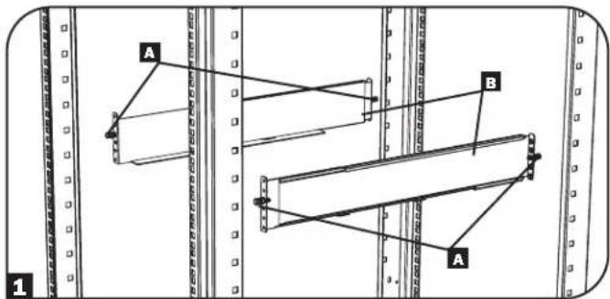
1 The included plastic pegs A will temporarily support the empty rack-mount shelves B while you install the permanent mounting hardware. Insert a peg into the third hole from the top on the front end of each bracket. On the rear end, insert a peg into the center hole. (Each front bracket has 6 holes and each rear bracket has 5 holes.) The pegs will snap into place.
After installing the pegs, expand each shelf to match the depth of your rack rails. The pegs will fit through the square holes in the rack rails to support the shelves. Refer to the rack unit labels to confirm that the shelves are level in all directions.
Note: The support ledge of each shelf must face inward.
2 Remove the pegs at the front end of each bracket. Secure the shelves B to the mounting rails permanently using the included screws and cup washers C as shown. Place 2 screws at the front of each rail (4 total) and 2 screws at the back of each rail (4 total). Tighten all screws before proceeding.
Note: The rear pegs can be left in for installation, but the front ones must be removed before the bracket is secured by screws.
WARNING!
Do not attempt to install your UPS until you have inserted and tightened the required screws. The plastic pegs will not support the weight of your UPS.
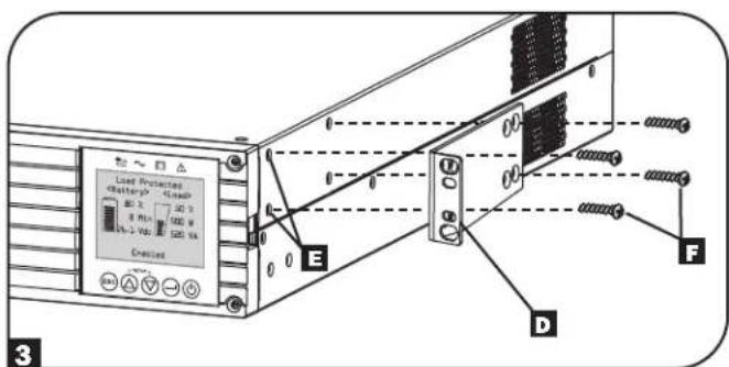
3 Attach your UPS's mounting brackets D to the forward mounting holes E of the UPS using the included hardware F. The mounting bracket "ears" should face forward.
Note: It is recommended you remove the UPS internal batteries prior to installation. Doing so will remove excess weight and allow for safer handling.
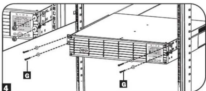
4 With the aid of an assistant, lift your UPS and slide it into the shelves. Attach the UPS mounting ears to the front mounting rails with user-supplied screws and washers 6. Tighten all screws securely.
Note: To install battery pack trays inside the UPS, refer to instructions 5-8 in the Internal Battery Rotation section.

Installation
2-Post Mounting
If you mount 2U UPS models in 2-post racks, they require the addition of a Tripp Lite 2-Post Rack-Mount Installation Kit (model: 2POSTRMKITWM, sold separately). See Installation Kit owner's manual for installation procedure.
Tower Mounting
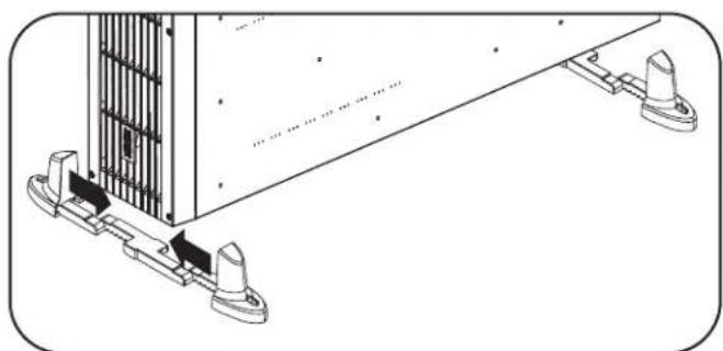
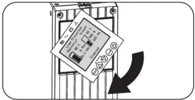
Your UPS can be mounted in an upright tower position with optional base stands sold separately by Tripp Lite (model: 2-9USTAND). When mounting the UPS on adjustable base stands, make sure the LCD panel is facing toward the top.

WARNING!
All UPS systems are extremely heavy. Use caution when lifting and mounting. User must properly stabilize the UPS when lifting and mounting.
The LCD panel may be rotated for easier viewing while the UPS is upright. To rotate, insert a small screwdriver or other flat-edge tool into the slots on any side of the LCD panel. Pop the panel out, rotate accordingly and snap it back into place.

WARNING: Display circuitry is not isolated. Display rotation must be performed by qualified electrical service personnel.
EXTERNAL BATTERY CONFIGURATION NOTE
If external battery packs are to be used with this UPS, install them following the mounting/installation documentation included with each battery pack.
These SmartOnline UPS systems support automatic detection of up to four compatible Tripp Lite Smart battery packs. Each Smart battery pack includes a wired data connection that enables automatic detection and configuration for up to four Smart external battery packs to the UPS. If more than four external battery packs need to be configured, all packs must be configured via the Tripp Lite external battery configuration software connecting though the UPS serial port. In this configuration, do not connect the Smart battery communication cables to any of the external battery packs.
Installation
Hardwire Input and Output Wiring Instructions (Optional with Select Models)
Note: The tightening torque is 1N· m (10 lb·in.).
CAUTION: This type of connection must be performed by qualified professional electrical service personnel only. When making connections, check that the mains power to the UPS is OFF. Connect the ground wires from the cables to the chassis ground lug. Always connect the ground wire first.
Be sure to observe the Input Line Configuration, Breaker and wire AWG as outlined in the UPS Input and Output Overview table, detailed in this section.
Note: Select models include an AC input cord with L6-30P plug. If this AC cord is to be used, the UPS input/output power capacity ratings will change. See the UPS nameplate for more information.
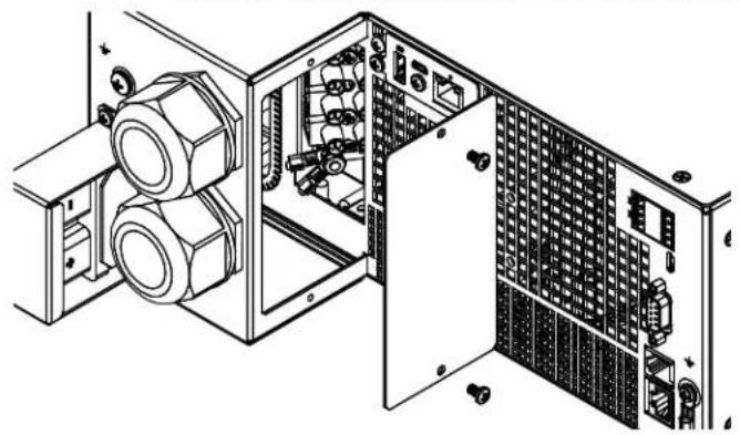
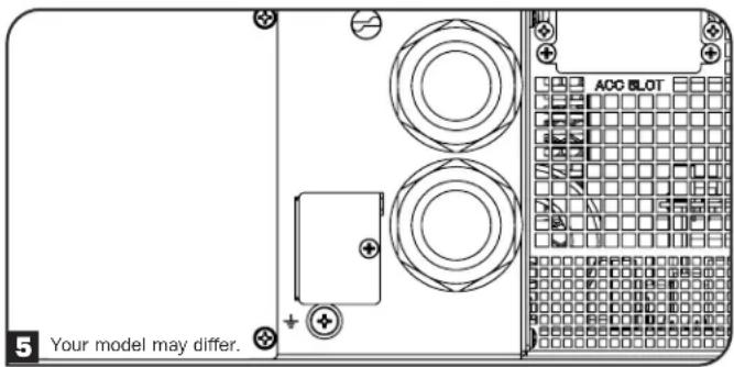
- Remove the access cover located on the right side of the Hardwire In/Out knockouts (shown below), to access the terminal block. Note: A label describing terminal connections can be found on the back of the access cover.
- Remove the appropriate knockout sizes for the hardwire input and output connections.
- Install and secure the included or user-provided strain relief connectors to the hardwire enclosure.
- Pass the cable through the strain relief.
Note: The Output strain relief is on top and the Input strain relief is on the bottom.
- Install each wire to the terminal block, as indicated below. (See note below regarding tightening torque specifications.)
- Tighten the strain relief.
Hardwire In/Out with Strain Relief Input and Output Terminals
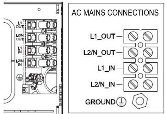
Note: The tightening torque is 1 N·m (10 lb·in.). The included ground lug needs to be added to the ground stud as shown. The ground wire for equipment should fit the #8 stud with an outer diameter of 8.71 mm and an inner diameter of 4.3 mm.
Installation
UPS Input and Output Overview
| Model Name | Input Connection | Input Line Configuration | Building Breaker C-Curve Input AWG (mm 2) | Receptacle Plate Configuration |
| SU5KRT3UHV Hardwire | L1, L2/N, PE(GND) 40 8 (6) | |||
| L6-30P L1, L2/N, PE(GND) 30 10 (4) | ||||
| SU5KRT3UHVP L6-30P | L1, L2/N, PE(GND) 30 10 (4) | |||
| SU5KRT3UX Hardwire L, | N PE(GND) 40 8 (6) | |||
| SU5KRT3UG Hardwire L1, L2/N, PE(GND) 40 8 (6) | ||||
| SU5KRT3UHW Hardwire | L1, L2/N, PE(GND) 40 8 (6) None | |||
| SU6KRT3UHV Hardwire | L1, L2/N, PE(GND) 50 6 (10) | |||
| L6-30P L1, L2/N, PE(GND) 30 10 (4) | ||||
| SU6KRT3UHVP L6-30P | L1, L2/N, PE(GND) 30 10 (4) | |||
| SU6KRT3UX Hardwire | L, N, PE | 50 6 (10) | ||
| SU6KRT3UG Hardwire L1, L2/N, PE(GND) 50 6 (10) | ||||
| SU6KRT3UHW Hardwire | L1, L2/N, PE(GND) 50 6 (10) None |
Features
Before installing and operating your UPS, familiarize yourself with the locations and function of the features of each component.
Front Panel Controls, LEDs and LCD Screen
The graphical LCD on the front panel contains a wide range of UPS operating conditions and diagnostic data. It also displays UPS settings and options when viewing the UPS setup screens. The five buttons below the LCD can be used to navigate the various information, configuration and UPS control screens by following the on-screen prompts and selection options. Additional LED indicators above the LCD screen also provide at-a-glance status of AC input source, availability of output, battery status, and warning/fault status.
See Operations section for detailed descriptions of LCD functions, buttons and LEDs.
Features
Rear Panel Features
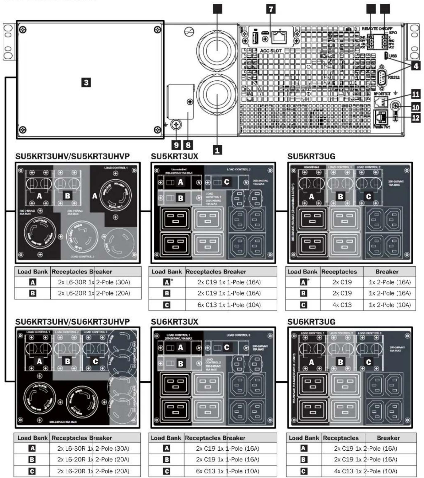
*Uncontrolled Load Bank
Features
AC Input Connection (varies by model): This connects to AC power via an attached power cord or hardwire connection.
Note: SU5KRT3UHV and SU6KRT3UHV models include an optional input cord. SU5KRT3UHVP and SU6KRT3UHVP models include a pre-installed input cord.
AC Hardware Output Connection (optional on select models): This connects to an AC load via hardwire connection (See Hardwire Output Wiring Instructions for more information.
Note: The total load connected to the UPS must not exceed the maximum nameplate load rating.
3 AC Receptacles (varies by model): These output receptacles provide connected equipment with pure sine-wave AC output during normal operation and battery power during blackouts and severe brownouts. The receptacles are divided into load banks, as described on the unit. Using PowerAlert software and cabling, load banks may be individually turned off and on from a remote location, allowing users to reset or reboot connected equipment.
Note: The total load connected to the UPS must not exceed the maximum nameplate load rating.
Communications Ports: These ports (USB or RS-232) connect your UPS to any workstation or server. Use with Tripp Lite's PowerAlert Software and included cable to enable your computer to automatically save open files and shut down equipment during a blackout. Also use PowerAlert Software to monitor a wide variety of AC line power and UPS operating conditions. Consult your PowerAlert Software manual or contact Tripp Lite Customer Support for more information. The 9-pin RS-232 port also supports dry-contact communications. See USB & RS-232 Dry Contact Communications in the Optional Connections section for installation instructions.
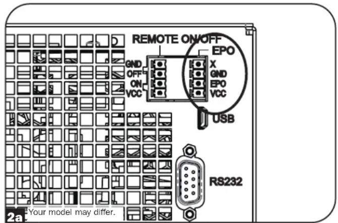
EPO (Emergency Power Off) Port: Your UPS features a port that may be used to connect the UPS to a contact closure switch to enable emergency shutdown of your UPS. Make sure to use the pins on the right terminal block labeled for EPO. See Optional Connections section for details.
Remote On/Off: The UPS includes a port that may be used to connect the UPS to a contact closure switch to remotely turn off the UPS. Make sure to use the terminal block on the left side labeled for remote On/Off connection. See Optional Connections section for details.
Accessory Slot: Remove the small cover panel from this slot to use optional accessories to remotely monitor and control your UPS. Visit triplite.com to see a full list of accessories, as well as a wide variety of network management and connectivity products.
External Battery Pack Connector: Your UPS features a robust internal battery system. Adding external batteries will increase runtime and recharge time. See Additional Accessories (Optional) in the Overview section for compatible models and Configuring External Battery Packs section under Operations section for configuration instructions.
Note: Do not connect or disconnect battery packs when the UPS is running on battery power.
9 DC Ground Screw: Use this to create a ground connection between the UPS and an attached external battery pack.
Chassis Ground Screw: Use this to connect any equipment that requires a chassis ground.
External Battery Pack Detection Port: For external batteries with communication built-in, plugging the battery communication cable into this port will allow the UPS to automatically detect smart battery packs. See the Configuring External Battery Packs in the Operations section for configuration instructions.
2 Parallel Port: Reserved for future use.
Operations
This section explains how to use your Tripp Lite Online UPS System, including front-panel LCD operation, operating modes, UPS startup and shutdown, transferring between modes, setting power strategy, and configuring bypass settings, load segments and battery settings.
LCD Front Panel Display and Controls
A 5- button graphical LCD screen with additional LED indicators on the front of the UPS that provides information on UPS status, load level information, event information, measurements, settings and a wide variety of UPS configuration and power strategy options.
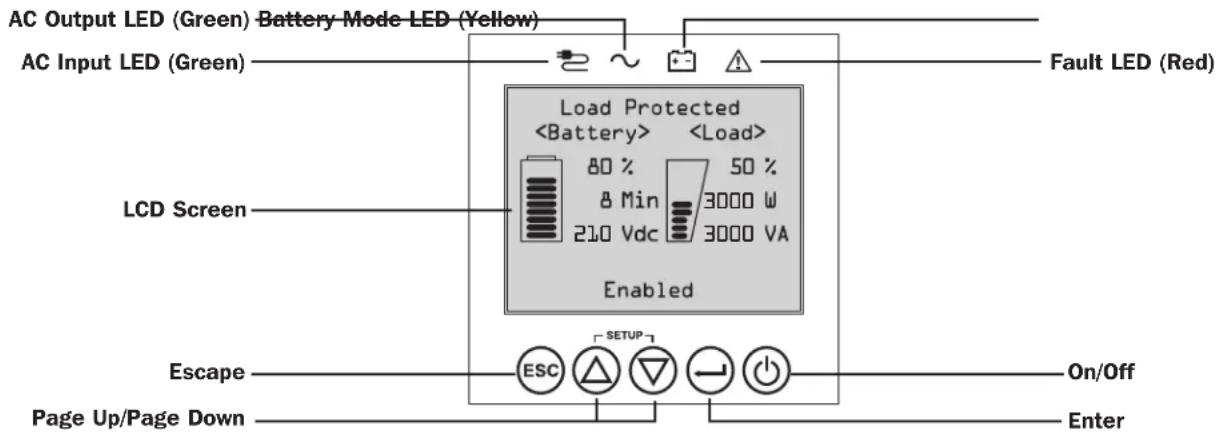
LED Front Panel Indicators
There are 4 LEDs above the front panel LCD screen that offer information on AC INPUT, BYPASS, AC OUTPUT, BATTERY MODE and UPS FAULT status.

AC INPUT indicator
On AC input is available AND AC input is WITHIN the configured ECONOMY / BYPASS mode range. When this LED is ON SOLID, AC input is of adequate quality for UPS operation in BYPASS or ECONOMY MODE.
- Flashing AC input is available AND AC input is OUTSIDE the configured BYPASS mode range.
- When this LED is ON FLASHING, AC input is not of adequate voltage or frequency for UPS operation in BYPASS or ECONOMY MODE.
Off AC input is NOT available.
When this LED is OFF, AC input is not available.

AC OUTPUT indicator
On UPS AC output is ON
UPS output is available at the UPS output receptacles.
Off UPS|AC output is OFF
UPS AC output is not available.

BATTERY MODE indicator
On UPS is running in battery mode
UPS batteries are discharging as the UPS runs in battery mode. Also lights momentarily during self-test operation.
Flashing|UPS is running in battery mode - Low battery warning
UPS batteries are discharging as the UPS runs in BATTERY mode and are becoming low. The indicator will flash at 2-second intervals to report LOW BATTERY and 0.5-second intervals to report BATTERIES ARE NEAR FULLY DISCHARGED and the UPS is near shutdown.

UPS FAULT indicator
On UPS is experiencing a pre-defined fault state
See front panel display for explanation of error state or code information. See on-screen instructions and manual for troubleshooting tips.
Off Normal
UPS is not reporting fault conditions when this indicator is OFF.
Operations
Front Panel Button Functions
There are 5 front panel buttons that offer UPS control and configuration options. To navigate the various information, configuration and UPS control screens, use the 5-button front panel interface and follow the on-screen prompts and selection options.

Power On / Off Button: This control offers three main functions: Power-On, Power-Off and Clear UPS Fault.
To turn the UPS ON into a protected operating mode, press and hold this button for 3 seconds as the UPS is connected to input AC power. Release the button when the alarm begins to sound and the UPS will startup into the last configured power strategy.
To "cold start" the UPS ON into battery mode during power failure conditions, press and hold this button for 3 seconds. Release the button when the alarm begins to sound and the UPS will startup in battery mode.
To turn the UPS OFF as it's running in battery or protected mode, press and hold this button for 3 seconds. Release the button when the alarm begins to sound. The UPS will turn off AC output. Once AC output is off, disconnect input power to the UPS and the UPS will power off completely.
To CLEAR UPS FAULT, press and hold this button as directed on-screen for 3 seconds. The UPS will clear the fault conditions and return to standby or bypass mode.

ENTER Button: This control is used to make selections, confirm options and move forward to the next selection as the UPS is configured in setup mode. Press this button as directed on-screen in Setup mode to Enter, Confirm or Move Forward in the configuration process.

UP / DOWN Buttons: These controls offer two main functions: "Up" and "Down" directional control, plus enter / exit setup mode (when pressed simultaneously). These buttons are used to navigate setup-mode menu options and scroll up or down to view screen contents as necessary.

To ENTER or EXIT UPS SETUP MODE, press these two buttons simultaneously for 3 seconds. Release the buttons when the alarm begins to sound. The UPS will automatically enter setup mode if both buttons are pressed during LCD display modes. The UPS will automatically exit setup mode if both buttons are pressed as the UPS runs in UPS setup mode.

ESCAPE Button: This control offers three main functions: Alarm Cancel, Clear Fault and Back / Cancel operations. To CANCEL UPS ALARM, press this button. If a new alarm condition occurs, the alarm will sound again.
To CANCEL or GO BACK ONE LEVEL, press this button as directed on-screen in Navigation and Setup modes.
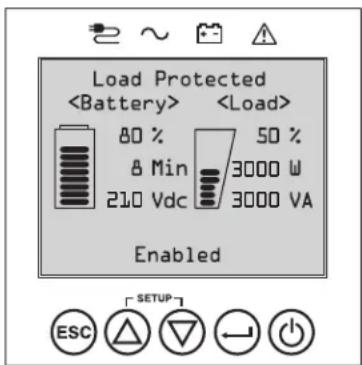
Home Screen Layout
The UPS front panel LCD screen is set up to provide continuous UPS operating information using NORMAL MODE and BATTERY MODE home-screens that continuously report operating mode, protection status, power strategy and a number of battery and load-level operating parameters.

Normal Mode Home Screens
Operations
Basic Connection and Start-Up
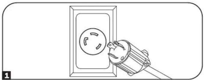
1 Connect your UPS to electrical service
Your UPS must be connected to a dedicated circuit of sufficient amperage. L6-30 models require a 30A building installation breaker. For Hardwire models, refer to the Installation section, UPS Input and Output Overview Table and rating on the UPS for details.
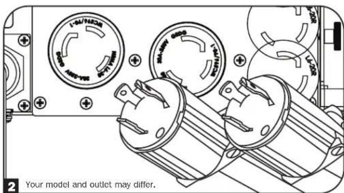
Plug your equipment into the UPS
When input power is applied, the UPS will go into Standby Mode and the batteries will charge.
Your UPS is designed to support network, server and computer equipment only.
Note: If the equipment is to be load controlled, make sure to plug equipment into a load-controlled bank.
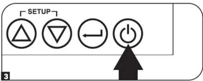
3 Turn your UPS on
Press and hold the POWER button for 3 seconds and release as the alarm begins to sound.
4 Select your Language
When your UPS is powered up for the first time, the INPUT AC LED will light up and the front panel LCD screen will request a language selection.
Using the UP / DOWN buttons 空 , select your language preference, then press the NEXT button.
The interface will confirm your selection and provide options to go back (press BACK or to go to the next step (press NEXT).

Operations
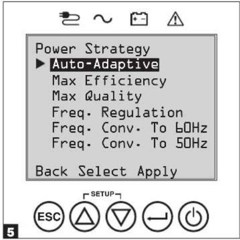
Select your Power Strategy
Next, the UPS will prompt you to pick the desired POWER STRATEGY.
Using the UP / DOWN buttons, select your POWER STRATEGY preference and press the APPLY button.
See the Power Strategy Selection Options and UPS Operating Modes sections under the Operations section for operating characteristics of each power strategy.
Select your Password
Next, the UPS will prompt you to pick the desired PASSWORD.
Using the UP / DOWN buttons, select the first digit of your desired password and press the NEXT button to advance to the second digit. Repeat for digits 2 through 4.
Note: To quickly set the password to "0 0 0 0" press the NEXT button 4 times.
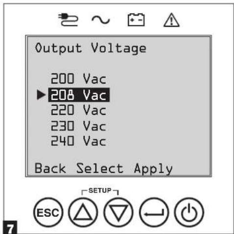
7 Select UPS Output Voltage
Next, the UPS will prompt you to select the desired OUTPUT VOLTAGE.
Using the UP / DOWN buttons, select the UPS output voltage, then select APPLY.

Operations
Select UPS Battery Age Alert
Next, the UPS will prompt you to select the timing of the Battery Age Alert notification. You can select between 12-60 months. The factory default setting is Disabled.
Using the UP / DOWN 念 buttons, select the timing of the battery age alert in months, then press APPLY.
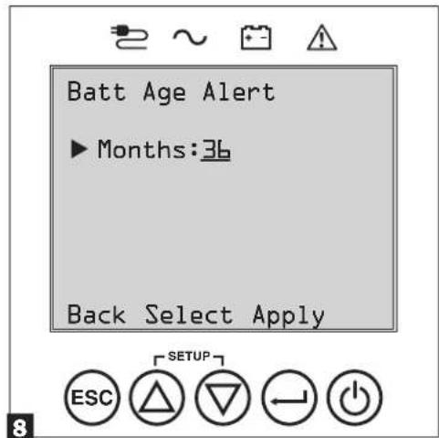
Range: 12 to 60, Default: Disabled
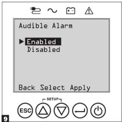
9 Select Audible Alarm ENABLED / DISABLED status
Next, the UPS will prompt you to select the alarm ENABLED / DISABLED status.
Using the UP / DOWN 4 buttons, select the alarm ENABLED / DISABLED status, then press APPLY.
Note: Disabling the alarm prevents the audible alarm from sounding during power failures and UPS fault conditions only. The alarm will still "chirp" to confirm operator input via the front panel LCD navigation buttons when the alarm is set to disable.
The UPS will then go through a series of diagnostic checks before turning on output power. Once the UPS reports the operating status of NORMAL / LOAD PROTECTED with the configured POWER STRATEGY enabled, your UPS can immediately be put into service to provide reliable protection from a wide variety of power problems.
Operations
Power Strategy Selection Options
Tripp Lite SmartOnline LCD UPS systems offer several built-in power strategy options that enable the UPS to optimize performance to meet user needs for MAXIMUM POWER QUALITY, MAXIMUM EFFICIENCY, and FREQUENCY REGULATION or FREQUENCY CONVERSION operation. An additional AUTO-ADAPTIVE power strategy combines the benefits of high-efficiency and maximum power quality. Each power strategy option enables the UPS to automatically shift between specific operating modes as power and UPS status dictates. Available power strategy options include:
- Auto-Adaptive Power Strategy enables the UPS to automatically switch between ONLINE MODE and ECONOMY MODE as dictated by the quality and reliability of UPS input power. If the UPS does not experience a power failure in a week's time (not including UPS self-test) the UPS will automatically switch to ECONOMY MODE. If a power failure occurs, the UPS will maintain output in BATTERY MODE. When power is restored, the UPS will repeat the cycle by running in ONLINE MODE until there are no power failures for one week's time. Auto-bypass mode is available during UPS failure modes when AC input is within the bypass range.
- Max-Efficiency Power Strategy enables the UPS to run continuously in ECONOMY MODE anytime incoming AC power is within the configured bypass low/high voltage range. If UPS input voltage is outside the configured bypass range, the UPS will automatically switch to ONLINE MODE until AC input voltage is restored within the configured bypass voltage range. This is similar to Auto-Adaptive Power Strategy, except transfer to ECONOMY MODE is immediate as voltage levels recover. There is no one-week time period of power failure free operation required in order for the UPS to return to ECONOMY MODE operation. Auto-bypass mode is available during UPS failure modes when AC input is within the bypass range.
- Max-Quality Power Strategy enables the UPS to run continuously in ONLINE MODE the entire time incoming AC power is within the range for online mode operation. The UPS will remain operating continuously in Online Double-Conversion mode, providing the highest quality output power with zero transfer time. Auto-bypass mode is available during UPS failure modes when AC input is within the bypass range.
- Frequency Regulation Power Strategy is similar to Max-Quality Power Strategy, except the UPS will actively regulate output frequency within +/- 0.5Hz of the 50 or 60Hz nominal frequency measured on startup. The UPS will remain operating continuously in Online Double-Conversion mode, providing the highest quality output power with zero transfer time.
Note: Auto bypass during a fault is available. Bypass is not available when the UPS is in Off Mode.
- Frequency Conversion to 60 Hz & Frequency Conversion to 50 Hz Power Strategies are similar to Max-Quality power strategy, except the UPS will actively regulate output within +/- 0.5 Hz of the 50 Hz (Freq. Conv. to 50 Hz setting) or 60 Hz (Freq. Conv. to 60 Hz setting). Auto-bypass is not available in FREQUENCY CONVERSION mode. Typical applications include converting 50 to 60 Hz (or 60 to 50 Hz) for sensitive electronic devices.
Note: Maximum power supported in Frequency Conversion mode is derated by 30% . Auto bypass during a fault is not available.
UPS Operating Modes
Tripp Lite SmartOnline UPS systems are able to automatically switch between operating modes under conditions specified in the configured Power Strategy. The UPS continuously indicates status using front panel LEDs and the interactive LCD viewing screen.
- Battery Mode is the UPS system's automatic response to power failures and voltage variations outside of the online voltage range. In BATTERY MODE, the UPS maintains sine wave AC output power from battery reserves. Once power is restored, the UPS will return to the protected operating mode as dictated by the configured power-strategy and input power conditions.
- Online Mode (also known as ONLINE, DOUBLE CONVERSION MODE) offers the highest level of UPS equipment protection. In ONLINE MODE, the UPS actively regenerates power from AC to DC, then from DC to AC to provide continuously regulated AC output within 2% of the selected nominal output voltage with zero transfer time as the UPS switches between ONLINE and BATTERY modes.
- Economy Mode offers power saving operation with the highest level of UPS operating efficiency. In ECONOMY MODE, the UPS saves energy by turning off the online, double-conversion process whenever input power is within the ECONOMY MODE voltage range. If line voltage or frequency falls outside of the ECONOMY MODE, the UPS will respond by automatically switching to ONLINE MODE until line voltage recovers.
Frequency Regulation Mode gives the UPS the ability to correct frequency variations present on UPS input power. See Power Strategy Selection Options section for details. - Frequency Conversion to 60Hz and Frequency Conversion to 50Hz Modes give the UPS the ability to convert frequency from 50Hz to 60Hz (or 60Hz to 50Hz ). The output frequency is fixed at 60Hz or 50Hz , based on the selected frequency setting. The UPS will accept input frequency from 40 - 70Hz and convert, as needed. See Power Strategy Selection Options section for details.
Note: Maximum power supported in Frequency Conversion mode is derated by 30%.
- Bypass Mode offers filtered and unregulated power to connected equipment.
Operations
Power Strategy Operating Features and Supported UPS Operating Modes
The configured UPS Power Strategy provides a framework for UPS operation as it switches between operating modes as dictated by power events and UPS status. Each Power Strategy offers a unique set of operating parameters that the UPS adheres to in order to meet user preferences for high performance or high efficiency. Additional frequency regulation and conversion options are also available for advanced applications. The chart below lists the UPS operating modes supported for each Power Strategy option.
| UPS OPERATING MODES UPS automatically switches operating modes as dictated by the configured power strategy, current power and UPS status conditions. | |||||
| Support for ONLINE MODE | Support for ECONOMY MODE | Support for BATTERY MODE | Support for AUTO-BYPASS | ||
| POWER STRATEGY SELECTION OPTIONS Your power strategy selection enables the UPS to switch between operating modes as described. | AUTO ADAPTIVE UPS runs continuously in ECONOMY MODE after running in ONLINE MODE for one continuous week without a power failure. | YES. When input is within the ONLINE voltage range, but outside the BYPASS voltage range, and after AC power is restored. | YES. When input is within the ECONOMY MODE voltage range and there are no power failures for one week. | YES. YES. In the event of | UPS inverter fault while input voltage is within the BYPASS voltage range. |
| MAX. QUALITY UPS runs in ONLINE MODE continuously to maintain the highest quality output power for connected equipment. | YES. When input is within the ONLINE voltage range. | NO. YES. YES. In the event of | UPS | inverter fault while input voltage is within the BYPASS voltage range. | |
| MAX. EFFICIENCY UPS runs in ECONOMY MODE full time when input is within the bypass range. | YES. When input is within the ONLINE voltage range, but outside the BYPASS voltage range. | YES. When input is within the ECONOMY MODE voltage range. | YES. YES. In the event of | UPS inverter fault while input voltage is within the BYPASS voltage range. | |
| FREQUENCY REGULATION UPS regulates output to within ±0.5 Hz of nominal. | YES. When input is within the ONLINE voltage range.* | NO. YES. YES. In the event of | UPS | inverter fault while input voltage is within the BYPASS voltage range. | |
| FREQUENCY CONVERSION TO 60 Hz UPS converts to 60 Hz (±0.5 Hz). | YES. When input is within the ONLINE voltage range.** | NO. YES. NO. | |||
| FREQUENCY CONVERSION TO 50 Hz UPS converts 60 Hz input to 50 Hz (±0.5 Hz). | YES. When input is within the ONLINE voltage range.** | NO. YES. NO. | |||
- LCD displays FREQUENCY REGULATION as the operating mode with derating information.
** LCD displays FREQUENCY CONVERSION as the operating mode with derating information.
Operations
Front Panel LCD Selection and Configuration Options
| MAIN MENU / SUBMENU DISPLAY / SETTING OPTIONS DISPLAY / SETTING DESCRIPTION | ||
| STATUS | ||
| Load Status • Load level (%, kW, kVA, A, PF) | Available capacity (%, kW, kVA) | UPS load percent (%), kilowatt (kW), kilovoltamp (kVA), amp (A) & power factor (PF).UPS capacity available in percent (%), kilowatts (kW)& kilovoltamps (kVA). |
| In/Out Status • Input voltage & frequency | (Vac, Hz)Output voltage & frequency (Vac, Hz)Load Group 1 (On, Off)Load Group 2 (On, Off)Load Group 3 (On, Off) | Displays UPS input and output status information for input / output voltage (Vac), frequency (Hz) and outlet group power status (On/Off) information. |
| Energy Status • Efficiency (%) | Avg. Power (kw/hr.)Configured power strategy | Displays UPS efficiency percentage (%), connected equipmentkilowatt hour consumption (kw/hr.) and configured power strategy. |
| Battery Status • Battery model & serial number | Installed (mm/dd/yyyy)Expires (mm/dd/yyyy) | Displays Battery Pack model number & serial number (Tripp LiteSMART BATTERY PACKS) only, installation date and user configuredexpiration date. |
| Power Flow Chart • View UPS operationa flow chart Displays UPS operating mode in a graphical flow chart. | ||
| CONTROL | ||
| Start Batt. Test | Initiates a manual battery test | Initiates a momentary UPS battery self-test with immediate Pass/Fail results. |
| Reset Fault State | Resets any fault state messages | Use this option to clear UPS fault messages. |
| Auto Batt. Testing | Set regular battery self-test interval0 Disable0 4 weeks (factory setting)0 13 weeks0 26 weeks | Use this option to initiate automatic UPS battery testing at regular intervals. |
| EVENT LOG | ||
| On Batt. Events | Event counter(UPS On-battery events only)Total minutes (total minutes ofon-battery mode operation)Most recent power failure (date)Months until battery replacement alert(months)Event details (date, time &description for the last 20 logged events) | Displays a summary of all ON-BATTERY events where the USSP switched to battery mode in response to a protected condition.Event details lists the last 20 battery events. As additional alerts occur, the oldest records will be automatically removed. |
| All Events | Event counter (all events)Most recent event (date)Date time log | Displays a summary of all Recorded events. Event details lists the last 20 events. As additional alerts occur, the oldest records will be automatically removed. |
| SETTINGS | ||
| Basic setup | SystemCurrent date (display, set date)Current time (display, set time)Audible alarm (enable, disable)Language (select) | Displays, sets and resets date, time, audible alarm status andlanguage settings.Note: Audible Alarm DISABLE setting prevents power fail andoperating fault alarms only, the UPS will always "beep" to confirmthe UPS is accepting user input from the front-panel LCDnavigation buttons.Note: The current date and current local time are reported directlyfrom the remote management card. |
| Output voltage200208220230240 | Use the SETTINGS / BASIC / OUTPUT VOLTAGE option to display orset the nominal UPS output voltage (changes take effect on nextrestart). | |
Operations
| MAIN MENU / SUBMENU DISPLAY / SETTING OPTIONS DISPLAY / SETTING DESCRIPTION | ||
| SETTINGS | ||
| Basic setup(continued) | Power strategy:· Auto-Adaptive· Max Efficiency· Max Quality· Freq. Regulation· Freq. Conversion to 60 Hz· Freq. Conversion to 50 Hz | Use the SETTINGS / BASIC / POWER STRATEGY option to display or set the UPS Power strategy.See Power Strategy Selection Options section under the Operations section for more info on the available power strategy options. |
| Battery:· Battery configuration· External Batt· Battery Age Alert | Use the Settings/Basic/Battery option to view external battery installed and its expiration dates, along with replacement battery cartridge information.See Operations/Configuring External Battery Packs for information on how to configure external battery packs.Battery Age Alert enables setting the duration for the battery replacement reminder. The factory default setting is Disabled. | |
| Advanced setup | System:· Display brightnesso Higho Medium (factory setting)o Low· Backlight dim: Enter 10-120 seconds (factory setting is 60 seconds)· Password: Set your 4 digit password (factory setting is 0000)· Factory reset (reset all UPS preferences to factory settings, including battery configurations)Note: When executed, the card will reboot. | Use the SETTINGS / ADVANCED / SYSTEM option to set the display brightness, the display backlight dim time-out, password or factory reset options. |
| In/Out:· Overload Alert Lvl: Enter a value 5-105% (factory setting is 105%) | Use SETTINGS / ADVANCED / IN-OUT for these options: Sets the UPS output load percentage before an overload alert is sent. | |
| Conf. Fault Action (UPS response to fault) o Go to Bypass (factory default) o Go to Standby | Sets the UPS response to fault conditions that require the UPS to exit double-conversion mode. GO TO BYPASS option maintains AC output (so long as input voltage is within bypass high/low limits). GO TO STANDBY option causes the UPS to turn off output AC in response to fault conditions. | |
| · Bypass Low Limit: Enter a value -5% to -20% (factory setting is -15%) | Specifies the lowest acceptable input voltage for bypass operation. | |
| · Bypass High Limit: Enter a value +5% to +20% (factory setting is +15%) | Specifies the highest acceptable input voltage for bypass operation. | |
| On/Off:· Cold Starto Enable (factory setting)o Disable | Use SETTINGS / ADVANCED / ON-OFF for these options:Enabling Cold-start allows the UPS to be manually turned on into battery mode during a power failure. | |
| · Auto Restarto Enable (factory setting)o Disable | Enabling Auto_restart allows the UPS to automatically turn back on into a protected operating mode when power is restored. | |
| · Auto Restart Delayo Enter: 0 to 60 seconds (factory setting is 0 seconds) | Auto_restart delay forces the UPS to wait 0-60 seconds after power is restored before automatically restarting.Requires that Auto_restart when power is restored be enabled. | |
| · Energy Savingo Enter: 0-100%o Disable (factory setting) | Energy saving enables the UPS to automatically shutdown when the output load is less than the selected percentage continuously for 5 minutes. | |
| · Off Modeo Standbyo Bypass (factory setting) | Off mode setting of BYPASS allows the UPS to provide unregulated line power within configured bypass low / high limits to be available at the output of the UPS when it is turned off. | |
| · Min. Batt to Restarto Enter: 10-90%o Disable (factory setting) | Minimum battery charge level to restart forces the UPS to wait until batteries have recharged to the selected percentage before automatically restarting.Note: UPS can be manually started using the power button If battery is below the minimum battery restart threshold.Requires that Auto_restart when power is restored be enabled. | |
Operations
| MAIN MENU / SUBMENU DISPLAY / SETTING OPTIONS DISPLAY / SETTING DESCRIPTION | ||
| SETTINGS | ||
| Advanced setup(continued) | On Battery:Low Batt. Alert○ Enter: 10-90% (factory setting is 20%) | Enables the UPS to send a low-battery alert as batteries discharge to the selected charge level during a power failure. |
| Timed Shutdown○ Enter: 15, 30, 45 sec., 1-30 min.○ Disable (factory setting) | Timed shutdown sets the maximum amount of battery runtime in seconds or minutes the UPS will provide during a power failure.Use the DISABLE setting for the longest possible battery runtime. | |
| Low Battery Shutdown○ Enter: 5-100%○ Disable (factory setting) | Low battery shutdown sets the maximum amount of battery discharge before the UPS shuts down due to low battery. The setting of DISABLE allows the batteries to discharge to 0% before shutdown. | |
| On Batt. Beep Delay○ Enter: 0-120 seconds(factory setting is 5 seconds) | The "Beep Delay" setting allows the audible alarm to be delayed up to 120 seconds to prevent the audible-alarm from sounding in response to short duration power failures. | |
| Shutdown Completion○ Required (factory setting)○ Interrupt OK | The UPS will communicate shutdown messaging to connected systems prior to UPS shutdown. The setting of INTERRUPT OK will interrupt shutdown messaging if power is restored after shutdown messaging is sent. | |
| DB9 Settings:· DB9 Settings○ Output pins 1&5- On battery (factory default)- On bypass- Output on- Low battery (battery mode only) | The UPS will signal the selected condition by shorting pins 1 and 5 on the DB9 port. The max voltage and current flow through this dry contact connection is 30VDC 10mA. | |
| ○ Output pins 8&5- On battery- On bypass- Output on- Low battery (battery mode only-factory default) | The UPS will signal the selected condition by shorting pins 8 and 5 on the DB9 port. The max voltage and current flow through this dry contact connection is 30VDC 10mA. | |
| ○ Input pins 3&9- Shutdown (battery mode only-factory default)- Output off- Reboot- Output on- Power Toggle | The UPS will perform the selected action when pins 3&9 are shorted on the DB9 port for at least 4 seconds.For the Reboot option (output off for 30 seconds before reboot):Note the pins must be shorted for at least 4 seconds to perform the reboot. The reboot happens at exactly 4 seconds. If the pins continue to be shorted for more than 4 seconds, no further action should be taken. The UPS takes no action on release of the short.The Power Toggle option is intended to keep the unit powered on whenever the pins are not shorted and powered off whenever the pins are shorted. Note this input cannot power on the unit from an off state unless valid AC is applied (this function will not impose a coldstart). To power on, the pins must be not shorted for at least 4 seconds and AC must be valid. To power off, the pins must be shorted for at least 4 seconds.The UPS will perform the selected action if the USB signal from a connected device is lost in line power mode for the duration selected. | |
| ABOUT | ||
| UPS Information UPS model number, US$ Serial number,UPS installed date | UPS installed date is automatically set by the unit after 2 hours of continuous operation. | |
| Network ID Web management accessory card firmware,IPv4 address, IPv6 address, MAC Address | ||
| Firmware UPS firmware versions | ||
| Mobile Access - Direits user to the SNMP card interface. The URL is secure | HTTPS. | |
| DOCUMENTATION | ||
| Documentation QR code - Direits user to product documentation on the Tripp Lite website. | ||
Operations
Configuring External Battery Packs
Tripp Lite SmartOnline UPS systems support the connection of external battery packs to enable extended-run UPS operation. In order for the UPS to provide efficient charging levels and accurate runtime predictions for optimal network runtime prior to sending auto-shutdown messaging, external battery packs need to be configured to the UPS upon installation.
There are two methods available to configure external battery packs to the UPS, depending on battery pack selected and quantity added to the UPS. Some battery pack configurations may require the use of more than one configuration method.
Configured AUTOMATICALLY (Using SMART Battery Packs) Or Using EXTERNAL BATTERY CONFIGURATION SOFTWARE
UPS supports automatic detection of up to 4 SMART BATTERY PACKS connected to the UPS.
External Battery Configuration software can be used to configure the UPS for any supported quantity of SMART & NON-SMART external battery packs.
Tripp Lite SMART Battery Packs include a wired data connection that enables automatic detection and configuration for up to 4 SMART Battery Packs to the UPS. Tripp Lite Legacy NON-SMART battery packs are also supported for extended runtime applications, but require user configuration through the use of EXTERNAL BATTERY CONFIGURATION SOFTWARE.
Configuring SMART and NON-SMART BATTERY PACKS
Adding up to 4 SMART BATTERY PACKS to the UPS
Up to 4 SMART battery packs can be connected to each UPS for fully automatic detection and configuration. SMART battery packs include a wired data connection that connects to the UPS Battery Pack Detection port for automatic recognition and configuration by the UPS.
To configure the UPS for use with up to 4 SMART BATTERY PACKS, just connect the included POWER and DATA cables between the UPS and the first SMART BATTERY PACK. Then connect the POWER and DATA cables for additional SMART BATTERY PACKS to the one ahead of it. The UPS will automatically detect and configure up to 4 SMART BATTERY PACKS to the UPS.
Adding more than 4 SMART BATTERY PACKS to the UPS
SmartOnline UPS systems support automatic detection of up to 4 SMART BATTERY PACKS as described above. If more than four battery packs need to be configured, all packs must be configured via BP config software. In this configuration, do not connect the smart battery cable to any of the external battery packs.
Optional Connections
Your UPS will function properly without these connections.
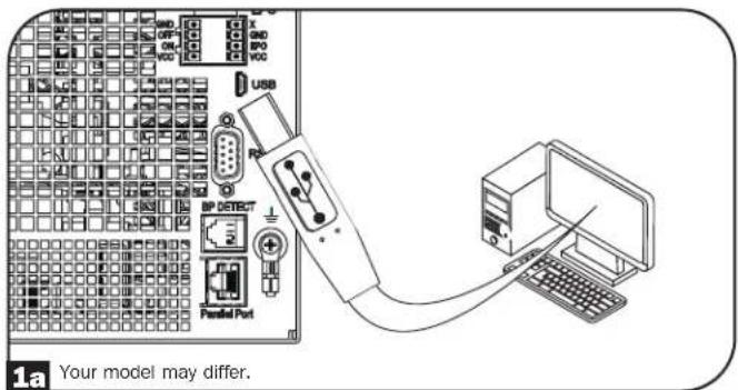
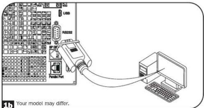
USB and RS-232 Dry Contact Communications
Use the included USB cable (see figure 1a) and/or RS-232 serial cable (see figure 1b) to connect the communication port of your computer to the communication port of your UPS. Install on your computer the Tripp Lite PowerAlert Software appropriate to your computer's operating system. Consult your PowerAlert manual for more information.
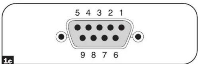
RS-232 dry contact communications are simple, but some knowledge of electronics is necessary to configure them. The RS-232 port's pin assignments are shown in the diagram. If the UPS battery is low, the UPS sends a signal by bridging pins 8 and 5. If utility power fails, the UPS sends a signal by bridging pins 1 and 5. To shut the UPS down remotely, short pin 3 to pin 9 for at least 4 seconds. Additional functions of these pins can be configured through the LCD or via Web management accessory card communication.
| PIN | Assignment Description | |
| RS-232 Dry Contact | ||
| 1 Utility Fail (Open Collector) | ||
| 2 UPS TxD | ||
| 3 UPS RxD Remote Shutdown (5-12V) | ||
| 4 Reserved Reserved | ||
| 5 GND GND | ||
| 6 Reserved Reserved | ||
| 7 | ||
| 8 Low Battery (Open Collector) | ||
| 9 +12V (1KΩ source) | ||
| Rating and characteristics of pin 1 and 8 to GND | ||
| Parameter Value | Conditions | |
| Maximum collector voltage | 30V | |
| Maximum collector current | 10mA | |
| Maximum reverse collector voltage | -5V | |
| Maximum leakage current | 0.1μA | Collector voltage = 20V, pin function is not active |
| Typical voltage drop | 0.5V | Collector current = 5mA, pin function is active |
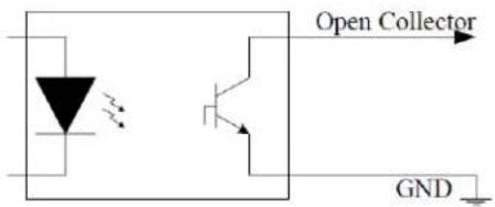
Open Collector Circuit
Optional Connections
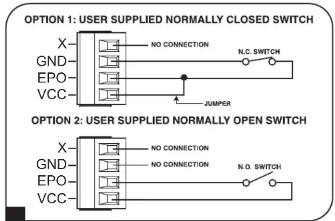
EPO Port Connection
This optional feature is only for those applications that require connection to a facility's Emergency Power Off (EPO) circuit. When the UPS is connected to this circuit, the UPS goes into fault standby. Connect the EPO port of your UPS (see 2b) to a user-supplied normally closed or normally open switch according to the circuit diagram (see 2b).
Note: The 4-pin terminal block supports wire gauges from 14-30 AWG with a strip length of 7mm . The M2 terminal screws should be tightened between 0.22 0.25Nm . If a non-latching EPO switch is used, the EPO must be held for minimum of 1 second. This does not apply to a latching EPO switch.
UPS state when asserting EPO with valid AC input present:
| AC Output LCD Screen Status LEDs Status USB Serial SNMP | ||||
| Off EPO Active Only | AC Input Indicator is On. | Off Off Off | ||
To restart the UPS after EPO assertion with valid AC input present:
- Verify that the EPO assertion has been removed or cleared.
- Press and hold the POWER ON/OFF button until it beeps. Now the UPS will start back up in one of the pre-configured normal operating modes.
UPS state when asserting EPO without valid AC input present (Battery Mode):
| AC Output LCD Screen Status LEDs Status USB Serial SNMP | |||||
| Off EPO Active Off Off | Off | Off | |||
To restart the UPS after EPO assertion:
- Verify that the EPO assertion has been removed or cleared.
- Press and hold the POWER ON/OFF button until it beeps. Now the UPS will restart to either Battery Mode or the preconfigured normal operating mode (if AC power is present).
Optional Connections
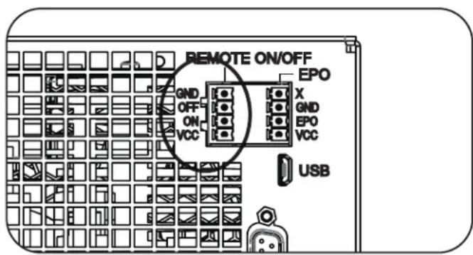
Remote ON/OFF Configuration
This feature is intended for switching the UPS to Bypass Mode for the Remote OFF configuration, or to Line Mode for the Remote ON configuration.
Note: The 4-pin terminal block supports wire gauges from 14-30 AWG with a strip length of 7mm . The M2 terminal screws should be tightened between 0.22 0.25Nm . Note: Before activating the Remote ON function, verify the AC input is present and valid.
Note: Before activating the Remote ON function, verify the AC input is present and valid. The 4-pin terminal block supports wire gauges from 14-30 AWG with a strip length of 7mm . The M2 terminal screws should be tightened between 0.22 0.25Nm

External Battery Connection
Check the Model Specific Accessories section under Overview for compatible battery packs and maximum quantities for your UPS system. Ensure that your battery pack matches the voltage listed next to your UPS battery connector. Adding external batteries will increase runtime as well as recharge time. See the battery pack owner's manual for complete installation and setup instructions. Make sure to attach the ground wire of the battery cable to the ground screw located near the DC connector first. Connect the DC connector and make sure it is fully inserted into its connectors prior to securing it with the thumbscrew. Small sparks may result during battery connection; this is normal. Do not connect or disconnect battery packs when the UPS is running on battery power.
IMPORTANT! In order for the runtime-remaining LCD and the software information screens to accurately predict runtime with external battery packs connected, you must configure via the Smart battery communication method (limit 4 Smart battery packs), via the front panel LCD or Tripp Lite's External Battery Configuration software. See Configuring External Battery Packs section under Operations.

When installing an external battery pack, observe all external battery warnings in the Important Safety Instructions section of this manual and follow the external battery pack installation instructions.
Troubleshooting and Event Log
See the chart below for explanation of UPS faults and warnings that can be accessed via the Event Log feature via the LCD screen or PowerAlert software, as well as suggested solutions for each fault/warning.
| LCD Display Message LCD Display Header Text Comments | ||
| UPS Internal Errors/Faults: | ||
| Inverter Over Current ** FAULT** If issue persists, contact Tripp Lite. | ||
| Inverter Over Current ** FAULT** If issue persists, contact Tripp Lite. | ||
| Inverter Abnormal OCP ** FAULT** If issue persists, contact Tripp Lite. | ||
| Inverter Bus Voltage ** FAULT** If issue persists, contact Tripp Lite. | ||
| Internal Comm Lost ** FAULT** If issue persists, contact Tripp Lite. | ||
| LCR Fault ** FAULT** The UPS will not turn on. If issue persists, contact Tripp Lite. | ||
| Transaction Timeout ** FAULT** If issue persists, contact Tripp Lite. | ||
| Emergency Shutdown ** FAULT** If issue persists, contact Tripp Lite. | ||
| RTOS Fault ** FAULT** If issue persists, contact Tripp Lite. | ||
| Low Power Supply ** FAULT** If issue persists, contact Tripp Lite. | ||
| Manual Bypass Fault ** FAULT** If issue persists, contact Tripp Lite. | ||
| PFC Precharge Fault ** FAULT** If issue persists, contact Tripp Lite. | ||
| PFC Over Voltage ** FAULT** If issue persists, contact Tripp Lite. | ||
| PFC Under Voltage ** FAULT** If issue persists, contact Tripp Lite. | ||
| PFC Over Voltage ** FAULT** If issue persists, contact Tripp Lite. | ||
| PFC Under Voltage ** FAULT** If issue persists, contact Tripp Lite. | ||
| PFC Over Current ** FAULT** If issue persists, contact Tripp Lite. | ||
| PFC Over Current ** FAULT** If issue persists, contact Tripp Lite. | ||
| Header Mismatch ** ERROR** If issue persists, contact Tripp Lite. | ||
| Fan Defective RPM Low | ** ERROR** If issue persists, contact Tripp Lite. | |
| NVR Checksum Mismatch | ** ERROR** If issue persists, contact Tripp Lite. | |
| NVR Invalid | ** ERROR** If issue persists, contact Tripp Lite. | |
| RTC Oscillator Failed | ** ERROR** If issue persists, contact Tripp Lite. | |
| RTC Corrupt Data | ** ERROR** If issue persists, contact Tripp Lite. | |
| Logging Error | ** ERROR** If issue persists, contact Tripp Lite. | |
| EEPROM Write Error | ** ERROR** If issue persists, contact Tripp Lite. | |
| Fan Over Voltage | ** ERROR** If issue persists, contact Tripp Lite. | |
| Fan Not Functioning ** ERROR** If issue persists, contact Tripp Lite. | ||
| NVR Status Checksum | ** ERROR** If issue persists, contact Tripp Lite. | |
| Load Sharing | ** ERROR** If issue persists, contact Tripp Lite. | |
| Battery Health Failed | ** ERROR** If issue persists, contact Tripp Lite. | |
| Double Queued Event | ** ERROR** If issue persists, contact Tripp Lite. | |
| EEPROM Queue Overflow | ** ERROR** If issue persists, contact Tripp Lite. | |
| Load/Temperature Related Errors/Faults: | ||
| Over Temperature | ** FAULT** In this mode, most power circuits should be off, thus lowering the temperature. Once in Fault Bypass mode, if the temperature exceeds the overtemperature threshold for 5 minutes, the unit will go to latched idle. | |
| Overload | ** FAULT** The unit should automatically revert from fault bypass mode to ECO/Online (overload release) when the load is reduced to less than 95% consistently for 10 seconds. | |
Troubleshooting and Event Log
| LCD Display Message LCD Display Header Text Comments | ||
| Battery/Charger Related Errors/Faults: | ||
| Max Battery Voltage ** FAULT ** If issue persists, contact Tripp Lite. | ||
| Min Battery Voltage ** FAULT ** If issue persists, contact Tripp Lite. | ||
| Max Battery Current ** FAULT ** If issue persists, contact Tripp Lite. | ||
| Charger Under Voltage ** ERROR OR ** The charger is working, but charge voltage is too low. | ||
| Charger Over Voltage ** ERROR OR ** The charger is working, but charge voltage is too high. | ||
| Charger Over Current ** ERROR OR ** The charger is working, but charge current is too high. | ||
| Charger Under Current ** ERROR OR ** The charger is working, but charge current is too low. | ||
| Charger Hardware Error ** ERROR OR ** If issue persists, contact Tripp Lite. | ||
| No Battery ** ERROR ** If there is no battery, only ECO to on-line transfers will occur. | ||
| Battery Over Voltage ** ERROR OR ** If issue persists, contact Tripp Lite. | ||
| Replace Battery ** ERROR ** | ||
| Low Battery Voltage ** ALERT ** | ||
| Low Battery % Shutdown ** ALERT ** | ||
| On Battery Timed SD ** ALERT ** | ||
| OtherWarnings and Events: | ||
| Number of BP changed | ** ALERT ** | If this change is unexpected, check smart battery communications. |
| Emergency Power Off ** ALERT Check | EPO switch status and settings. | |
| Bypass PDM Detached | ** ALERT ** | |
| Energy Saving Shutdown | ** ALERT ** | |
| NonSmart Batt Age Alrt ** ALERT Non-Smart Battery may need replacement. | ||
| Int Batt Age Alert | ** ALERT ** | Internal battery may need replacement. |
| Ext Batt Age Alert | ** ALERT ** | External Smart Batt {S/N} may need replacement. |
Internal Battery Replacement

Battery Replacement Door: Under normal conditions, the original battery in your UPS will last several years. However, batteries are hot-swappable. Battery replacement should be performed only by qualified service personnel. Refer to "Battery Warnings" in the Safety section. If you require a replacement battery, you can find it at tripplite.com/support/battery/index.cfm. See the chart below to find the right replacement battery for your UPS system:
| UPS Model Replacement Battery Cartridge | |
| SU5KRT3UHV RBC58-3US | |
| SU5KRT3UHVP RBC58-3US | |
| SU5KRT3UX RBC58-3US | |
| SU5KRT3UG RBC58-3US | |
| SU5KRT3UHW RBC58-3US | |
| SU6KRT3UHV RBC58-3US | |
| SU6KRT3UHVP RBC58-3US | |
| SU6KRT3UX RBC58-3US | |
| SU6KRT3UG RBC58-3US | |
| SU6KRT3UHW RBC58-3US |
See the following diagrams for battery removal and installation procedures.
1 Remove the six front screws from the front bezel, then remove the bezel from the UPS. Hang the bezel on the available hook.

3 Open the battery door.
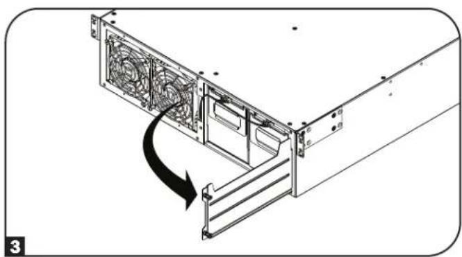
2 Loosen the two captive screws securing the battery door.
4 Using the handles attached to each tray, pull out the old battery trays slightly and disconnect the communication cables.
Internal Battery Replacement
5 Once the communication cables have been disconnected. Remove both old battery trays from the UPS.
6 When installing the new replacement batteries, make sure the red and black DC connector end is facing towards the rear of the UPS and the communication port is facing toward the front of the UPS. Starting with the right side replacement battery pack tray, insert the battery pack tray, making sure it protrudes slightly from the UPS. Repeat for the left replacement battery pack tray.
Note: For better connector access, attach the communication cable connectors before the battery packs are fully inserted into the UPS.
7 Reconnect the battery communication cables to the battery trays and push them completely into the UPS.
9 Reattach the front bezel to the UPS and secure with the screws removed in step 1.
6 Close the battery door and secure by tightening the captive screws.
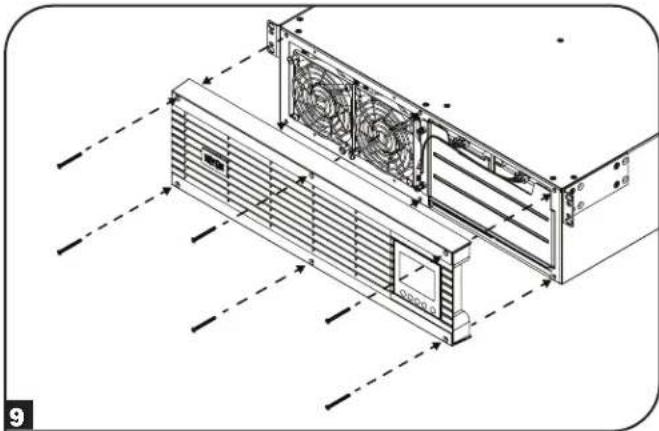
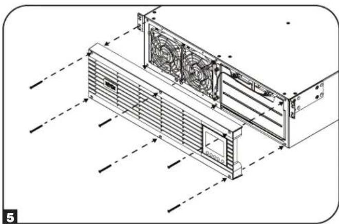
Fan Replacement
Under normal conditions, the original fan installation will last several years. The fan assemblies are replaceable. Replacements can be found at triplite.com/support.
CAUTION: The fan circuitry is not isolated from AC mains. Turn off power to the UPS prior to fan replacement. Fan replacement must be performed only by qualified electrical service personnel.
Before removing the fan assemblies, note the fan orientation. For proper installation and connectivity, the fans must remain in their original orientation.
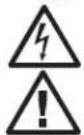
1 Remove the six front screws from the front bezel, then remove the bezel from the UPS. Hang the bezel on the available hook.
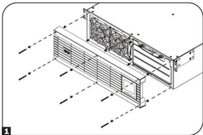
To replace the left-side fan or right-side fan, use a flat head screwdriver to remove the top-left screw and the bottom-right screw attached to each fan.
3 Disconnect the fan cable(s), located to the left of the fans.

4 Install the replacement fan(s). Connect the cable(s) in the same order as in step 3 and secure the fan(s) to the UPS in the same location and orientation as in step 2.
5 Reattach the front bezel to the UPS and secure with the screws removed in step 1.
Storage and Service
Storage
First turn your UPS OFF: press the "OFF" switch to turn power off at the UPS outlets, then disconnect the power cord from the wall outlet. Next, disconnect all equipment to avoid battery drain. If you plan on storing your UPS for an extended period of time, fully recharge the UPS batteries once every three months by plugging the UPS into a live AC outlet and letting the UPS charge for 4-6 hours. If you leave your UPS batteries discharged for an extended period of time, they may suffer permanent loss of capacity.
Service
Your Tripp Lite product is covered by the warranty described in this manual. A variety of Extended Warranty and On-Site Service Programs are also available from Tripp Lite. For more information on service, visit triplite.com/support. Before returning your product for service, follow these steps:
- Review the installation and operation procedures in this manual to ensure that the service problem does not originate from a misreading of the instructions.
- If the problem continues, do not contact or return the product to the dealer. Instead, visit tripplite.com/support.
- If the problem requires service, visit triplite.com/support and click the Product Returns link. From here you can request a Returned Material Authorization (RMA) number, which is required for service. This simple on-line form will ask for your unit's model and serial numbers, along with other general purchaser information. The RMA number, along with shipping instructions will be emailed to you. Any damages (direct, indirect, special or consequential) to the product incurred during shipment to Tripp Lite or an authorized Tripp Lite service center is not covered under warranty. Products shipped to Tripp Lite or an authorized Tripp Lite service center must have transportation charges prepaid. Mark the RMA number on the outside of the package. If the product is within its warranty period, enclose a copy of your sales receipt. Return the product for service using an insured carrier to the address given to you when you request the RMA.
Warranty and Product Registration
2-Year Limited Warranty
TRIPP LITE warrants its products including batteries to be free from defects in materials and workmanship for a period of two years from the date of initial purchase. After 90 days from the date of purchase, TRIPP LITE's obligation under this warranty is limited to replacing parts on such defective products. To obtain service under this warranty, you must call TRIPP LITE or an authorized TRIPP LITE service center. Products must be returned to TRIPP LITE or an authorized TRIPP LITE service center with transportation charges prepaid and must be accompanied by a brief description of the problem encountered and proof of date and place of purchase. This warranty does not apply to equipment which has been damaged by accident, negligence or misapplication or has been altered or modified in any way. This warranty applies only to the original purchaser who must have properly registered the product within 10 days of purchase.
The warranties of all TRIPP LITE surge suppressors are null and void if they have been connected to the output of any UPS system. The warranties of all TRIPP LITE UPS Systems are null and void if a surge suppressor has been connected to its output receptacles.
EXCEPT AS PROVIDED HEREIN, TRIPP LITE MAKES NO WARRANTYES, EXPRESS OR IMPLIED, INCLUDING WARRANTYES OF MERCHANTABILITY AND FITNESS FOR A PARTICULAR PURPOSE. Some states do not permit limitation or exclusion of implied warranties; therefore, the aforesaid limitation(s) or exclusion(s) may not apply to the purchaser.
EXCEPT AS PROVIDED ABOVE, IN NO EVENT WILL TRIPP LITE BE LIABLE FOR DIRECT, INDIRECT, SPECIAL, INCIDENTAL OR CONSEQUENTIAL DAMAGESARISING OUT OF THE USE OF THIS PRODUCT, EVEN IF ADVISED OF THE POSSIBILITY OF SUCH DAMAGE. Specifically, TRIPP LITE is not liable for any costs, such as lost profits or revenue, loss of equipment, loss of use of equipment, loss of software, loss of data, costs of substitutes, claims by third parties, or otherwise.
Product Registration
Visit tripplite.com/warranty today to register your new Tripp Lite product. You'll be automatically entered into a drawing for a chance to win a FREE Tripp Lite product!*
No purchase necessary. Void where prohibited. Some restrictions apply. See website for details.
Regulatory Compliance Identification Numbers:
For the purpose of regulatory compliance certifications and identification, your Tripp Lite product has been assigned a unique series number. The series number can be found on the product nameplate label, along with all required approval markings and information. When requesting compliance information for this product, always refer to the series number. The series number should not be confused with the marketing name or model number of the product.
Warranty and Product Registration
FCC Specifications for Models with FCC Class A Approval:
This device complies with part 15 of the FCC Rules. Operation is subject to the following two conditions: (1) This device may not cause harmful interference, and (2) this device must accept any interference received, including interference that may cause undesired operation.
Note: This equipment has been tested and found to comply with the limits for a Class A digital device, pursuant to part 15 of the FCC Rules. These limits are designed to provide reasonable protection against harmful interference when the equipment is operated in a commercial environment. This equipment generates, uses, and can radiate radio frequency energy and, if not installed and used in accordance with the instruction manual, may cause harmful interference to radio communications. Operation of this equipment in a residential area is likely to cause harmful interference in which case the user will be required to correct the interference at his own expense. The user must use shielded cables and connectors with this equipment. Any changes or modifications to this equipment not expressly approved by Tripp Lite could void the user's authority to operate this equipment.
EMC Specifications for Models with EMC Category C2 Approval (Select Models):
WARNING: This is a category C2 UPS product. In a residential environment, this product may cause radio interference, in which case the user may be required to take additional measures.
WEEE Compliance Information for Tripp Lite Customers and Recyclers (European Union)

Under the Waste Electrical and Electronic Equipment (WEEE) Directive and implementing regulations, when customers buy new electrical and electronic equipment from Tripp Lite they are entitled to:
- Send old equipment for recycling on a one-for-one, like-for-like basis (this varies depending on the country)
- Send the new equipment back for recycling when this ultimately becomes waste
FCC Part 68 Notice (United States Only)
If your Modem/Fax Protection causes harm to the telephone network, the telephone company may temporarily discontinue your service. If possible, they will notify you in advance. If advance notice isn't practical, you will be notified as soon as possible. You will be advised of your right to file a complaint with the FCC. Your telephone company may make changes in its facilities, equipment, operations or procedures that could affect the proper operation of your equipment. If it does, you will be given advance notice to give you an opportunity to maintain uninterrupted service. If you experience trouble with this equipment's Modem/Fax Protection, please visit tripplite.com/support for repair/warranty information. The telephone company may ask you to disconnect this equipment from the network until the problem has been corrected or you are sure the equipment is not malfunctioning. There are no repairs that can be made by the customer to the Modem/Fax Protection. This equipment may not be used on coin service provided by the telephone company. Connection to party lines is subject to state tariffs. (Contact your state public utility commission or corporation commission for information.)
UPS and Battery Recycling

Pb
Please recycle Tripp Lite Products. The batteries used in Tripp Lite products are sealed Lead-Acid batteries. These batteries are highly recyclable. Please refer to your local codes for disposal requirements.
You can call Tripp Lite for recycling info at +1.773.869.1234.
You can go the Tripp Lite Website for up-to-date information on recycling the batteries or any Tripp Lite product.
Please follow this link: tripplite.com/en/support/recycling-program.cfm
Tripp Lite has a policy of continuous improvement. Specifications are subject to change without notice. Photos and illustrations may differ slightly from actual products.


Manufacturing Excellence
1111 W. 35th Street, Chicago, IL 60609 USA · triplite.com/support
1111 W. 35th Street, Chicago, IL 60609 USA • triplite.com/support
PykoBODCTBO NOIb30BaTeJIa
SmartOnline
Ondhoa3hbi CtoeHbI OHnaH-NbPi
co BCTpoehhbIM XXK-3KpaHOM dIy KOHTpOJI ynpaBHeHnA
He npedna3aHaeNo nIpepeBnKHO TexHNKn.
Moden:
SU5KRT3UHV, SU5KRT3UHVP, SU5KRT3UX, SU5KRT3UG, SU5KRT3UHW, SU6KRT3UHV, SU6KRT3UHVP, SU6KRT3UX, SU6KRT3UG, SU6KRT3UHW
(Homep cepnn: AG-0358)
- Kpatkoe onncanne 104
KoMnIeKTeaun 104
DononHnTeBhBle KOMnEeKtyoune 104
-
Baxhblte yka3aHHNo ToTexHKe 6e0nacHocTH 104
-
3neKtpueckar6nok-cxemaHb107
-
yctahOBka 108
Nobopor BHYtpenHHx 6aTapei 108
MOHTAX B CTOIKy 110
BepTKaJIbHbI MOHTaK 111
Keckni Ka6enbHbI BBOI N BBIOI 112
Yka3aHnno MoNTaHy 3JeKtpnpoBODKn 113
(JnOaTDeBbIXMoJeIeOnuHOHaNbHO)
BxOu BbXoH N5Pi: 06uee onncannne
Bapnhtb Bblbopa peXHMOB nHTAHN 121
Bapnhtb Bblbopa H KOnHpyaun 123
CnnoB3OBAHmE K-K-dncnneHa nepeDne HnaHn IVbI
HactpoKa BheuHero 6noka aKymyIaTOpbIx 6aTapei 126
-
Pa3bembl IINIOKNIQUeHnOuHOHaJIbHbIX 3neMeHTOB 127
-
BbIaBHeHne N yctpaHeHne HeNcnpaBHOCTe HxypHa 130 co6bITn
-
3aMeHa BnYtpEHnX 6aTapei 132
-
3aMeHa BeHTnJIaTOpOB 134
-
XpaenHe N TeXnueckoe 6cbnykBaHne 135
-
TapaHTHbIe 063aTeJIbCTBa 135
English 1
Espanol 35
Francais 69
PIMMEAHHE. BHeHHe 6KKn AKKMyIaTOpbX 6aTepe Tpe6yOT HAcToe KcNOnb3oBaHMe KK-HnTepeCnepeHne naneHn npn noMoAnpnpnaem
TrippLite nporpammmoro o6ecneueHHA HACTPOKNI BHEUHIX BATAPEI.
EAC


PpOpyuHmBauoTcE KHPKCT88
1111 W. 35th Street, Chicago, IL 60609 USA - triplite.com/support
OxpaHaeTcA ABTOCPKMM npabOM 2021 Tripp Lite. NepeneuataK3anpeuaetc. SmartOnine ABAeTcTROPBbM 3aKOM KOMNAMHI Tripp Lite.
Ia nolnyeHnnaNoceDnHex OXOBHbEnHn pnrnaAeMaB aocneTb Hau caT triplite.com
Kpatkoe onncaHne
CtoeHbIe IBII Tripp lte SntOnline c HtepakTHBbM KKHHTEPcHOM oecneuMaot 3aunty B pekHMe OHnA H CBOHbIM poe6pa0BaHmmpn HnpepeBHOIOndepKBe bXoHOro hnapaehn CHyTcHcyom dNabHOH fopMbHy HnyeBOrO BPemEH nepeKIOUeHN, UTo obycnaBnBAET IN npriFOHOCTd PAcWpHeHHx PnKlAaHbX 3aauB CetEBbx IHpPacTykpyax. KaKdbI I5Ib OecneuBaet dIITENbHyO paOByOT bApatec B O3MOXHOCTAMN IpODAHNEBA BPEMeH ABTOHMHO paObToH CB3aYpe3 Be6-HtEPcEcbi. BCTPOeHbIE MHTpeFcBc: Micro USB, RS-232 (noceobbaet bHbH) EPO (abapAHOn OTKIOUeHN NITAHNA), ROO (INCTAHIOHOHE BKNIOUeHN/OTKIOUeHN) nOpT RJ-11 DnOgKIOUeHNs BApae Tnna "smart". HtepakTHBbH NK3KpaH nepedH naHenn oecneuBaet oTo6paKeHne NOpOboHn HfOpmaun O CTatye IBI, A TAKKE Bo3MOXHOCT ppeBapTeHBHO YctAHOBKn napametpoB n HaCPoRnE MeEMTOB YnpaBHeH NDOJONIHENTbHe BO3MOXHOCT DoTOKHeHN MaKcMAmalbHorO KII AND ATOmatueckOHaCTpoRn PEKMMOB NtAHA HNObEcoN HeBHy POaBoTy cNoNHKeHHbIM Notpe6JeHem MoUHcOIn TEnNOBbDeneHMe.
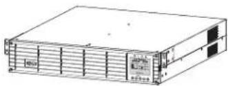
KoMnIeKtaun
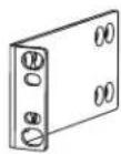
MnMOHTaXHbI npOuHHbI c6oJIbOBIM
KpennneHnem (2 wT.)
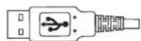

USB-ka6enb(1wT.) Ka6enb RS-232 (1 wT.) [Дя от dembHx moDEe]

KOMNNEKT HANpABNIOUX DnMONTAXA BDbYXPAMHYO CTOKy
KOMNEHCATOpbHaTaeKeHJXeCTKOrO KaebbHoro BbOda(2Wt.)
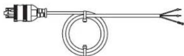
BxOHOH WHPNITAHNA NEPEMEHORTO TOKa cp3bEMOM L6-30P (1 wt.)
PykoBOCTBO NoIb3OBATeJIa
OnuHaHbHbIe KOMnEeKTyOuHne (B KOMnEeKT NoCTaBKn He BXoAaT)
-2POSTRMKITWM: KOMPNEKT OCHACTKN DPN MOHTaKa CTOeHORO W5II N 6IIOKOB AKKymnTApbix BaTapeB O NDhopamHyo CTOnky nHa CTEny
2-9USTAND:KOMNIIeK T OCHaCTKN DRA BepTnKaIbHOro MOHTaKa CToeHOrO N5Pi N 6NoKOB AKKyMylATOpHBx 6Taapei
BHeuHm6nK AkymyIaTOpbIX 6aTapei Tna SMART" MoD. BP192V12RT3US: o6eueuMaET npOJIeHne BpEmHn ABOTHOMHO pa6oTB H5P

XHbIe yKa3aHnNo TeXHnke 6e3onacHocTm
COXPAHNTHE HACTOUIE YKA3AHNA
B HactoIeM pykoOIOCTBe cOepKATBaKHe ly yka3AHn I npDeynpExdHn, KOtOpbI Heo6xOJMoCo6HnDaT B npocece yctahOBKn, 3KcIpyaTaun, TeXHueckoro o6cyjNBAHN I xpaHEnBex IVII AnkymyAToPbIX 6bATEm MapKn Tripp Lite. mHrhopnoBaHme 3TNx npdynpExdHm MoKeT npBectn K notepe rapaHTn.
YcIOBhIe 06O3HaueHn

BHHMaHHe - onaCHOctb!
BbICOKaTEmpepa-Bo3MOKeHnepepeB
Oanchoctb npaKeHnE nekTpueckm TOKOM
3aumthoe 3aemneHnE


3a3eMJIeHcCypaHBnBaHHeMeIToTeHmAnoB

Pb
PnroDHO DnNEpepa60TK CooepKHT CBHeHc
IpeynpexdeHnOTHoCteNoMeTa pa3MeeHnNb
- DaaHbM 6B1 npdeHa3aHcHnI HcNtB30BaHm B 3akpbltx NOMEeHmC perynpmyoem TepepaTpyo n 0THOCHTbHO HmKIM COepkAHMe 3NEKTPnpBOHBx 3aRpa3HNTeY. YCTaHbHBAITe WBI 3aKpbTOM NOMEUHMn BdAnI OT NcTOHKNOB 36bToOHN BnA rnnn TnIe, 3NEKTPnpOBOHBx 3aRa3HNTeN, nbIn n pPAMrO cJIHeuHOr CBeta.
TeMnepaTpyaOkpkaHooIero Bo3Dyxa BIOmeuHIMdoJNkHaNoJIePknBaTcBcB DaIana3OHe o 0 do 40^
CoBCEsCTOPOHINIeNoE6xDmIOMo oBeceNtBuTOAtoTuHO CBO6OJHOro npoCTpAnCTBa IraeroHaJIeKaUeeroPiobETrnBaHnA. - ⅥПОСАЦЕн HeCк�КИМУ yD6bIMn pOeTkaMn, H0 B pexime pa6o7bI no 06xOДHoi ZENH HE o6ecneuBaet 3aHTy NpOKNIOUeHOrO o6bpOyBaHmY O T bI6pocBnHaPRAeHnry nIyHMn.
He MoHTpyuye yctpoCTBO c3a6oKnPOBaHNOpeJeHn Hm 3aDneHn aeHbIy. UcTahOBKa IVIIOO6bHm O6pa30 nPMBeT K co3dAnIO cepE3hXn npTeATCTBn dIra CHTeMbl BHytpenHe BHTNIAUH yctpoCTBA u, B KOHeYHom ITORe, K NOpeKJeHNO IVI, Ha KoTope He paCpOcTaPAHOTcRapAHmHbYe YcONBIA.
IpeynpexkdeHn OTHoCtEnbHO yctaHOBNIOKNIoueHn N5N
Bce moen

BHHMAHNE! Uctanovka doJnKHa npOIm3BoDnltbca TToIbKO KBAIMHmUmpoBaHbIM cepBnchblm nepcoHaON mEneKtpoTeHNueCko npOma
YCTaHOBKY CnEpyT npOHN3BOINb B COOTBETCTBmC Tpe6oBAHMAH MauHNOHaBHyix 3eKpTOTeXMHueCKHX HOpMaTHOB. O63aTeNbHO NcNtBcyTe nDxOJaune Iy YCTaHABNAEMO CHCTMBI yCTpoiCTBa 3aHTbOt NT pepepy3OK n TOky B COOTBETCTBmC HOMHHaAAMy, yKa3AHbIMM Ha pa3bEmax/06OpyDobAHM.
063aTeBHo IcNOnb3yIte BocXoJaIHHABOTOMaTHueCKMHbKIOHcTebC KpHBOI OTKIOUeHnMa TnA C.
3aHToTnepepy30KIO TOKydoJXHa o6eCneYBaBcB CmCTeMe, PpeHaa3HaueHHo Ira KOHeuHO rno b3OBeTEn, YCTaHOBKa KOTopoI DoJxHa 6bItpnp3BeEHa B COOTBeCTBMn C MeCThBIMN 60eHauHbHIMn pabnAmn 3eKeTPOMOHTaKa.
- Pn mo nontae 3neKtpoipobOdk B 3daHm, npdeonanaIoueem IcnoIb3oBaHme KOHpyaum C JceTKM KabeHbHIM IOIDKIOueHM, DIOJHO npEDyCMtpBaTbC HAIUMe pe3epBHO 3aunTb ot KopOTko 3ambkaHm 3aunTb OTpeppy3ok no ToK (DnpekMa pabotb no 06xoHdH eH N EKOHOHMHOr opeMMA).
YctahOBKa DOnJXHa NpOu3BODnTbCn Ha BbcOTe He 6onee 1M.
- 06OpynBaHMe npEHa3NaUeHOnIaNcNoB3OBaHmBA B CSteMe paCnpeJeHnHn NtTAnHc 3a3emHeMm TnTa TN-S.
OTdJIbHbIe MoDJIH OCHaIauTcI WTeNCEJIbHbIM pa3beMOM Tnla L6-30P

BHUMAHNE!IyHnKHeHnPcKaB0rOpAHnCneJyT PnO3B0DnHTb NpO3NIOUHeHnTOBko K KOHTpy, OCHaENHOMy 3aIHTOn OT NepeRpy3oK No ToKy Do 30 A C nOJIb3OBaHMe IuyTHIpOuSeIeNi,Knacc KOTopoI DOnKe HcoBTcTBoBaTb Tpe6oHaHnHnHaUHOHbHoro CBODa 3aKOHOB n CTAndaptob CIJA no 3NeKtpotexHnke (NEC) (ANSI/NFPA 70) n KaHAdckoro CbOda 3aKOHOB n CTAndaptob IO 3NeKtpotexHnke, Uactb I, C22.1.
CetbeWttenCeIbHpa3bemL6-30PcIyHHTBkaueCTBeYcTPOCTBA3aunTHOrOOTKIOUeHHe.3neKtpuueckHePO3eTKH,Hepe3KOTOpBEOCyUeCTBnTeTc3NeKtpoNTaHHeOBopyoBaHn,DJIKNb6bItb yCTAHOBnHbBnKOoCTyHOMMeTe BnHnHrEHO.BnPTOBHOMcIyaeMoKETNCNlOB3OBaBCaIokalbHoeYcTPOCTBOaunTHOrOOTKIOUeHHe.
- Pn HauHmH uTencBhoRo pa3bema L6-30P HE CIEyET HcnoB3oBaT JkeCTKn Ka6eBHy BBOd NepemHeHO TOKa. 3To MoKet npmbctn K Bo3NkHObeHNO kataCtpoFneckn onaChOn ChTuayuMn
Ipn HcNpIb30BaHmJXeCTKOro KaebIbHOrB BbIOda NepeMeHHoro ToKa HeO6xoIMMo oEcePHTb HaDnEkaaHy 3aUHTy O Tnepepy30k NBObxOHOmy TOky.
IaonTaeNbBx MoDene CKeCTKIM Ka6eBbHbIM NoKnIOueHem

BHUMAHWEI INCHIKHIM PIMCA B03ropAHN CNEyET IPOIN3BOIDITB NIOHNIOHENe T0Bko K KOHTpy, OCHAENHOMy 3aHTOIT OT NIpeRpy3oK NO TKO 30 A cNIOb3OBAHEM WHTIPYooie ZeiN, KNaCC KOTopoIN DQNHE COOTBCTBOBaTb Tpe6OBAHnM HauioHAnbHorO CBOda 3aOKOH IN CTANdPTOB CUSA NO 3eKTPoTeHXKe (NEC) (ANSI/NFPA 70) IN KaHAcKOrO CBoDA 3aKOHIN CTANdPTOB NO 3eKTPoTeHXKe, Yactb I, C22.1. Boone NoPpO6Hn HNOFPOMaHn PpeCTabHe H TabHe "BxOIN BxOIN 5B1: o6Uee OInCaHne" pa3Dena YctahOBka.
MnIb3yIe TOnbKO MeDHyIO npOBdky C npOBdAMn, paccuHaHHbIM Ha TemnepaTypo 105°C. PekomeHdyemar KOHpyraaBxOIOB N BbIXoOB npedctabHeA B TaJIme "BxoN M BixOJ NSI: o6iee onCaHHe" pa3dena YCTAHOBka.
I Moeen, OCHaHHeBx JcKTHM KabeBbHM BbBOOM, B yCTAHOBKe Ie KOHeHOrO HcNoB3oBAHm DIOJHkO oEcbneuBaTc 3aunrO t Nepepy30K n Toky. NcnoB3yIte 3aunrO t Nepepy30K n BixOHMy TOky HOMHaON, He pBeBlaAoum BxOHOH HOMHaN bI. Pn yTaHOBke PO3eTOC 3aunrO t Nepepy30K n TOky c BoJe e Hn3KM HOMHaON HOMHaN 3aunrO t Nepepy30K n TOky dOnjhen COOTBETCTBOBAt HOMHaNly PO3eTOK.
B CtpaHax EbpnoI abTOMaTcckn BbKIOUaTeN bOJKeH COOTBeCTBOBaTa Tpe6oBAHm CTaHApTa IEC/EN 60934 N MmTe TbOzdyuHbI 3aOp MeJy KOHTAKTAm He MeHee 3 MM.
I pH nIOJIb3OBAHH JXeCKTko Ka6eJIbHO BbIOa nepeMeHHOro ToKa yCTaHOUBuK 063aH o6ecneHTb HADJIeKAUy 3auNTy ot IPEEPY3OK TIO BbIXOJHOMY TOKY. Heo6xoIMMo HcNtB3OaTb ABOTMATMueCKHe BkIIouateH C HOMHaON, COOTBeCTByUoMM HOMHaNany 3auuMaEBx PO3eTK / 3nEMeHOB 6OpdyOBaHm. NcIOnb3yIte ABOtMAUeCKn(-) BbIKNuOATEb(-) c KpINBOI OKJIIOUeHMA TnA C.
CtaunHapna 3eKToPpOboDa doknHa Hmetb IerKOoCTynHO BcTPOHeHcYcTPOcHTBO OTKIOUeHn DByxNIOIOCHOrTO TmTa CcoOTBeCTByOuIMn npaMometpMa.
BCTPAAH EBOPTI pa3bEM pINKIIIOUeHIM K cTNI IpeMeHHORO TOKA HMEET KOHTAOKTBI L, N, PE(3EMIA).Y6eINTEcB TOM, YTO KOHTAKT L PNOIKIOUeH K aO3OBOMy npoBOdy, a KOHTAKN — KHyNEBOMy npoBOdy.
HnB KoeM Cnyae He npOn3BODInTe MoHTaK 3IeKnTPOo6OpOyOBaHn B0BpeMa rpo3bl.
- He mCnoIb3yTe daHnOe 6obpyoDaBHMe B cnyae noBpeXdHMe IIO6oM I3 erO qaTcEi.
ToK, nOtpbeAembmy ot dIeBbIMn 3IeMeHtAMn o6OpDyOBAHN, noDknIOaembIMn K WbI, ne DOnKeH npeBbIaTb HOMNHAL COOTBETCTBYOUXx po3eTOK.
CymmaHaray3ka OITnope6ntene, noKJIOHoueHNbIX K IVI, He doJIKNHa npeBbUaTb erO MaKcUMaJIbHO DoNcyTmHyo Harpy3Ky.
- He BHCNTe H3MeHEnB KOnCTpyKUIO IVI, ero KOpnyca, BxOxDhIx pa3bEmOB INN Ka6BeJe nnTtHa.
He mncnlo3yIte WbI Bcnyae noBpeJedHna IIO6o H3 erO cuaTeH.

Baxhblc yka3aHnno ToTexHnke 6e3onacchoctn
PpeynpeKdEHHN oTHocuTeNbHO nokKnOueHn 06OpydoBaHn
He npKIOUaHte cTeBbIe pINbtpbI uN Ka6enu-ydmHnTENu K BbXOyD IV5P. 3To moKeT npBaBeCTN K nolomke WbI c notepe r IpaAHTM K aK h a cTeBcB O mIbTp, TaK H N HA IV5P.
CymmaHarHarpy3KaOTnOtepeTenei, noKJIIOueHHbIX K N5II, He OJnxHa pBeBbIaT b erO MaKcMaJIbHO DoynCTMHyO Harpy3Ky, yKa3aHHyO Ha 3aBOckOa Tabmne.
He peKoMeHdyetca HcNoB3OBaHMe daHoro obOpyObaHn B CNTeMax KJ3He06ceueHn, Ige erO bIxO n3CPOr npEpoNIOKtEnbHO MoKET npMBeCTN Knepe6oAMBaP6ote 06pOyObaHn Jn3He06ceueHn nn B 3auTeJIbHo Mepe Chn3ntb erO be3oNaCHocT bnn 3fKeKTHBOCTb. He MCNoB3yTe daHnoe O6pOyObaHn B cpeax, o6orauenbIX KcnOpOdom, a takaKe B padNyce 0,3 m Ot Kaoi-Ni6o TouKn, Ige ocUeCTbAeTc pinnHyDInTeHbHn OTbO TaKoi O6oraueHHo KcnOpOdom cpebl.
IpeDynpexKeHne no 3aMeHe BENTnIaTOpOB

Ipeel 3aemen BENTnTApOB y6eHntecb TOM, YTO IV5Pi o6ctOey (BbIKIOueH). HeBbINONHeHne daHHoro Tpe6oBaHm MOxET Bb3BaT b neperpeB H 3aunTHoe OTKIOUeyHne.

BHUMAHNE! 3neKtpueckcaeBnNTaHnBEHTNtTopOB He 3OtnpObHa OTe Cte NepemehHOro ToKa. Ipeed 3aMeHOB BENTNtOpOB BkHIOHTe NTaHHe IVI. 3aMeHa BHTNlTOpOB DoJXHa POn3BOuTc KaBAnHmPunOBAHHbIM CepBNCbIM EpcoHAlOM 3NeKTPOTEXHueCkoRTO npOHN.

IpeDynpexkdeHnOTHocTeJbNo 6aTapei
BHytpn IBHn HET dTeanen, 06cnykBaembIX NOnb3ObaTeJeM.
-Поворот батей доженnpиювдьтбя КВалфишировангьм серсьнчылп epcoharolл ЗелктохучecКО рpoшILA.
3aMeHa 6aTapei DoJIHnIPOIN3BOIDITbCra TOnJIbKO aBTOPNI3OBAHbIM cEpBNCHbIM NepCOHaNOM.
TexHueckoe 06cnyKBAHHe 6aTapei dJxHO OcyIeCTBJIbTcR INN KOHTpOINPOBaTbC rCeIaIInCTAMN,3HaKOMbIMn C I X KOHCTpyKUne N pINHmNOM paOToI, a TAKKe Heo6xoMIMM MepaMn npEOCTOpOKHOCTN.
-ПиЗЗаме6БатарспсдуETУСТАВИВaВТББатарсИМN6БOKN6БатарсTOrTOжТИнВВTomжKOJIИЧЕТBE.
BHIMAHHE! He 6pocaiTe 6aTapeB OOrHb. BaTapeN ABnIOTc B3bpBOOnaChbIM.
BHIMAHHE! He BcKpbBaIte KOpnyca 6aTaapeH n H e DonycKaIe Mx NOBpeJeHnA. BbInneChyTb HApNyJ 3NeKtpOnl OanCen IaONKoM nHa3. KpOme TOrO, OH MoKET ABNATBC TOKCNHBM.
BHIMAHME! 6aTapeMOKETBIAIBCTCAHOTUHMKOM ONaCHOTN IopAaeHHN 3eKTPueckm TOKOM KopoTKOra 3aMbKAHA. PnIKCOHEHeK JIOooh YactH 3aemHeHOB 6aTapeMooKET npBeCtN KnpaKeHHNO 3eKTPueckm TOKOM. Pp np a6ote c 6aTapeAMn Heo6xOIMO CO6bIeHne CneDyOuHX Mep PnpocToPOXHOCTN:
- Ipepe npabotoi CHMNTe C c6bHaHpyhIbe YacbI, KOBIua N dpyrme MeTaNJIueCKe IpeMeTbI.
IcnoIb3yIte HnCTpyMeHTbI cN3OIpOBaHHbIMpyKaAM. - HandeBaItepe3nHObIe nepaTkn 06yb.
- He KnaDte HnCTpymTeBtI Nm MetaIIuueCKme DeTaN Ha BepxHMe NOBepxHocTn 6atape.
3anpeaetc3ambkaTbnnncoeHHATbKJIeMMbl6TaapeCnONb3OBAHMeKaKOro-nI60npEMeTa. - YctpaHnIte 3a3emHe H6atapEn Ha BpeM ee yCTAHOBKN I TexMHueCKTOO 06cnyKbAHN C cenbIO CHINKHeHBEPOrTHoN paoKHeHNEAekTpueckm TOKOM.
- EcnI KakaJ-Ni6o Detanb 6aTapen 3a3emHea, yCTpaHnTe ee KOHTAKT c3emNe.

IpeynpexdiennoTHocntelbHO BHeuHx6aTapei
Ipepe npoknoueHneM BHeWHei 6aTapeK NbPi npocoeHHte K He 3aemnoi npoBOd.
-Информаши по Habстриke Вс�шимбатарe(BapnaHTb KoHpIpyaunm n cno6 hactpoikn)прдctabneHaВ pa3dene "Kcnpnyataua".NПpacno3haet 6nOKu AkkymyTOpHBx 6atapeTtna"smart"abTomatUcheKn.
3aMeHa npEdoxpaHnteJe DoJHKHa npOo3BOHbCra TOnbKO yNoHOMOueHHbIMn CneuaHnCTaMn npEepnpyTn-13rTOBmTeJI. CMeHHbIe npEdoxpaHnteJe DoJHKbI HmEtB TO TKe TnH HOMHNaI.
I py npdoJIeHMA BpeMeHn ABOTHOMHOI pa60tBu HcNOb3yTe ToJIbKO CoBmCTMble 6IoKo 6aTapei Tripp Lite:
BHeuHmI 6nok akkymyIaTOpHBx 6aTaepe BP192V12RT3US

Baxhblye yka3aHnno TeXHMke 6e3oNaCHOCTN
3aMeHa u TtUIn3aun6aTapei

Pb
Bn3dnnax Tripp IHCN0b3yOToC repMeTNUHbceCBNtOBO-KNCnOThbE batape, nprrOnhbeIra ny6oKOBHTOpMHo nepepaotKn. Tpe6obAHmno yTNImaun onpeDnHOTcMecTHbIMn HopMaMM n pabuNaAMn. DnI noJyEnHn 60nee noJnp6bOH mHOFpaMQUN o BTOpHNOH nepebaotKe batae mNIOb6x dpyrX n3denM MapKu Tripp Lite obaauiTeCb B KOMNAHIO Tripp Lte No Teneohoy 773.869.1234 nn NocetHe Be6-ctpaHuy triplitte.com/support/recycling-program.
AccoPHTMEnT Tripp Lite BKnOuaeT Be68 CmHbIe 6aTepeHbIe KaPTpNkInnBex MoEneu IV5I.
Tne Tte Be6-ctpaHnu Tripp Lite no aepcy tripplite.com/products/battery-finder/, rde BBc moKTe nOdo6pTa CBmHHy 6batapeIO dBaue Moen I5I.
IpeynpexdeHnOTHocTeNbHO TexnueeKOro 6cbnykBaHn
BHytpMbHETdTeaney,06cnykBaembIXnlo3oBeTeneMe.He pa36upaiyeycpoiCTBO.
3NeKtpnuecka 6NOK- cxema IV5N

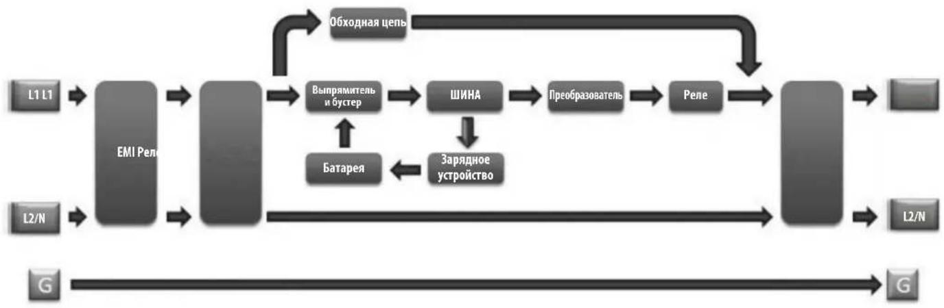
YCTaHOBka
NobopoBt BHyTpEHnX 6aTapei
IbDnHNO MoEN NoCTABNIEcTc OcoeHNHeHHBM 6bATEAeMn, paONaRauuMMnCBA 6bPAHOI opNEtuaM. IpeE moHTaKOM IBB DByxpaMHyIO INN ODHOPAMHyO CTOKY BbHbTe 6bATaeHbte OTEcKINOTXKeHMe INB CTOPOHy. IN3BNEeHMA6bATEH N5IB BYINHInTE H3NOKeHHe HINKHEHCTpykUIM.

Ecn npednonaraetc nnonb3obAHne BheuHrno 6noka aKKymyIaTOpbix 6atape, TO OH dONKe H 6bTb YCTaHOBHe NEPbIM B HHXHE cHTN K. IpexKe yem nepeiTu K yctahOBke H5Pi, Heo6xOIMO BblIOINHTb yka3aHn, hIOKeHHbte B NOpa3dJe HAcToPka BHeuHIX 6nOKOB 6atape HactoJero pykoBOCTBa u PykoBOCTBa noh30BaTeNa BHeuHrro 6noka aKKymyIaTOpbix 6atape MoD. BP192V12RT3US.

BHUMAHNE! Nobopot 6atapei Donjhen npo3bOuTbc KaBnHnnpoBaHbIM cepBnCHbIM nepcoHaON 3eKtpoTeXnueckoro npoHna.
1BbIeHPHTe WeCTb NepeDnHX BHTOB IV3 NIIeEBO nnHEn H5N BbIHbTe ee HapJyK. POBecBe TneHJIb HA IMeOuMci DnA ETOK
PnmeHne. nncnnn ha nepedne naen nnoocnne nepe3 nehtouhkb kaebn, npnooxehnh ot Nk nueeboananei. 3T0t Kaebne He nojckn npnratctBOBATb OKpbBAHIO n 3akpbBaHNO DEpbr sbatapennbIX OTEcOB;cTOnmBoMOKHOOTcoeMHHTb DnCnne ot nnebo anen c TOMOoi bO TOBPTK.
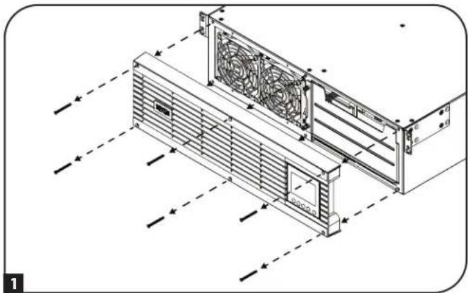
0cna6bTe Dba HeBbinaDaaIOx BnHTa, oecneuBaIOx KpenneHne Ibpui 6aTapeHHbIX OTceKOB.
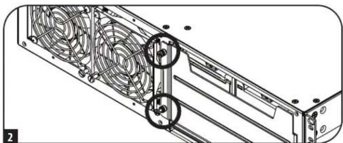
0TOKpoIte DBepy 6aTepeHbIX OTEcKOB. KOMMyHNkaIOHOHHk Ka6eBb Smart Battery He DOJXHE NpEYATCTBOBaTb OKpbBaHIO DEpeBb 6aTepeHbIX OTEcKOB HIX H3BNEeHIO.
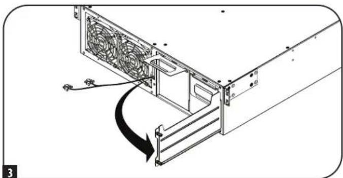
BbHbTe 6aTapeHbIe OTEcKn 3a npHKpeHHbIe K KaKIOMy N HxpyKn.IpeN BpaueHMe 6aTapei (CM. CneJyouuiu War) Heo6XoIMMo CHrTb pyKN H yCTaHOBNtB Mx C npOTBOIOnIOXHOI CTOpHbI.
PnmeHne. JyMCHBxHMeMaCbI 6B I npOeCE yCTAHOBK peKOMHeYcTBAIOHNHTy kA3AHNo moTAnKy B DByxpAMHyIO INN ODHOPAMHy CToKy, NIOKeHHe B pa3Dene MoTAK B CTOKy, nepe BpaSeHEm, NOBTOHO YCTAHOBK IONDKNUeHEm 6aTepeHbIX oTEcKB.

YCTaHOBka
KaKbIb 6aTapeHbI OTEc MEET pAIIbI-pa3Bem NOCTOAHHO TOKa. PaCNOJOKte Bce 6aTapeHbIbe OTEcKn TAKM O6pa3OM, YTO6bl COeIMHTeJIbHbIe KNEEMMbI NITAHmnoCTOARHHORo TOKA KpACHORIO UePHORIO CBETOB 6bln MOpaeHbIK TblbHcN CTOpOHe 15P, a KOMMYHkauOHbI NoPT - K INeBOE CTOpOHe 15P. BCTABNHE 6aTapeHbIE OTCEKn, HauHna C npArBOr, TAKM O6pa3OM, YTO6bl IX KOPyCa HEmHO RblabANCb 3a npdeHbI KOpNyCa 15P. IobTopTe Te Xe DeIcTBn DnIg 6aTapeHHO rOteCa c NeBoi CTOpObI.
PnmeaHne. Jna oBnreHnnoDcTyna K NkEmMaM nooCoeHHnRE Ka6eN K 6bapeHbIM 6nokmdoToTO, kAK OH6yDyNTnoHOCTbO BCTABHeNBbKopnyc WfI.
6IIOaEOHInHTe KOMMyHKaUMHOHHb Ka6eb 6aTapeN K KaXdOmy 6aTapeHOMy OTcEky M BdBnHbTe 6aTapeHbte OCEKn B Kopnyc IVp Do ynopa.
73akpoTe DBepy 6aTapeHbIx OTeKOB 3AkpenIte ee, 3aTaNyB HeBbIaDaIoume BINThb.
8 PncoeHnHTe HnueByo naenb 6opatho K N5N 3akpenite ee c nmoBBO BnHTOB, BBBePhyTbIX Ha Ware 1.
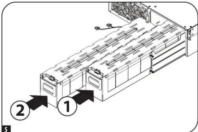
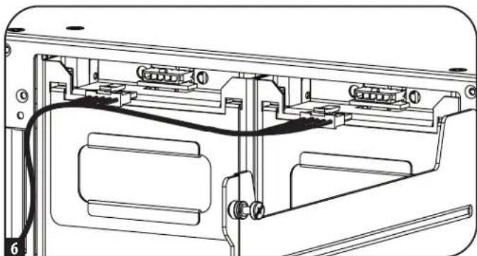
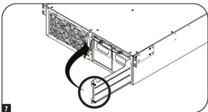
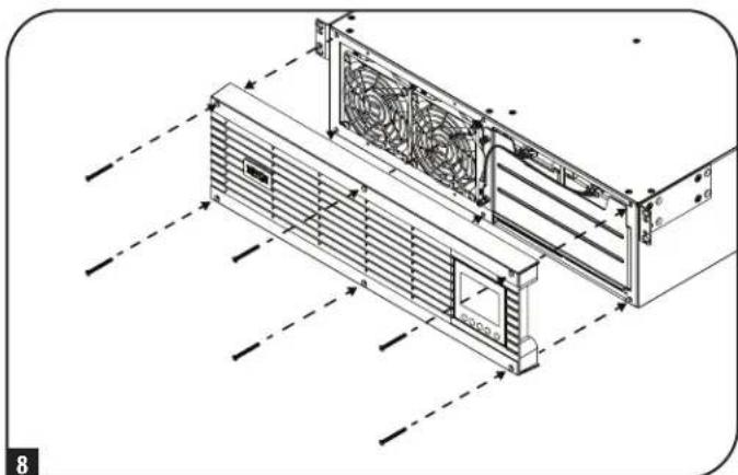
YCTaHOBka
MOnTaX B CToiKy
YcTaHOBKa 0bOpDyBaHnOJNkHa npOn3BODHTCB B OndopAmHbE Hn DByXpAMHbE CToKn NIO6UkaΦb. POnb3OBaTeNb DOnKeH yCTaHOBnTb nPrrOHOCTb OCHAcTHN nPpeIOnaRaEmbIX npOeDpy Do hauana MoTtaka. Ecn OChACrKa N ppoeDpyb He COoTBcTcBYOT YcOBnAM NcNoB3OBAHn OBOPyOBaHH, CBAAHTEc b POn3BOIDTeMe CBoe CToKN MIn CToeHOrO ShKaΦa. OncAHhBe B HactoJeem pykoBODCTBe npOeDpyb PrPeDaHa3NaHeHb DnA obHyBx TmOB uKaΦoB N Moryt He NoxDxOHTb DnB CEx cene npImHeHHe.
BHIMAHHE! DaHnoe 6obOpDobAHne DOnKHO yCTaHaBnBaTcH a CToeHbIe HAnpaBnIOUHe Ha BbICote Do 1 M.

Ecn npnnonaraetc hncnb3obahne Bhehero 6noka akkymnyatopbix 6atapei, to OH donken 6b1b yctahOBnepnBm HnHexnactnckn. npekde qem peeyntu K yctahOBke 65n, heo6xmoMb bblnoHHTb yka3aHn, n0xKeHHbte HocpKa BHeuHnx 6okob 6atapeHactoJero pykoBOCTBa HpykoBDCTBa noIb3oBateTna Bhehero 6noka akkymnyatopbix 6atapei moj. BP192V12RT3US.
MOHTAX B DByxpaMHyo CToiKy
1 NoctabnBmBb B Komnneke TnAaTmacCOBbIe WntHbI A o6ceNayt BpeMeHHyO onopy dna HeHarpyKeHHbx CToeHHbx NOK Hb BpMaYcTaHOKBn CtaUHOHPoH MoTHaxHo OH cHaCTKn. BCTabBe tHTPBT BtpTe bCEpy OTBepThe Ha nepeHem KOHe KaKdOrO KPOHHTHa. Ha TBJbHO CTOpOE BCTABBe WTNT B CEHTpaJbHOE OTBepThe (Bce nepeHne KPOHHTeHHbI HMeOT No 6 OTBepTn, a BCE 3aDnHE KPOHHTeHHbI - no 5 OTBepTn). WtHbTI TaaueKNBaIOrC B HxKHom nOnOKeHHn.
Nocye tAHOBK mTnTOB pAcuHbte KaXyO nONky Ha rnybHy HApBaNIOUX CBoe cTOnKn. TmTbBy BxOaRt B KBaDpAthe OTBePCTNa CToeHy XHaPabNIOUX dYepKaHH NONOK HA CBOX MeCTax.PyKOBOCTByc MapKpOKBoH KOpTyce CToKN, y6eHTeCb, 4TO NOKN BbPOBHeHb IO BcEM HApBaNHeHAM.
PnmeaHne. OnopnBbIcTy nKaJdoi noKnD onKeH e 6bIt HnapBaHne BHytpb.
2 BbHbTe WHTbTc C nepedero KOHa KaKaDOro KpOHTeHa. PnKpeNtE NOKN 8 K MOHTaXHbIM HApabNHOUM CtaHOHApHBIM O6pa3OM C NOMOuBxOAnuX B KOMNJIeKT NoCTABKN B HINTOB M qAuaeO6pa3HbIX IaM6 K, KAK NOKa3aHO Ha pCNYKe. YCTAHOBITE NO 2 BnHTa B NlueBc Yoactn KaKdoH HapabNHOUe (BCero 4 UT.) M NO 2 BnHTa B 3aDHeN YaCTN KaKdoH HapabNHOUe (BCero 4 UT.). PpexDe yem npCtynMb K CNeDyUOeMy Wary, 3aTaHtE BCE BnHTbI.
PnmeHne. Pny cTahOBke 3aHHe WHTMBo TMOY OTOBAtBaC BCBONOTBepCTWAX, a nepeHNHe DOKHHb 6bBy H3BNeHb DO MOMeHTa KpENHnKPOHHTHa BHTAMM.
BHIMAHHE! He bttaiTebc yctahabnBaTb N6Pi do BBeptbHaHn 3aTaKKn BcEx Heo6xoJmbix BHTOB. INaCTMaCCOBtbe uTHΦtbi He paccHTaHbI Ha ydepKaHHe BEca N6Pi.
3aKpENrTe MOHTaXHbIe KPOHUTeHbD CBOero IVB npeHmX MoTAtxHbIX OTBepCTnX E C NOMOuBko PKeNEXHbIX DeTaneF, BXoRIMX B KOMINKT NOCTABKN. "AByKm"MOHTaXHbIX KPOHUTeHOB DoJXHbIb HapPabHeHb Bnepe.
PnmeHne. BHytpHHHe 6aTapeH N5Pi peKoMeHdyTeC bIbHHMaTb IpeDHaayanom MoHTaJa. 3TO NOBINT 6bnerTuB yctpoCTBO dno 60nee 6eONaOH pa60tb C HMM.
4 C nomoohbIpyrO cotpyHnka noDHHmte I6II 3aDbHbTe ero B nonKn. PnpkpenMe MOtaxhHbe npoyuHbI I6N K nepeHMM OMTaXKbHM HapabllHOUMC nOMooubBOBn uain6, He BXoDAHXB KOMnNEKT. NIOTHO 3aTAHHTe BCE BNHTbI.
PpmeHne. ytaHOB6bTaapeHHbIX OTEcKOB BHTpb Mc. yka3AHMa 5-8 Bpa3dene BpaueHHe BHTpeHHx 6batae.
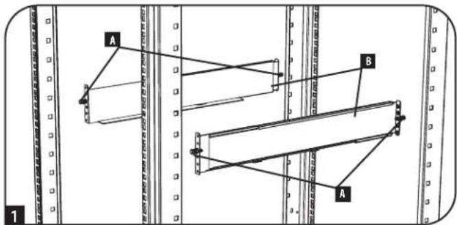
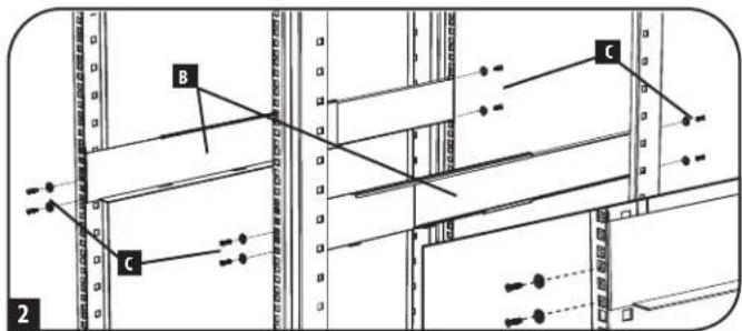
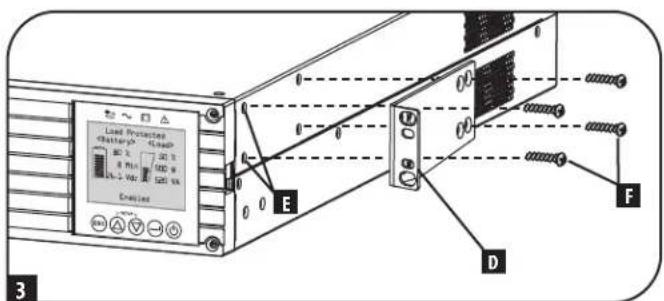
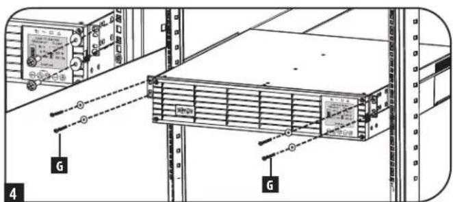
YcTaHOBKa
MOHTAX BODhopamHyTO CIOky
Ima MoTAta I5BbIKOTo 2UBOHOHOpAMHyTO CTKky Tpe6yETcKOMnNEKT Ira yCTaHOBKn B OndopamHyIO CTKky Tripp Lite (MoJIb: 2POSTRMKitWM, npHO6pTaetc oTJeBHO).IopAdoK yCTAHOBKn CM. B pKOBOCTBe Nol30BaTeY cTAHOBOHOrO KOMnEKA.
BepTnKaJIbHbI MOHTaX
BaWbMnMoKcT MoNTpOBaTBcB BBePmKaJIbHOM NIOJKeHHm C NOMOuBdoNIOJIHHTeBbHX OCHOBaHmIra HAnOBHou yCTAHOBKn,peaMzYEmbIXOTdEhBO KOMnAHNHe Tripp Lite (MOeJIb:2-9USTAND).Pm moTaTae W5Pi Ha perynnpyEmbx OCHOBaHHx Ira HANOBHou yCTAHOBKn yBeDntecb B Tom,уTO XX-NanEnb OpaMaHa NlueBoE CTOpOHoBBepx.

BHIMAHHE!
Bce IVbIaHTc KpaHne TaeKeIOBeChbIMn. IpOeBnIte octopoxhoctb npix noDbemn MOtaxe. PpN noDbemn MoTaxe IVINonb3OBaTeBdoJxhen oecneuHb er yctOnuBoe noOnKeHne.
KK-naHb moKet nobopauhBaTc nIe 60ee yDobHO npCmOTp npBepTHKaHbOM nOIOKeHN H5I. Ine ee nobOpota BCTabTe Hebohuyo OTBePTky mNpyrO INCTpymENT C nNOCKO KPMKOB INPpe3n CIO6O CTOPBOHt OT KK-naHbN. BbIDINbTe naHb, npOBepHHTe ee DIOJXHbIM O6p3OM u BCTabTe O6pATHO DO UENYka.

BHIMAHHE!3neKtpuecka npoBokda nCnner He 30nnpoBaHa. BpaueHHe nCnner DOnkHo npOn3BOnItc KaBAnuPpOBAHHbIM cepBncblm nepcoHaiom 3neKtpotexHnueckoro npoHnla.


TIPIMEYAHNE IIO HACTPOKE BHEUSHX BATAPEI
PnHcNb30BaHH BHeuHnx 6NoKOB aKKymyIaTOpHbX 6aTapei C N5Pi Hx CneNyET yTaHaBnBaTb B COTBETCTBm C DOKMeHTaUmei NO MOHTaKy/YCTAHOBKe, NOCTaBnaEmoB KOMnEKeC KaKdbm 6NoKOM aKKymyIaTOpHbX 6aTapei.
3TN Moen HbCemctBa SmartOnlnepeymatmbaot Bo3MOKHOCTb AToMaTHueCKoI paocno3HabHnI Do Qtebipex COBMEcTMBx 6IOOB AKKyMnTOpbix 6atape Tripp Lite Smart. Kaekdb 60k AkkymnTOpbix 6atape Tnna Smr Chabcken pa3beom Dn Iepaun daHHbx No KabEIO, OeCEnuBAOUM Bo3MOXHOCTb AToMaTHueCKoR paocno3HabHnI NactpoKn Do Qtebipex BHeuHX 6IOOB AkkymnTOpbix 6atape Tnna Smr, NOKNOUeHNbIX K IBN. B Cnyae Heo6xoIMOCt HAcTPOKn 6Ooe Tbeipex BHeuHX 6IOOB AKKyMnTOpbix 6atape BCE 6atapeHbte 60KN DOLKHNb HaCtpanBaTc c NOMOUs IporpAMMbHaCtpoKn BHeuHX 6atape Tripp Lite Ueep3 NoCedobTehBnHnnpTbNII. PIn BBINHeHm Taokn HactpoKn He NOKIOuaite KOMMyHKaioHnhBe Kaebn 6atapeSmart Hk KOdHomNy 3BHeuHX 6IOOB AKKymnTOpbix 6atape.
YcTaHOBka
Yka3aHnno MoHTaKy 3neKtponpOboKn dJa JxctKoro Ka6eNbHO BBOda N BBIOda (OnuHOHaBHO nIra OTdEhbix MoDenei)
PnmueyHMe.MoMeHT3aTAAK:1H-M).
BHIMAHHE!IIOKNIIOHNE DAHHOTNIAOJIKHO IPOIN3BOIDTBcTOnBKO KBAJIINHMIUPOBAHBMcEPBCNHBMnepcoHAnOMeKETPOTEXMHueCKTOIpOHN.PnIPBbIOHHeHmCoEHNHeHn HEO6XIOIMOy6EDHTCBtOM,TOCTeBOeNTAHAHE.10kOIOUHcNOIEpOBoDAKABEnK3a3EMNIOUeMy3axMMykopnyCa.3a3emNIOuNipOBoO6raTeNbHO DIOJENHIOAOEINHbCpEBbIM.
Heo6xOIMO co6HIOeHne Tpe6oAHnn K KOHpypaun BxOHOH LIMHH, HOMHNAY ABOMATueKOro BkKnOyateNn KaHbpy npOBODB, N3NOXeHHbIX B Ta6nue BxoN BbIXoN 6I: o6iee onncane, npCTabJIeHHoB D daHHom pa3dene.
PnmeHne. OtnbIeMbIe moJIbOcHauTc BxOdbHm WHypom NpeMeHHoro ToKa co WtncBbHm pa3bEmoM TnHa L6-30P. B Cnyae HnoNb3OBaHn 3ToT oHypa nepeMeHHoro ToKa MeHOTc HOMHaHbIbe 3NaueHnMoUHOCTn Ha BxoBe/BbxOxe HII. Boone npOpa6hna HfOpMaun ppeCTabLnHa Ha 3aBocko TabnKHe HII.
- CHMNTeTexHONORHueckyK KpIbIky, paCnIOJooHeHHyO cnPaba O TBbIbMbIbX OTBepCTn IJIЯ JcTeKTO RaBeBbHO R BBODa/BbBODa (CM.HNKe), IJIra oBcepeHnIaocTyna K bIoKy 3aXHMOB.
PnmueyHae. HaknKa c3o6paekHem CEmbki KcEMMbHx CoeHNHeHH HaxOHTC HbTbNbHO CTPOHE TEXHOONMueckO Knblk
- Ipo6eIte OTBepCTM NOxOaHux pa3MePOB DnIOKIOUeHJe KcTKo Ka6bHO BBOHa N BBIOJa.
3.YctahOBITE n npHKePHTe pa3BeMbIC KOMIeHCaTOpAMHaTaXeHHN (noCTabnAeMbIE B KOMIIeKTe NIN PnHO6peTaMbIE OToBbHO) KOboOnOue KeJcTKOro Ka6ebHOrO BBOda. - IpotaHHTe Ka6eB Yepe3 KOMHeHCatOp HATaRHeHnA.
PpmeHne. BbXoHoi KOMnEHCatOp HataKeHnpaCOnaRaetc CBepx, a BxoHoi KOMnEHCatOp HataKeHnna CH3y.
- PoiCoeMHHTe KaJbI npoB, K 6nKy 3aXmOB, KaN oKa3aHO HKe. (HKe CM. pInmuayane OTHOCNTenbHO Tpe6obAH N yCnuHIO 3aTAAKK).
- 3aTAHNTe KOMnEhCaTOP HATXKeHn.

KcTKn Ka6eBbIbBbOaBbOc KOMneHcATOpM HataKeHH BxoHbIe N bXbOHbIe 3aKMMbl
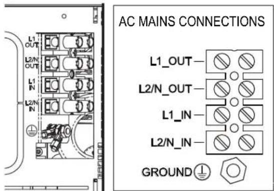
PnmeHne. Moemt 3aT8Km: 1 H.M.). NocTabAeBmB B KOMnEKe TakoHeuHKn 3a3eMnIoo npoBOOHHa DOJNkEh 6bTb CoDmHc CO UINHbKOI 3a3eMnHn, KAK nOKa3aHO HA pUHyke. PnOBo Dnla 3a3eMeHnO6OpyOBaHn DOJNkE COOTBeCTBOBAtb MMNkE N8 C BHEHMm DNAMetpom 8,71 MM INBHTpeHHM mDNAMetpom 4,3 MM.
YcTaHOBKa
Bxod IVbIXoN IVI: 06uee onncanne
PnOJHOBpeMeHOM HkaTmN Obox KhoNOK B pexKHe HaaybHoY cTaHOBKn IBI nocEnHM aBtOMaTHueCKn BbXoHT N3 peKMaHaaybHoH yCTaHOBKn.

KhONKa ESCAPE ("BbIXOД") :dAnHbI ΕπIeMHT ynpaBnEHn BblIOHReT TPN OCHOBHbI ΦyHKUH: OTMeHa aBaPmHO CMrHn3aUH, yCTpaHEHne HcNpABHOCTM N OpeaUM Bo3BpTa K npdeIduSyEMy 7ary /OTMeHbI 3aDaHHbIX DeiCTBm.
IpyOTMEHbI ABAPINHOI CNIHAN3AUHN HNI HAKMITE Ha 3Ty KHOKNy. B CNYaae BO3HKNHOBENH HOBOY cpaabBaHNAABAPHHOHN CHHAN3AUHN 3ByKOBOI CMHAI NOdaTcR CHOBa.
Ig OTMEHbl 3aAnHoro deiCTBn HIN B03BPATA HA OIN H YPOBEHb HA3A B peKIMax IepeMeueHn HauJIbHOY cTAHOBKn HAKMITE Ha 3Ty KHOKN, KAKIOKA3aHOHa 3KpaHe.
BnHaayalbHoro 3KpaHa
KK-3KpaH na nepenne Hnne HnnppebBnoe npedocabne HnHOpmaun o paote NBc nncnb30baHem hauNbblx 3kpaHOB HOPMAIbHOFO PEXIMA u PEXIMA IITAHNOT BATEP, HA KOTobpIX peryraHOn OTObpaiaOra paoouy peKM, coCToHHe 3aumTb, peKM TINAHM IN PAJpaOuNX napametPOB 6atapei HarpyzOK.
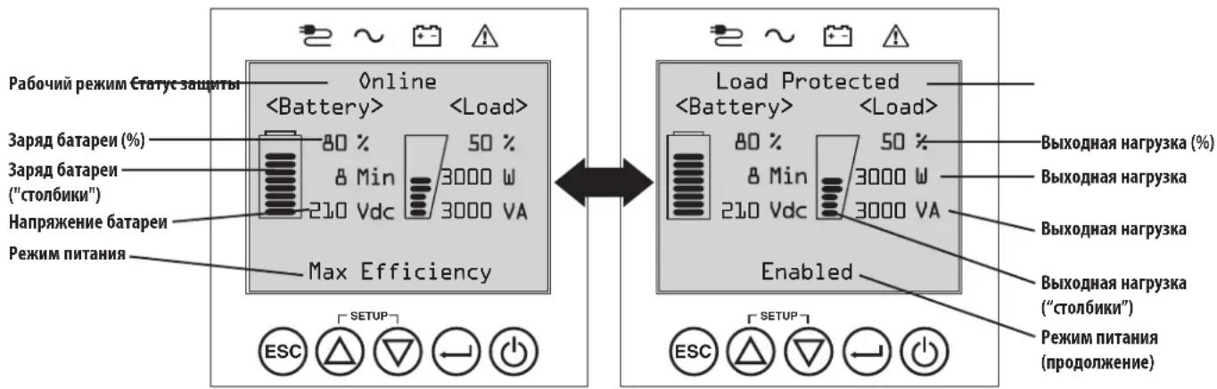
Haayalbhe 3KpaHb HopMaBho pexMma
3Kcnnyataua
IopKIOUeHne K OCHOBHybIM 3JIeMeHTaM N HaayabHyb3aynck
I Podkliouchenie N5N K 3NeKtPochna6KeHnIO
Bau N5I DOnJIeK 6bITb NOkIIIOUeH K BbIeJIeHHOI IINaTHIA, O6cIeYBaIOSeI IOCTaOHTHb IINr Hero TOK. Jnla MoJeI c pa3beMOM L6-30 Tpebyetra ABOMaTHueCKN BbIKIOuATEb IyCTAOHBK BYHTPN 3aAHN Ha 30A. Jnla MoJeI c JcckTKM Ka6eNbHbIM NOkIIIOUeHMe CM. pa3dE YCTAOHBKa, Ta6nnu BxO u BbxOg N5I: o6eeonncane HOMHAn, yka3aHHbI HA Kopnyce N5I.
2 PoiKJIouHeMe o6OpyOBoHaHn K N5P
Pnnoaue BxOJHO RHTAHN HbI nepexoNTB pexHM OXuHaHn (Standby), npOn3BOJNTc3apJa 6atapei.
IbHnMoepnpeHa3HaeHnpoepHAnma pa6oTcno6HOCTn TOnbKO cTeBOrO, cepBEPHO H BbUcnHtBHO 06OpDobAHN.
PnmeHne. Ecn npenonaraercpeynnpoBaHne Harpy3K, co3daeMoN 60pOyDobAHMe, To He6xmo 06ecneHb er oNDIOueHne K rpynnce perynpoBaHMe Harpy3K.
BknioucheMe IVI
HaxMnTe Ha KhoNky POWER ("TINTAHNE"), yedkmbaiTe ee B TeueHne 3 ckyHdo HauHaNoaH 3BykoBOrO CrrHana.
4 Bb6op yBaIka
Pn nepBOM BKNHueHn NITAHN I5N 3aRopaTaC bTeOIOIOHb HmIKKaTOp INPUT AC ("BXoI NITAHNIEPEMEHHO TOKA") , a Ha XX-3KpaHe nepdne NaHn NOIb3OBATEHn PnpdaeraTc BblpTa83blk.
Bb6epnTe npennoTneBHHmIaCe6a3bIK npn NOMOON KHNOK UP /DOWN ("BBEPX/ BHN3") , noce yero haxMMte HaKNky NEXT ("DAJIEE")
Ha HHTepfchom 3KpaH NoBHTcNoTBePckJeHMe Bb6paHHoBapnA T C BO3MOxHOCTaMn BO3pTa (HaxMMte BAC/“HA3AD") Mm NpeXoJa K cneyooemy 1ary (HaxMMte NEXT/“JANEE”
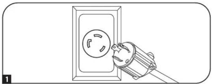
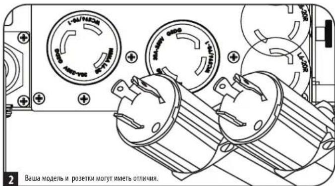
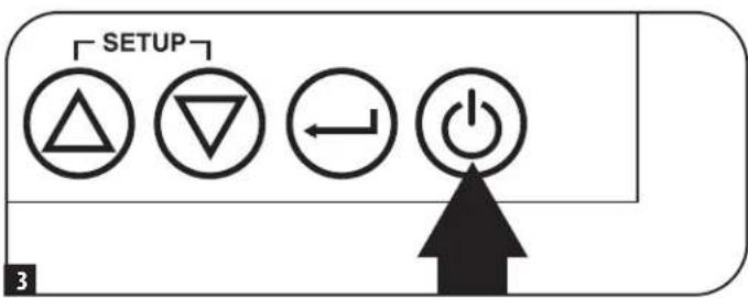
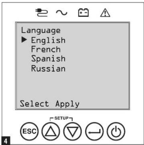
3Kcnnyataua
Bb6oppeKIMaNTaHnA
3aTeM MBn npednoxmt Bb6paTb XeNaemBPOWER STRATEGY ("PEKIM NITAHNIA").
Bb6epntpepnonttehnydnacepePEXMMNTAHNnnpnoomKHOKUP/
DOWN ("BBEPX/BHIM3") 7, nocne yero Haxmnte Ha KhoNky APPLY ("PIMMEHHTb")
Paboyme xapaktepeNTKKaJDOPOPEKIMNAITAHNcM.BnOpa3dAnxBapnantbI
Bb6opa pexmmOB nHTaHnA PexmmBa pa6oTb IbIpa3dena"3Kcnnyatauua."
3aahanne napon
3aTeMbI pIpeIooXHTaIaTbJxJaembI PASTWORD ("TIAPOJIb").
HaTpoKa DnCTaHcNHOHHOrB BKJIIOUeHn/BykJIIOUeHn
DHaHnA phyHKnI npEHa3NaHeHa I npeKKnueHn IVB pexHM paobTo b no 06xOHO uen n pnn HacTpoKe DuctaHNOHOro BbIKNoeHn (Bbl) mnn B peXm PntAHn O T ctn npn HactpOke dNtAnuHnHO BkUoeHn (BKl).
PnmeHne. Pnepd AHTBaeHm Enoe HnnepeHnroE 20a HxOeOBHbM Tpe6oBAHnA
Pnme. HepekAkhmaeH cyHKmRtomeON ("IcTahunHOe BKnueHe) Heo6xmoN pnoBepHT haMne nepMeHHoro ToKa hBXOe H ercoTBeCTBVEyCTaOHBNHBM Tpeb0AHMM. 4-KoHTkTHbX 3axHMOB paCCHTAH Ha npoBaOA kAnb6pOM 14-30 AWG c dnnHoa3aHcTkn 7 MM. BnHb M2 dHnKcaHm 3aKmOB DOnhbl 3aTnBaTcC yCNMeM 0,22-0,25 H-M.

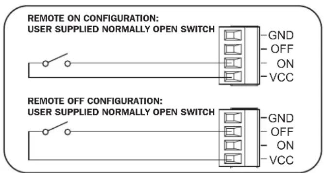
1 PtoKIOUeHne BHeuHnx 6aTapei
VHOpMaUaO COBMeCTMlbx C BaUMN I5I MoJeAix 6IIOKOB AKKymnTOpbXb6atape IN MAKCImaJIbHO DOnyCTMbX KOINueCTBaX PpNBeDEHa B NOpa3Ie NOMI KIeKTyOuHcne IaONKpeTHbIX MoDenepa3Dena KpaTKe OINCAHNE. Y6eITecb B TOM, 70 To Bb6paHNb BamN 6NOK AKKymnTOpbXb 6atape IMeET HApRAJKeHHe, COOTBeCTByOoEe Yka3aHHOMpy PAOM C pAsBeMOM IINPOKNIQUeHMe 6atape K BAWeMy I5I. HApAY C npOIIeHm E BpEmHn ABTOHMHO pa6Otbl, POKNIOeHMe DOONIHNTbIX BHeuHIX 6atape INPBEDET K npOIeHNO BpEMHn 3apdKn. BCE Yka3aHnno yctAHOBKe n HAuaJIbHO hAcTPOKe CM. B pyKOBOCTBE Nl630BaTeBA6ILOKA AKKymnTOpbXb 6atape. IpExZe Bcero Heo6xOIMmo pIKPKeHTb PpOBD 3a3eMEnHn 6atapeHOrO Ka6eN K 3a3eMIAUeMY BINTY, pACNOJOeHHOMpy PAOM C pAsBeMOM NoCTOHHOR TOKa. POnCoEINHTE Pa3bE Moc TocTHOR TOKa INy6IteCBB TOM, 4TO OH BCTAbEN Do yNopa, NoCeYe 3aФHKCUPyIe Ero pIn NOMOUI BnHTa C HAKATAHHO rONOBKO. PnN OKNIOeHmN 6atape Bo3MOxHO He3NaHTbeHoe NCKpo6p3OBAHNe, 4TO pndCTABnREt c6oB HopMaJIbHO eABHeHne. He NOkLIouaTe IN HE OTKIOUaHTe 6NOKN AKKymnTOpbXb 6atape BO BpEMa PabTo b I5I B peKmme NITAHNAOT 6atape.
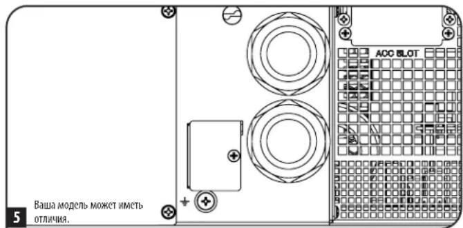
BHIMAHME!IgnoeueHnToHoro nporH03aBpeMeHHp6oTbI npOtobpaKeHHOCTabWeroCBApeMeHHHaKK-dncnne HnHOpMaunonHbix 3KpaHax nporpamMHO oocneueHH npu HauHHN NOkKIOeHHBX BHeHHX 6koB aKymyAHTopHbIX 6atape HeoXoMDoBblnHHTb HAcptoiKy CnOJb30BaHHem KOMMyHKauOHbIX Ka6ene Ipn 6atape Smart (do 4 6koB aKymyAHTopHbIX 6atape Smt), KK-dncnne nepedne naehn nn pa3pa6oTHORo KOMnHne Tripp Lite nporpamMHO oocneueHH NaCTpoHH BHeHHX 6atape. Cm. nDpa3den HAcptoKa BHeHHX 6koB aKymyAHTopHbIX 6atape Pa3dena 3KcNpyataua.

Pn yctahOBke BheHrero 6noka akkymyIaTOPbIX 6aTapei Heo6xOJmo yUHTbIbTaB Ce npdynpKdHm OTHOCHTbHO BHeHHX 6aTapeHbIX 6nOKOB, nIOKeHHBe Bpa3Dene BaHXIbe Yka3AHmNo TExHKe 6e3oNacOCTHaCToIgero pyKOBOcTBa, H BblONHt b Yka3AHmNo yCTaHOBKe BHeHHX 6nOKOB aKKymyIaTOPbIX 6aTapei.
BbIaBHeHne uYcTaPahEnHe HncnPaBHoCTeN JxypHaI co6bITn
B npBHeHn Hxke TaBnue CoepKHTc pa3bXeHHe COo6eHn O HeCNpABHOCTa XbI N ppeDypeNTeNbHX COo6eHn, DocTyNbIX Chepe3 XyphAn co6bTn, BvBoIMbix Ha Kk-3KpaHn C n POMOsbIO npOrpaMMHOro oecneHn PowerAlert, a TAKKe ppeNaeraMbe BapHaNTbI yCtpaHHe N pOBeJEM no KaXDoMy COo6eHn O HeCNpABHOCTn / npDeynpeDInTeNBHomOcoo6eHn.
3aMeHa BEHTUNIATOpOB
B HopmaJIbHbIX yCIOBnAX opHHaJIbHa BcHTIIaIIOHHa YCTAHOBKa npocnyKNT HeCKoJIbKO neT. bNOKn BeHTINATopoB npedyCMatpHbAOT Bo3MOKHOCTb 3aMeHbI. CmeHbIe n3dEIMN MOKHO HauTH Na CTpaHmUe tripplite.com/support.

BHUMAHNE! 3neKtpueckaae nIb nHTaHnBEHTnAToPOB He 3OInpObHa O t cTe NepemEHOro ToKa. Ipeed 3ameHoB BeHTnAToPob BbIKIOHTe NTaHHe IVII. 3aMeHa BeHTnAToPob DoJHKa npOn3BOJntcb TOnko KBaHnHnUnpOBaHHbIM cepBcHbIM nepcoHAnOM 3eKtpoeXnueckoro npOphna.
IpeH N3BLeueHem BeHTnTApOpbIX 6NOKOB CLEyET 3aONMHITb opHeNTauu BOHTnTApOpB. IJI HAeJaee yCTAHOBK IN NOKIOUeHMA BeHTnTApOpB IX nepBOHaayabHnaopHeNTaun DoJXHa 6b1b coxpaheHa.
1 BbBepHnTe 8eCTb NpeDnHX BNHTOB H3 NmEeBOI NaHEn I6Pn CHMnTe ee. NobecbTe naHEnBa HmEOUIMC DnA 3TOF KIOUOK.
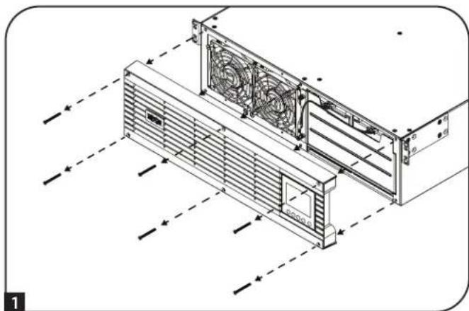
2 Dn3aMeHbBENTHTOPa,paCnonaraOIOcRcJIeBOHNINpABOBCTOPoHB, BbBepHNTeOTBepTKoCnIOCKMJANOMIeBBiBepxHmNpabBbHnxHBMHTb, 06ecneuBAHOme KpeIeHHe KaKdOro BEHTTAPota.

3 OToeMHHTe Ka6enb(-N) BeHTnIaTopa(-OB), paCNoJKeHHb(-e) CneBa oT Hero (HIX).
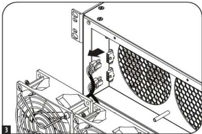
4YCTAHOBITE CMEHBB(-E) BEHTNATOP(-B).NoCoEOHNHTe Ka6eb(-H) B TOM JXE NOPRAKDE, 1TO Hn HA WARE 3, n npNKpenITE BEHTNATOP(-B) K N6Pc coXpaHEHem Mx paCNOJXEHn I OPMENTAUIN (CM.War2).
5 PnKpennte nueeyo naHEnb o6paTHo K N6Pi 3aKpenNTe ee c nOmoBIO BHTOB, BBBePhyTbIX Ha Ware 1
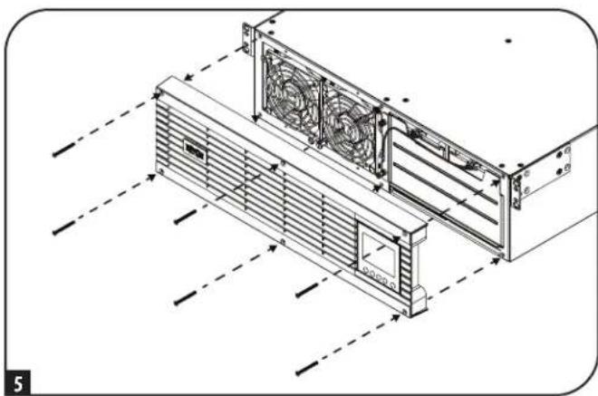
XpaHeHne nTexHnueeCKoe 06cnyxHBaHne
Xpahene
Chayana OTKIIOHTTE CBOI IV5P: HAKMITE HA KONKY "OFF"(BbIKI) pAOM c PO3ETKAMU IV5, NOCE YEROTCOEHNITHE WHPY NTAMHNA OHTACEHNO PO3ETK. 3aEM OTCOEHNITBE C6 o6obyoAHNE BO IV36eXAHNE CAMOPa3pda 6aTapei. EcN Bbl PAnHpyete XpaHNTB IV5B TceHME dINTELHO rpeNoBa BPEMeHH, TO cIeJyET NIOHCTbO peEzapKaTB 6aTapeu IV5P OdH pa3BTPn MeCa: dIra 3TOPO nDkHIOHTVE IV5K pO3eTKe nepeMeHHOR ToKa i daTe EMy 3apAHTBCB a TeueHne 4-6 qacob. XpaHHeNVE IV5C pA3pXeHHbIMM 6aTapeMn B TeueHne dInTELBOr cPoKa MoKeT PnBeCTN K HeBO306HOBIAEM NoTepe IN EMKOCTN.
Texnueckoe 6cbnykBaHne
Ha npno6pehenoe BAMM 3dennme Mapk N Tripp Lite pacnpoctpaenrcae TepnMM, yCNOBN KOtpoH 3NOKHeBb H cTcHsE m pyKOBOCTBe. KpOme toro, kOMNAHTRipp Lite npednaerat pIporpammpacwnpenHHraPantm H o6bkeTe. Boee noopnbna HOpmaua O texnuueckom 6cnjxmbAHnn 3NOXea Ha cTpaHnue trippite.com/ support. Paped Bo3BPaTOM CBOero 3dennn B cIax Txnueckoro 0cbnyuHBnA nPoCb6a BblONHHT cbNyUOnne DeETBnA:
- BHIMATEbHO 3UYtE NopAOK MOHTaXa 3KcIpyaTcHn yCTPoTcTBa, PnBBeEHbB HAcToaHcM pyKOBOCTBE, BO 36eKaHHe IpO6nem, KOtopbIE MoTy B03HKNHyb XoDe pa60tBb H3-3a HEPaBbHOrO NOHMAMH NpBBeEHbIX B pkoBOCTBE yka3AHN.
- Ecn npobemy peunb He ydaocb, He opaaiTcB K npadabuy H Be 03bpaaaTe u3dene emy B 3om cnyae nocette nHTepHET-CTpauu no aepcy triplite.com/support.
- EcmBo3HnKwA np6bEey npObeHnpeMoHTa nnTexHmueckoro 0cbNyXuBaHnna, 3aIInne Ha cTpaHnuy triplite.com/support n Haxmnte Ha cBky Product Returns (Bo3bpat 3dienm). 3decBb moKeTe 3anpocmb Homep Rerumed Material Authorization (RMA - papeHHe He BA3bpat MATEPnAbOB), KOtpbmy He6xOIMn IpnpoBeHnne TExHcckoro 0cbnykBaHnna. Iyra 3aOnHHeN ToIPOCTO OHAnH-OpMbNoTpe6yctya Ka3ab Hmep MoEni N cepHbHmop Bauero H3denn, a Takke o6une CBeHnne Ookynate. Homep RMA BmeCe C yka3AHnMM No TpaHcnpTnpOBKe 6yET HapBaHn BAM No 3NeKtpHOH NoYte. Ha KaKe Me bTo Hn b6bIO y6bTK (PpMaBle, KocBeHHbe, NOCJeYUe NeM NblBaHHbte oc6bIMn 0cbTOaTEbCTBaMn), CBzAAHbce C TpaHCnpTnpOBKn H3denn B adpec KomnHaH Tripp Lite mE ee yonlHomoeHOro cEpBcHOrO ceHTpa, JeCTBne rapaTHm He pacnpocTpaHreTc. CTMOCTb TpaHCnpTnpOBKn H3denn B adpec KomnHaH Tripp Lite mE ee yonlHomoeHOro cEpBcHOrO eHTpa DOJXHa BOnLAeHa ABaCom. Homep RMA DoJxHe 6b1b YkaznHa H BheUe HcTpope YNAKOBKn. Ecm Bo3BPaT H3denn PpON3BOIDTC B nepNO DeIeTBNr rapAHTM, To He6xoDIMO pInIOJXtB KOnIO TOBAPHOr eKa npOdaBuCA. Bo3BPaT H3denn DnI npOBeHnne PemOH TaII TeHXuECKOrO 0cbNyKBaHnBA dnJxEN PpON3BOIDTCs A3cTpaXOBaHHbM IppeBO3WMKOM IO aDpcy, Yka3aHHOMy B OTBete Ha zainpocHomepa RMA.
TapaHTnHbIe 06a3aTeNbCTBa
OrpanuHcHnraIpaHTnI cPOKOM 2 roDa
KOMnHnTRPP LITE rapAnHpyet OTCyTCTBNE deeKtOB MATEpANOB IN3rrotobHeNcBxN3denn, BkIOUa76bAtepeB, BTEcHMeIbXNET C MoMeHn Hx NepBOHaunBHO NOKyKN. IIO cTeueHN 90 dne C MOMENTa NKoynKbO63aTeBCTBA KOMnAHnTRPP LITE NO hactoaeepraHTNH ORPAnuMBAIOCT 3aEMHeN DetaneB b TAKIN DEeKTHBxN3dEIMN. JINI pONUYHn yCNYr no daHHn RAPANTH Heo6xoDmO opaPTNTCB No TEePHOBy B KOMnAnHnTRPP LITE IMN ee ABTOPN3OBAHNb CCEPBCHN. WIDENJIOJOLNb6bTbO3BpaueHb B KOMnAnHNO TRPP LITE mnn ATOBPOT3BOAHNBc CEPBCHN CEHTRTP TRIP LITE c npDoJIaTOn TPAHCNDBxPACdoHn BOPOBQdAcbcRA kPAMn ONOHnEM BozHIKnwe PNOBNeMBoKUMYEMn, NOITBePjKaDauImDatY MeTo Eno pInOp6TeHN. DeiCTBn HAcTOnien rapAHnHe paNPocTPAHETn Ha 06OpDnABHnne, NOBpeJEnHoe B p3yNbTAbeApBN, NEbpeJHOO BrpAuaHEIN HENpABINHOro MCNBO3aHnA, aTKAE BVDMaON3EHeNKeKAKMb To Hb6bnOe. DeiCTBn HAcTOnien rapAHnP PaNPocTPAHETc TO nBko HA nepBOHaunBaHOro NOKyPaNer, KOtbp IdoJenHn HADNeKaUImo6pzmAor pboBpTaHOBn.
IapantnHa Bce cetBbte fHbtpbT RTRPP LITE ytpaunbaot Cny B cnuyae Hx noeknoeHna K bixOdy n6oR O51. IapantnHa Bce W51 TRPP LITE ytpaunbaot Cny B cnuyae noeknoeHna KaKoro-n6o ceTeBor0
3A INCKIIOUYEHME IPEYCMOTPEHbIX 3DEC B CYAEB KOMTAHNA TRIPP LITE HE INPEIOCTABNERT KAKNX-IMBOBHBIX ININIOPOA3YMEBAEMBX TAPAHTM, BKIOUAYA TAPAHTM KOMMEPECKON PIPINOHOCTM INPINOHOCTN DIIKAKOINIO BOHKPETHO CEIM. B Hekotopbx Wtatax/rocydapctbax orpaHueHne INIKIOQUHeNE NOpda3yMeBaemBX rapaHTM He donyckaeTc; cneobateNbHO, bblweyka3aHHoe(-ble) ORpaHueHne(-a) ININ CKIOUYEHNE(-a) MORYT He paacnpocptpaHbTa h Naokynatena.
3A NCKIQUYEHME IPEDYMCMOTPENHbIX BIIIE CUYAEB KOMNAHIA TRIPP LITE HN PIPKAKNX OBCTOATEBCTBX HE HECET OTBETCTBEHHOCTM 3A IPANBIE, KOCBEHNBLE, CUYAHNBIE MNIOBOOHIE YbBTKN I50 ybTKM, OPNEJREMBIE OCObIMN OBCTOARETIELCTBAMN, BO3NHKAOKLIUE B CBA3N C ICHNIIB3OBAHMEM DAHORIO H3DEINRA, DAAKE B CNYAEE EE INHOOPMPOBAHNO O B03MOXHOCTN HACTYJIENHA TAKHX Yb1TKOB. B aCTHoTHCN, KOMNAHIA TRIPP LITE HN Hecet OTBETCTBEHHOCTM 3A KAKHE-Ni6o H3deepKn, TAKHE KAK NYUeHNHE pnp6blm mno doxOdi, notepe obopyoBaHnne, notepe BO3MOXHOCTN McNoBobAHn o6opyoBaHnna, noTePA npopammmoro o6ceuehenn, noTePA daHHbx, paXoDbI HA ZAMHHTENy, ypernyipouBaHne npTeHs TpeTBx niu nip
HdENTnKauNHOHbIe HOpema COOTBETCBHOPMaTHNBHM Tpe6oBaHmM:
BceHx cepTHKauHn H cooTBeTCTBHe HOpMaTHNBHM Tpe6OBAHnM H ono3HaabAHn N pno6peTeHHMy BAMn K3dENH M apKn TrippLite npuCBOeY hNkAaHBn cepHbHbHomep. CepHbHbHomep pacNoIaraeTc H 3a0DcKo TaBnUe BmCtE Co BcEMn Heo6XoMbIMn O tMeTcKa m O pmeMKc N ppoey InhOpMaueH. Pn 3aPocE InhOpMaun O cOoTBCTBm DaHHOrO N3dEnma HopMaTMBHm Tpe6OBAHnM o8aTeJIbHO yka3bMaHTe erO cepHbHbHomep.Homep cepHN He cndyet Pyta b T copOBm HAmMeHOABHm K3dENa IIN Homep om erO moen.
TapaHTnHbIe 06a3aTeNbCTBa
Texnueckne Tpe6oBAnH FCC nna moJeene c donyckom FCC knaccA:
JaHoe yctpoCTBO COOTBCTBYET Tpe6oAHMaM qactn 15 PpaBn FCC.ErKcNpyaTmaOnycaeTcnPco6nOHeHN CNEyUxuXbDBy xycnOBn: (1) daHoe yctpoCTBO He moKet co3daBb Bpehix nomex, n (2) DaHoe yctpoCTBO DOJHKHO bPTb paccHTAO HAIObIe NOMEX, BKIOUaA TE, KOtOpBe MOrY OKa3bBaTb He6NaorpmTHOE BNHHMe H er o paBtoY.
PpHmehn. dAHHoe o6bOaHHe npno nCbTaHn H pnn3HaHO COBtBcTByoUmm OrpaHmHnM mIrauHPObX yctpoCTKnacca A cornaHoc hnt 15 PpaBn FCC. 3n orpaHmHnPaaccnabHa ha o6bcneHHe npyOBn HAaunbTo BPedhNb N0eMx npn kcnlyaataum daHORO o6pOBOAHn B npomblneHbX ycOBnX. DAnHOe o6pOBOAHn BbpabtaBbaet, nKMOCT Knyatb paNaOHOTyHNEprn, a taKae - B cnuye HecoBIOHnTre6OBOAHn pykoBDCTBa nObnOBeTn prn YctAOBKe HckNpyataum - Moket Co3dABab TbeNHE bomeX cpctdBam PaIOOCBzM. 3kNpyataun daHONo O6pOBOAHn B xINOM NOMEuHn C 6bLbWBPoARHOCTb MoKet Co3daBt BpeNMeX, B cnuye Yero NlO3bOteNo Notpebyetc YcTpanht TaKHe N0MeX 3a CboBcCTBEHNb ChET. PIOBbTeBn 683an EKcNpyTbPOBaHn C eKpaHnpOBaBHMM KabEAMn N p43bEMAMn. NIObe N3meHHe NIM MOnDfKaUaNN OTOHOHO O6pOBOAHn, He OdoOpEHn B RAHOJ fOpme KomnHne Tripple, Morynpmbctn K IinuHHeNNO nOBoTbAm npaba Ha KcNpyatauAoHOHOO6pOBOAHn.
Tpe6oBaHn3MCDnIaMoDenei CceTpHKnKaTaMa3MCKaTeOpuN C2 (nAOTdEhBbIX MoDenei):
BHIMAHNEI DnHHbN HbI OTHOCHTK Kateropn C2. Pm HcnoB3OBaHb W bKnIOM NOMEeHN DaHHoe WdJeMe MOKeT Bb3BaTb PaHONOMEx, B cnYae Yero nolb3OBaTeHMOxomet 6blt Heo6xOIMnpednnHrT DoonHHTelbHbe Mepl.
HΦopMaunno BbIOnnHeHHIO Tpe6oBaHm DmpeKTHBbI WEEE nla noKynaTeen HnepepaOHTKOB npOdyKmN KOMNaHm Tripp Lite (AIBNAUxXcpe3ndentamn Ebponeckoro co103a)

Cornacno nnonokenHm DnpekTbbl 6y Tnnh3aun OTOxOBn EeKtpneckoro H eKtpnHOrO o6pOyBaHn (WEE) nONnHtEnbHbX paCnpApKeHHIO, npN nOKynke nortpe6ntanMHOBOrEeKTPnckoro Hn EeKtpnHOrO o6pOyBaHn PpOn3BcTa BOMnHn Tripp Lite OHn NOnyauo npabo HA:
PpOaJy cTAPoro 06OpOyOBaHn no npHHmny "oMH 3a oOHn H/WM Ha 3KbBbAeHTHOI OCHOBc (B 3aBMcMOCTN OT KOHKpeTHOI CTpaHbI)
Otnpabky HOBOro obopyoBaHmHa nepepaobTkNoocKe OOKHataeBhoBbIpaBoTkn eropcypca
YbeomJHeHne o COoTBcTbHn Tpe6oBaHnFCC, TaCTb 68 (ToIbKO dNCA)
EcnHcnoB3yemaHa 3aunHtMa Moema/4aKaP npnTCTbyet HopmaIbHoi paobTe TeneoHHO CTTo TeneoHnA KOMMAH Moket BpeMeHHO pnoctAHOBHTBaIbe o6cyHMBAHHe. PnHaHnHn BO3MOXHOCTN Bbl 6dyete ybeDMnHb 06 tom 3apaHee. B cnyae HeBO3MOXHOCTn PnpBaHTBHO ryeDMnHb Bbl 6dyete ybeDMnHb npi nePBBo BO3MOXHOCTn. Bbl 6dyete nocTabneHb I 3BcEChTOC b CBOe m npabe Ha noany JAnObBt B FCC. BaTa eNeoHnA KOMMAH MOET BHOCHTB NmCEHNEH B OTHouHEHN CBOMX TEXNHueCKM CpcDCTB, ObopyDAHNA, onepaui npoceDpy, KOTpBe MYr npenHTCBOBATn HaneKau Mye HKNIOHPoABAHIO BAeTo OBOPyOBAHNA. B 30m CnYae Bam 6dyete HapBaHEno PnpBaHTBHOye EBEOMLNEH CzEBIO pnoDCCTBt Bam BO3MOXHOCTB COxPAHENEA 6cnepeBOHO 6cbNYKBAMn. B cnyae BoHNKOBENAH KAKIN-NiNo pOboEM C 3aunHtMoMa/4aKa, oecNeeWbAEmo DAHBM OOBPOBaHnem, OHAKoMBteCb mHOFpMaOH OBO3MOXHOCTn POMeHTa /rapHTnBHX 6O3aTeBCTBX HA cTpanHe triplite.com/support. TeneoHnA KOMMAH MOET o6pmbTcR Bam C npocB6o O8kUHeHN DaHORO OBOPyOBAHNA OT cEtN Do TOFOMeHTA, KOta pNObEM aSyet YcPaHEA NH BY bYebntecB B 0TCytCTBN HcNpabHOCTe OBOpOyABNa. 3aunHtMoMa/4aKaHe Me MOET pOeHTBOBATCb KInHTEM. DAnHOe OBOpOBAHNE He MOKET NcNOB3OBACTB nIra pncOCTABNNH NlAHTBx YcNt TEoHON HOM KOMANHA. PodKnOeHNe K rypnoBbM aboHNTCKM NmHNM OCUeCTbNtEeNc To rOcUdAPCTBEHNbIM Taipam. (3a HfOpMaieh o6paaiTcB. BPrrHOAbHBn roCyJapCTBeHNbOpran No kOMMyhNBOM By 0cynKBAHNO HmnpraH2aQIO, pernaentHypouyoJe dertelhoCTBOCTBYOONKOMMEpeCKM cIyK6).
YTNH3aIINbIbIbIaTapei

yTnH3pynte H3dennr Tripp Lite. B Kauectbe 6aTaepen dnn I3dennm MapKn Tripp Lite McNoB3yTOC repMeTHuHbE CBHIOBO-KKcNtOHbIe AKKyMnATOpHbIe 6aTaepen. 6aTaepen npnrOdbI dnn rny6okoi BTOpHNO nepepa0fTk. TpeoBaHn no yTnIM3aUIN ONpeJeHHOTCA MeCTbHM HOpMaMn HnpabMn
3a nHΦopmaueH no yTHnH3aunn 6paauTceb B kOMnAnu Tripp Lite no teneΦohy +1.773.869.1234.
CamaA kAtyIaHbA HnHOpMaunu 06 yTHnHa3auu 6aTaapei npOxH 3denn Tripp Lite coepKnto Ha Be6-caiTe KOMnHaH TrippLite.
TnnoNueHmToHnHOpMaunu nepeiune no cneDyoue CsbInke: tripplite.com/en/support/recycling-program.cfm
KOMnHr Tripp Lite noctoHNO COBepuHcHTByT CBOIO pOdyuKIO. B CB3N C 3TMM BO3MOXHO M3MeHHe XapaKTEpHcTK 6e3 npEpaHntbHOrO yBeOMneHn. BHeHm BmpeAebhix H3dEmn MoKet Heckolbo OTOIaHcR O TnpCTabLeHHoro Ha FOToPraMx HIIIOCTpaUHX.


1111 W. 35th Street, Chicago, IL 60609 USA - triplite.com/support