DMCS60105HDS - TV Stand Tripp Lite - Free user manual and instructions
Find the device manual for free DMCS60105HDS Tripp Lite in PDF.

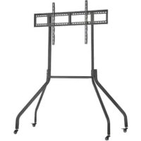
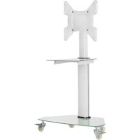
| Product Type | Mobile cart for flat panel display |
| Brand | Tripp Lite |
| Model | DMCS60105HDS |
| Maximum load capacity | 100 kg (220 lb) |
| Compatible screen size | Up to 60 inches |
| VESA standard | Compatible with most VESA standards (up to 600x400 mm) |
| Material | Robust steel |
| Casters | 4 sturdy locking casters |
| Locking system | Combination lock included |
| Adjustable height | Yes, via mounting arm |
| Usage | Indoor only |
| Warranty | 5-year limited |
| Approximate net weight | 25 kg |
| Dimensions (W x D x H) | Approximately 80 x 60 x 150 cm (depending on configuration) |
| Color | Black |
| Certification | Compliant with safety standards |
| Support | Tripp Lite customer service |
| Maintenance | Check every 3 months, clean with a soft cloth |
Frequently Asked Questions - DMCS60105HDS Tripp Lite
User questions about DMCS60105HDS Tripp Lite
0 question about this device. Answer the ones you know or ask your own.
Ask a new question about this device
Download the instructions for your TV Stand in PDF format for free! Find your manual DMCS60105HDS - Tripp Lite and take your electronic device back in hand. On this page are published all the documents necessary for the use of your device. DMCS60105HDS by Tripp Lite.
USER MANUAL DMCS60105HDS Tripp Lite
natural_image
Technical line drawing of a mechanical lift or cart with wheels and overhead railings (no text or symbols)Español 13 • Français 25 • Русский 37 • Deutsch 49

CAUTION: DO NOT EXCEED MAXIMUM LISTED WEIGHT CAPACITY. SERIOUS INJURY OR PROPERTY DAMAGE MAY OCCUR!

400 × 400/600 × 400
800×400/800×600
1000×600


DVD

WARRANTY REGISTRATION
Register your product today and be automatically entered to win an ISOBAR ^® surge protector in our monthly drawing!
tripplite.com/warranty


1111 W. 35th Street, Chicago, IL 60609 USA • tripplite.com/support
Copyright © 2021 Tripp Lite. All rights reserved.
Safety Instructions
NOTE: Read the entire instruction manual before you start assembly and installation.

WARNING
- Do not begin the installation until you have read and understood the instructions and warnings contained in this manual. If you have questions regarding any of the instructions or warnings, please visit tripplite.com/support.
- This product was designed to be installed and utilized ONLY as specified in this manual. Improper installation of this product may cause damage or serious injury.
- This product should only be installed by someone of good mechanical ability, with basic building experience and a full understanding of this instruction manual.
- Make sure the unit can safely support the combined load of the equipment and all attached hardware and components.
• Always use an assistant or mechanical lifting equipment to safely lift and position equipment. - This product is intended for indoor use only. Using this product outdoors could lead to product failure and/or personal injury.
Warranty and Product Registration
5-Year Limited Warranty
Seller warrants this product, if used in accordance with all applicable instructions, to be free from original defects in material and workmanship for a period of 5 years from the date of initial purchase. If the product should prove defective in material or workmanship within that period, Seller will repair or replace the product, in its sole discretion.
THIS WARRANTY DOES NOT APPLY TO NORMAL WEAR OR TO DAMAGE RESULTING FROM ACCIDENT, MISUSE, ABUSE OR NEGLECT. SELLER MAKES NO EXPRESS WARRANTIES OTHER THAN THE WARRANTY EXPRESSLY SET FORTH HEREIN. EXCEPT TO THE EXTENT PROHIBITED BY APPLICABLE LAW, ALL IMPLIED WARRANTIES, INCLUDING ALL WARRANTIES OF MERCHANTABILITY OR FITNESS, ARE LIMITED IN DURATION TO THE WARRANTY PERIOD SET FORTH ABOVE; AND THIS WARRANTY EXPRESSLY EXCLUDES ALL INCIDENTAL AND CONSEQUENTIAL DAMAGES. (Some states do not allow limitations on how long an implied warranty lasts, and some states do not allow the exclusion or limitation of incidental or consequential damages, so the above limitations or exclusions may not apply to you. This warranty gives you specific legal rights, and you may have other rights which vary from jurisdiction to jurisdiction).
WARNING: The individual user should take care to determine prior to use whether this device is suitable, adequate or safe for the use intended. Since individual applications are subject to great variation, the manufacturer makes no representation or warranty as to the suitability or fitness of these devices for any specific application.
PRODUCT REGISTRATION
Visit tripplite.com/warranty today to register your new Tripp Lite product. You'll be automatically entered into a drawing for a chance to win a FREE Tripp Lite product!*
* No purchase necessary. Void where prohibited. Some restrictions apply. See website for details.
Tripp Lite has a policy of continuous improvement. Specifications are subject to change without notice. Photos and illustrations may differ slightly from actual products.
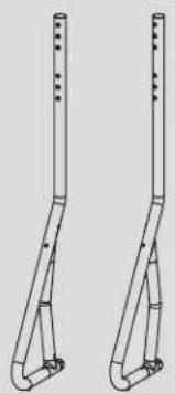
Component Checklist
IMPORTANT: Ensure you have received all parts according to the component checklist prior to installing. If any parts are missing or faulty, visit tripplite.com/support for service.
natural_image
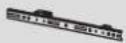
Line drawing of two vertical metal supports with evenly spaced notches (no text or symbols)A
(x1)

B
(x1)
C
(x1)
D
(x1)

E
(x2)

F
(x1)

G
(x1)

H
(x1)

I
(x4)

J
(x3)

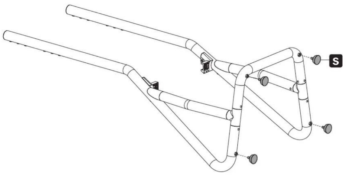
S
(x4)

T
(x1)
Package M

M-A
M5x14 (x4)

M-B
M6x14 (x4)

M-C
M6x30 (x4)
M-D
M8x30 (x4)

M-E
M8x50 (x4)

M-F
(x4)

M-G
(x8)

M-H
(x8)
Package P


M6x10 (x6)


M8x15 (x1)


M8x35 (x6)


D8 (x4)


M6x16 (x2)


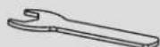
4 mm (x1)

5 mm (x1)


M10 (x1)
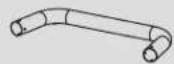
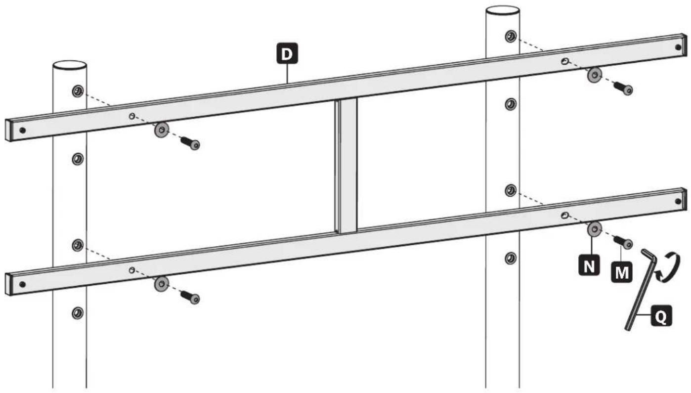
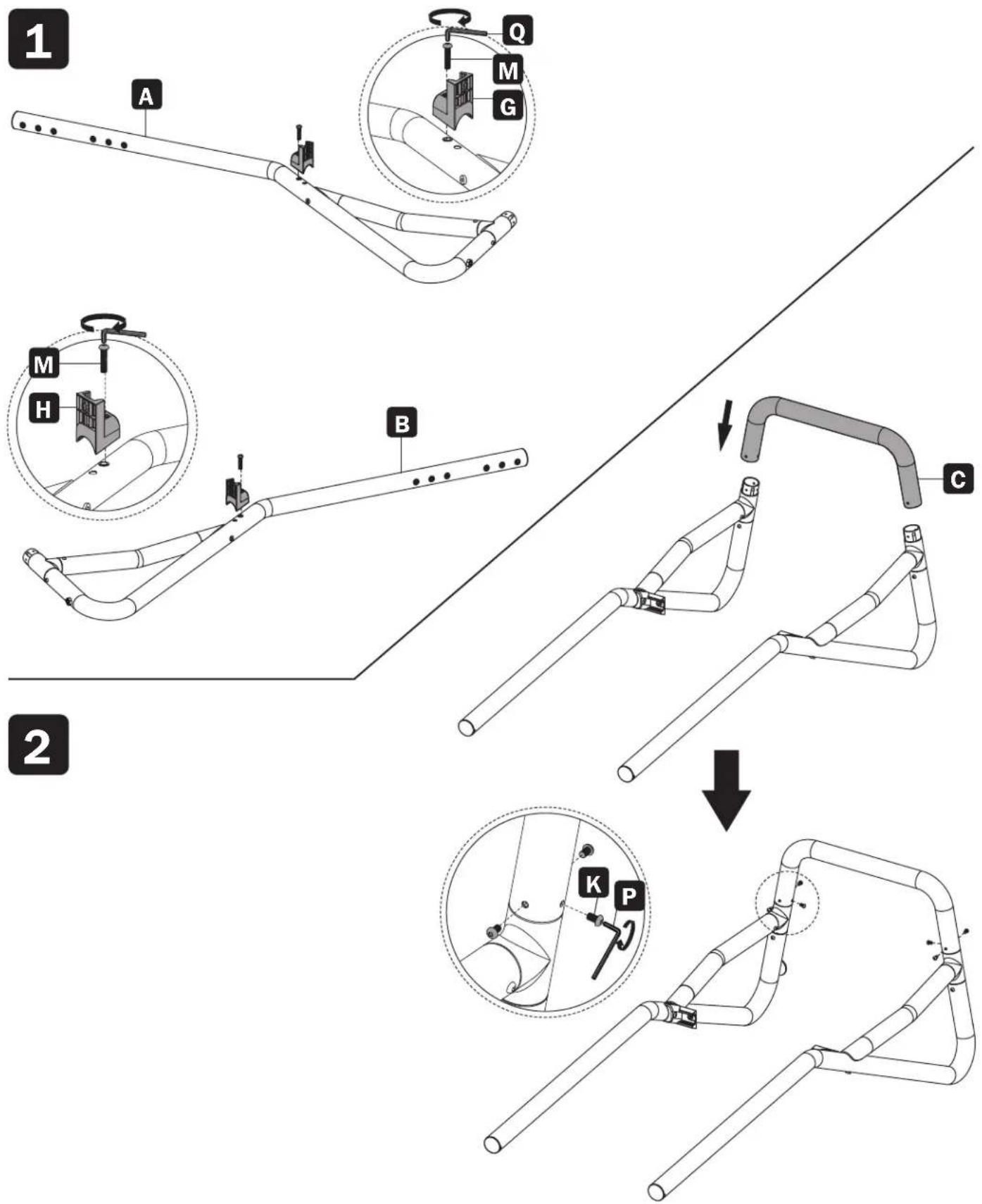
Assembly
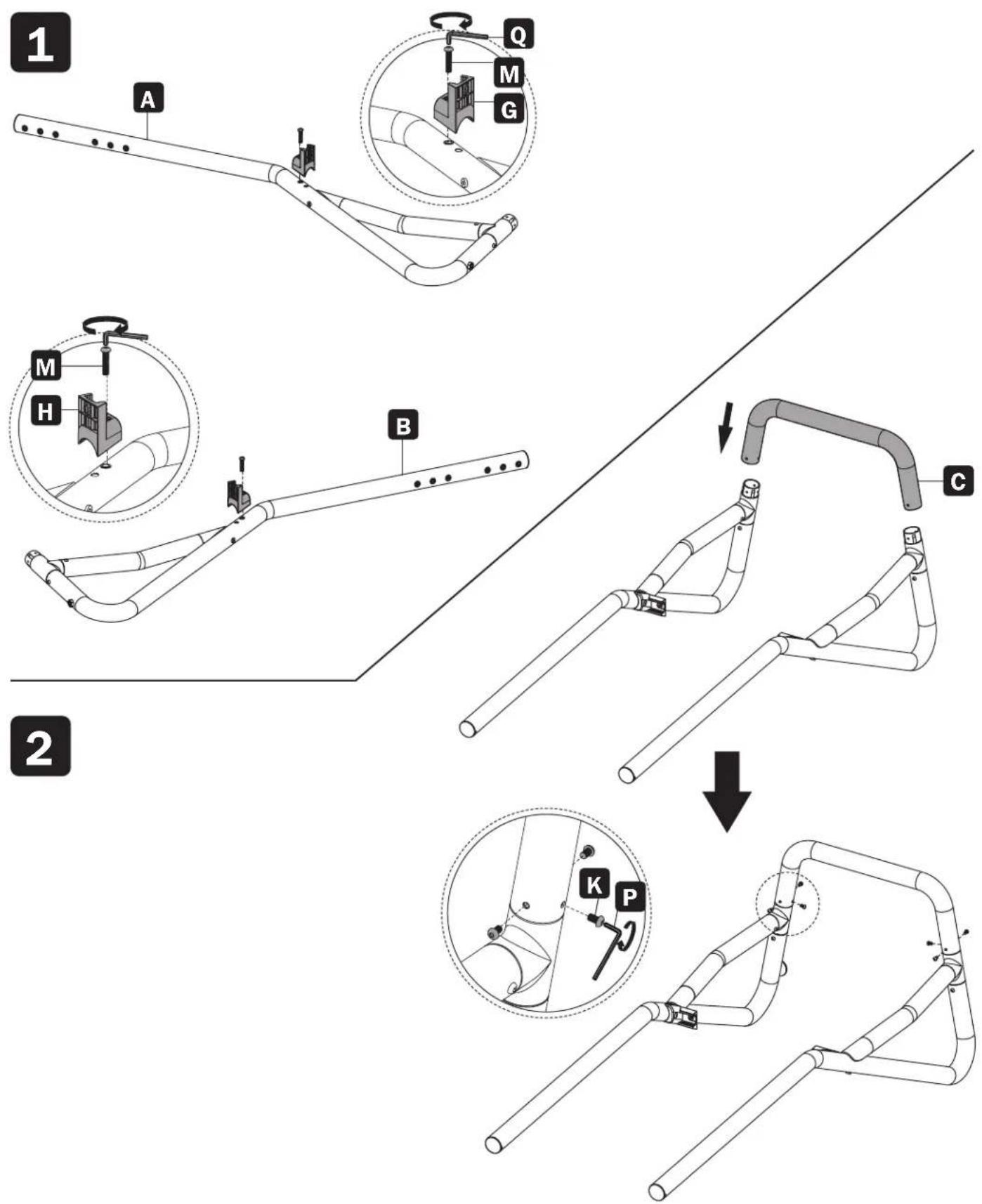
Assembly
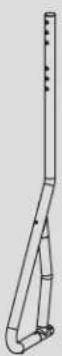
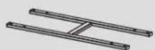
3a
For Use as a Fixed Stand
natural_image
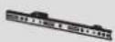
Technical line drawing of a mechanical linkage or support structure with multiple pipes and mounting points (no text or symbols)3b
For Use as a Mobile Cart
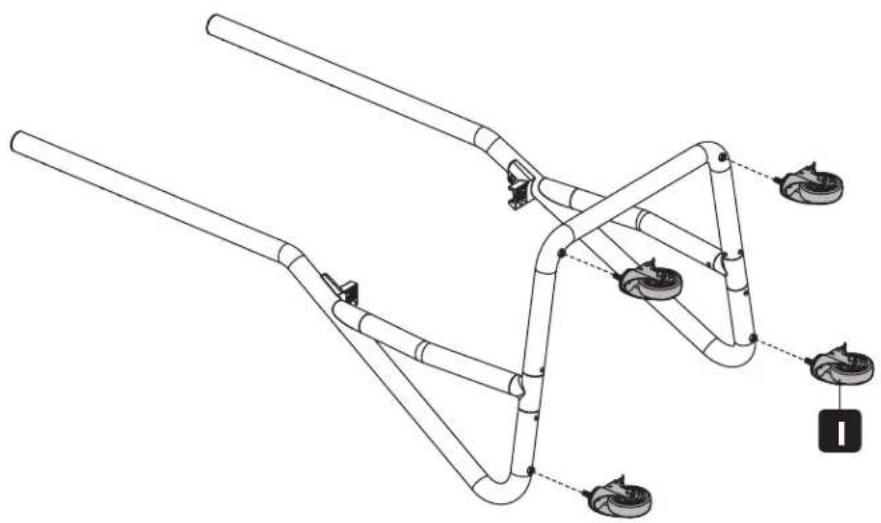
natural_image
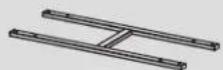
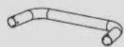
Technical line drawing of a mechanical linkage system with multiple components and mounting points (no text or symbols)Install the heavy-duty locking casters into the threaded caster slots. Use the wrench R to tighten the casters.
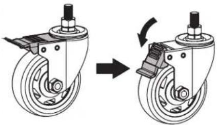
natural_image
Mechanical diagram showing a wheel assembly before and after rotation, with no text or symbols present.Assembly
4

Assembly
5
Assembly

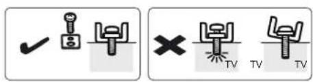

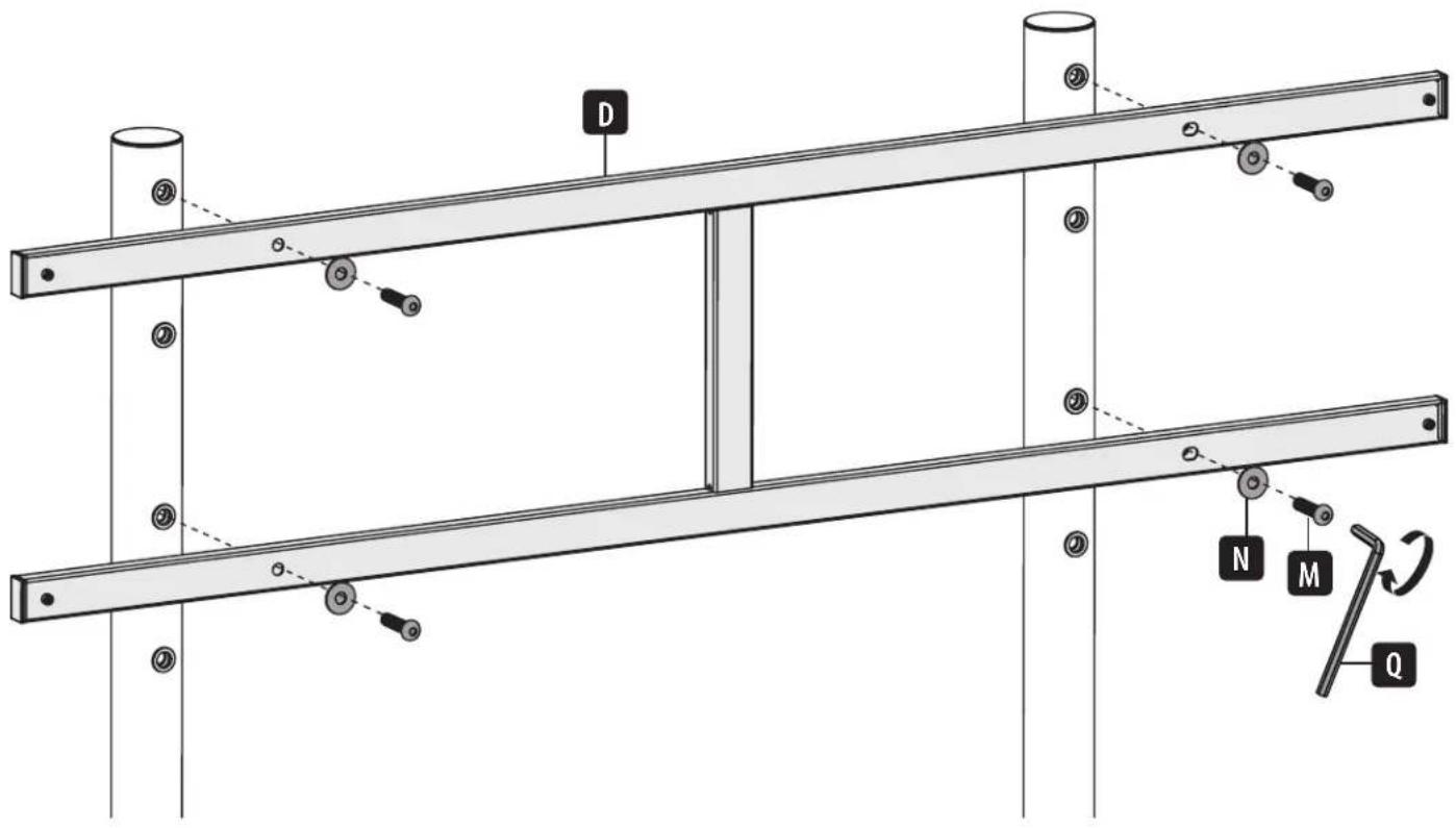
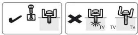
For Flat-Back Screens
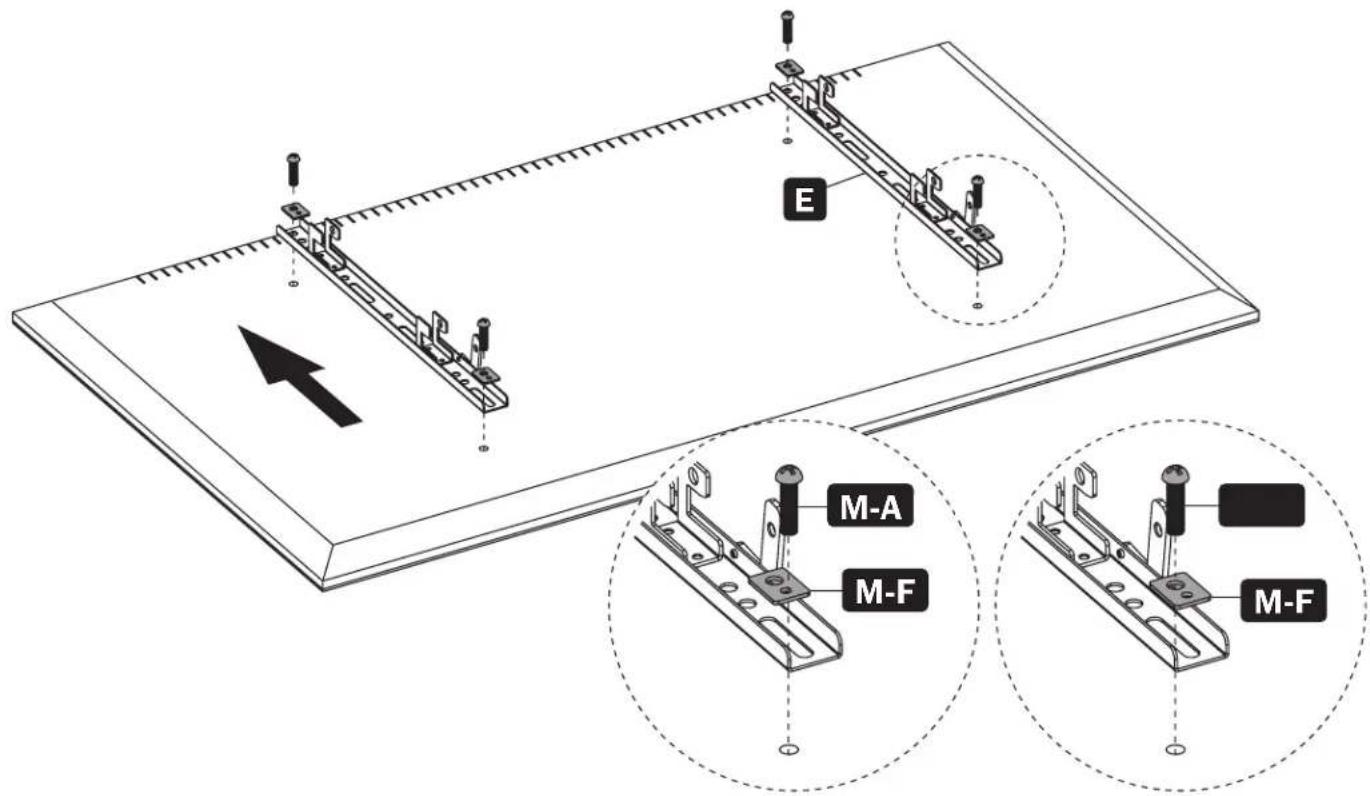
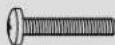
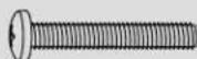
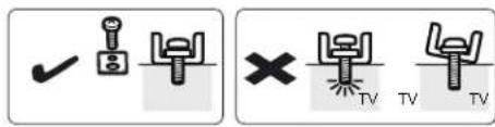
Note: Choose the appropriate Screws, Washers and Spacers (if needed) according to the type of screen.

CAUTION:
Do not over-tighten screws.
Assembly
6b
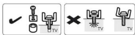

For Recessed-Back Screens or Accessing A/V Inputs
Note: Choose the appropriate Screws, Washers and Spacers (if needed) according to the type of screen.

CAUTION:
Do not over-tighten screws.
Assembly
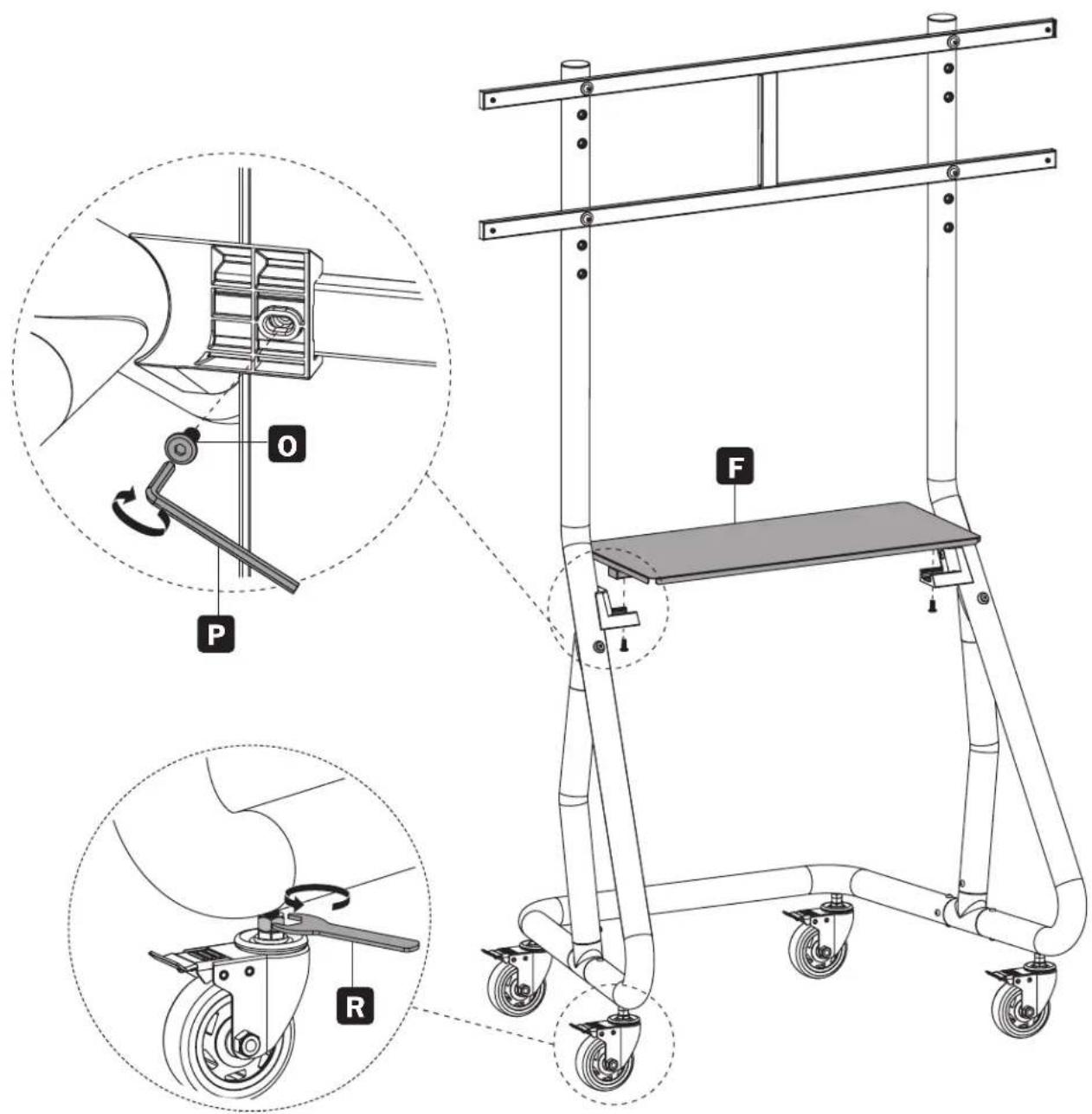
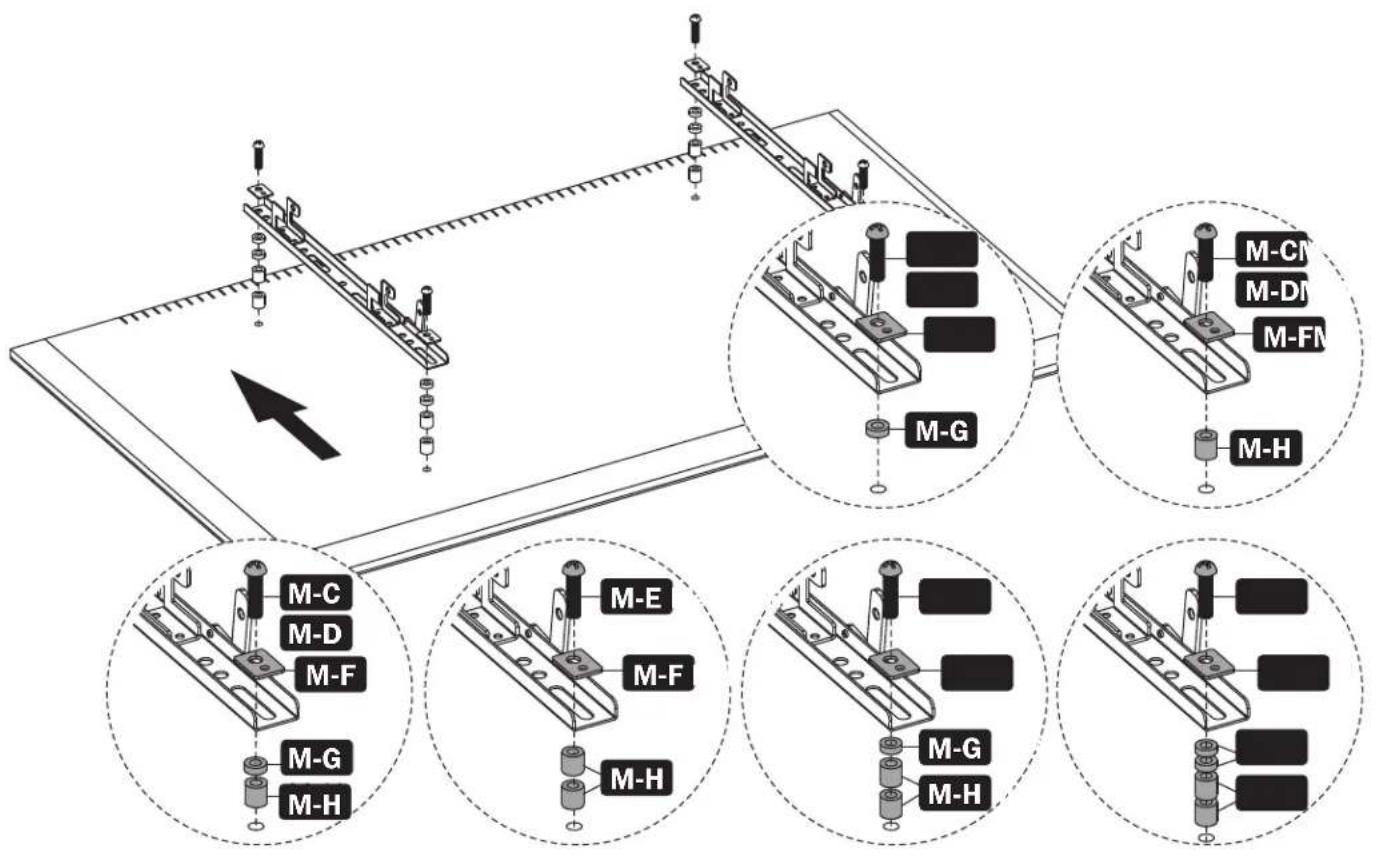
7

Note: With the help of an assistant or mechanical lifting equipment, hook the mounting arms onto the mounting brackets.

CAUTION:
Make sure the display is correctly mounted before releasing the display.
Assembly
8
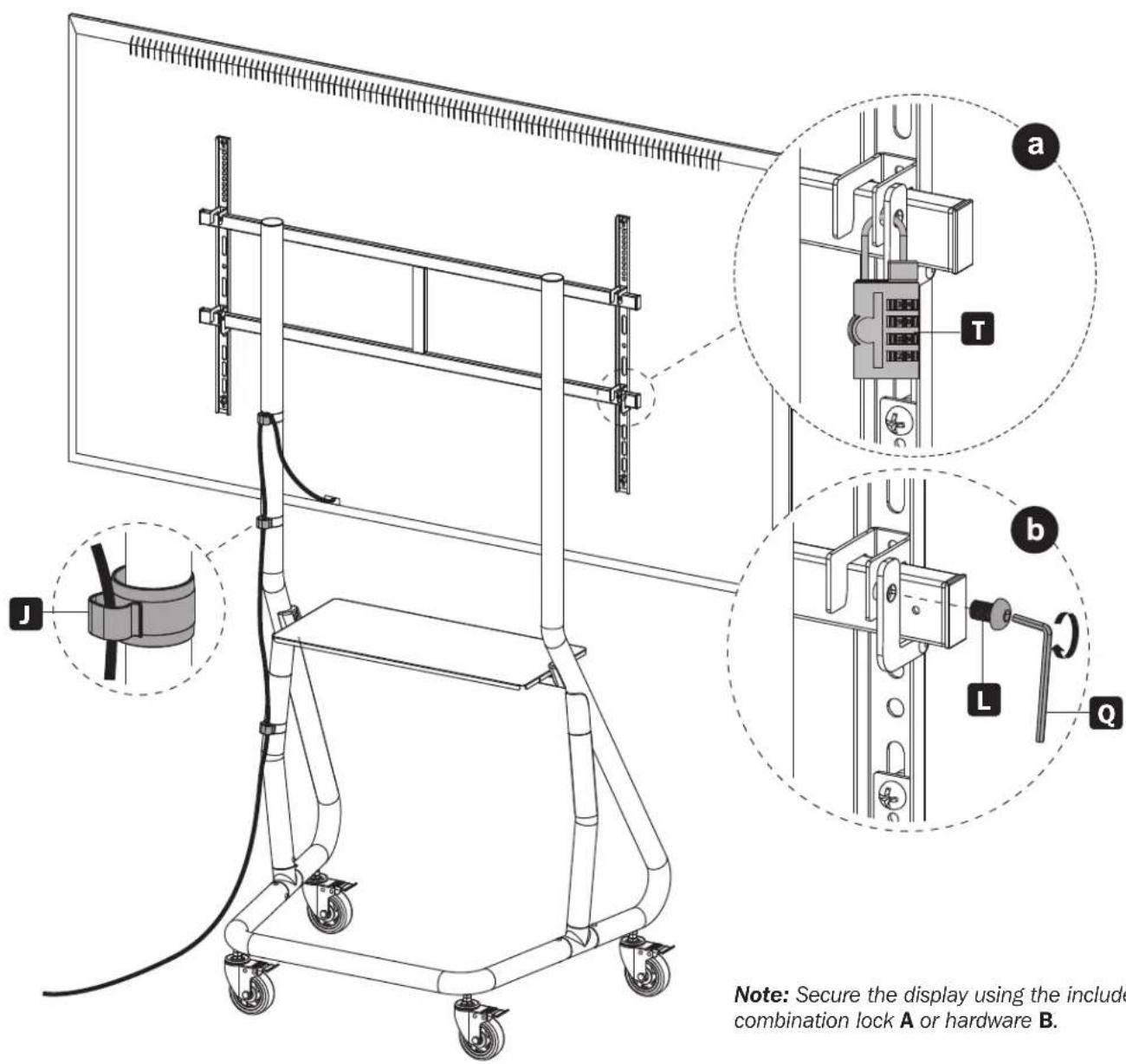
Note: Secure the display using the included combination lock A or hardware B.
Maintenance
- Check that the bracket is secure and safe to use at regular intervals (at least every three months).
- Please visit tripplite.com/support if you have any questions.


1111 W. 35th Street, Chicago, IL 60609 USA • tripplite.com/support
natural_image
Line drawing of a mechanical lift or cart with wheels and vertical supports (no text or symbols)English 1 • Français 25 • Русский 37 • Deutsch 49

natural_image
Line drawing of two vertical metal supports with evenly spaced notches (no text or symbols)A
(x1)
B
(x1)

C
(x1)

D
(x1)
E
(x2)

F
(x1)

G
(x1)

H
(x1)

I
(x4)

J
(x3)

S
(x4)

T
(x1)
Paquete M

M-A
M5x14 (x4)

M-B
M6x14 (x4)

M-C
M6x30 (x4)

M-D
M8x30 (x4)

M-E
M8x50 (x4)

M-F
(x4)

M-G
(x8)

M-H
(x8)
Paquete P


M6x10 (x6)


M8x15 (x1)


M8x35 (x6)


D8 (x4)


M6x16 (x2)


4 mm (x1)


5 mm (x1)

M10 (x1)
Ensamble

3a
natural_image
Technical line drawing of a mechanical linkage or support structure with multiple pipes and mounting points (no text or symbols)3b
natural_image
Technical line drawing of a mechanical linkage system with multiple joints and linkages (no text or symbols)natural_image
Mechanical diagram showing a wheel assembly before and after rotation, with no text or symbols present.Ensamble
4
Ensamble
5

Ensamble


natural_image
Line drawing of a mechanical lift or support structure with wheels and vertical supports (no text or symbols)English 1 • Español 13 • Русский 37 • Deutsch 49

MISE EN GARDE : NE PAS EXCÉDER LA CAPACITÉ PONDÉRALE MAXIMUM INDIQUÉE. CELA RISQUERAIT DE CAUSER DES BLESSURES GRAVES OU DES DOMMAGES MATÉRIELS!

400 x 400/600 x 400 800 x 400/800 x 600 1000 x 600


1111 W. 35th Street, Chicago, IL 60609 USA • tripplite.com/support
natural_image
Line drawing of two vertical metal supports with evenly spaced notches (no text or symbols)A
(x1)

B
(x1)

C
(x1)

D
(x1)

E
(x2)

F
(x1)

G
(x1)

H
(x1)

I
(x4)

J
(x3)

S
(x4)

T
(x1)
Emballage M

M-A
M5x14 (x4)

M-B
M6 x 14 (x4)
M-C
M6x30 (x4)

M-D
M8x30 (x4)

M-E
M8x50 (x4)

M-F
(x4)

M-G
(x8)

M-H
(x8)
Emballage P


M6x10 (x6)


M8x15 (x1)


M8x35 (x6)


D8 (x4)


M6x16 (x2)

4 mm (x1)


5 mm (x1)


M10 (x1)
Assemblage

3a
natural_image
Technical line drawing of a mechanical linkage or support structure with multiple pipes and mounting feet (no text or symbols)3b
natural_image
Technical line drawing of a mechanical linkage system with multiple components and mounting points (no text or symbols)natural_image
Mechanical diagram showing a two-step transformation of a wheel with stator and rotor (no text or symbols)Assemblage
4

Assemblage
5

Assemblage


1111 W. 35th Street, Chicago, IL 60609 USA • tripplite.com/support
natural_image
Technical line drawing of a mechanical lift or support structure with wheels and vertical supports (no text or symbols)English 1 • Español 13 • Français 25 • Deutsch 49

1111 W. 35th Street, Chicago, IL 60609 USA - tripplite.com/support
natural_image
Technical line drawing of two vertical mechanical arms with mounting feet (no text or symbols)A
1 шт.

B
1 шт.
C
1 шт.
D
1 шт.
E
2 шт.

F
1 шт.

G
1 шт.

H
1 шт.

I
4 шт.

J
3 шт.

S
4шт.

T
1 шт.
3a
natural_image
Technical line drawing of a mechanical linkage or support structure with multiple pipes and mounting points (no text or symbols)3b
natural_image
Technical line drawing of a mechanical linkage system with multiple rods and pulleys (no text or symbols)natural_image
Mechanical diagram showing a wheel assembly before and after rotation, with no text or symbols present.Порядок сборки
4
5

Порядок сборки
6a


natural_image
Line drawing of a mechanical lift or support structure with wheels and vertical supports (no text or symbols)English 1 • Español 13 • Français 25 • Русский 37

Manufacturing Excellence.
1111 W. 35th Street, Chicago, IL 60609 USA • tripplite.com/support
natural_image
Line drawing of two vertical metal supports with evenly spaced notches (no text or symbols)A
(x1)

B
(x1)

C
(x1)

D
(x1)

E
(x2)

F
(x1)

G
(x1)

H
(x1)

I
(x4)

J
(x3)

S
(x4)

T
(x1)
Paket M

M-A
M5x14 (x4)

M-B
M6x14 (x4)
M-C
M6x30 (x4)

M-D
M8x30 (x4)
M-E
M8x50 (x4)

M-F
(x4)

M-G
(x8)

M-H
(x8)
Paket P


M6x10 (x6)


M8x15 (x1)


M8x35 (x6)


D8 (x4)


M6x16 (x2)

4 mm (x1)

5 mm (x1)


M10 (x1)
Montage
3a
natural_image
Technical line drawing of a mechanical linkage or support structure with multiple pipes and mounting points (no text or symbols)3b
natural_image
Technical line drawing of a mechanical linkage system with no visible text or symbolsnatural_image
Mechanical diagram showing a two-step transformation of a wheel with stator and rotor (no text or symbols)Montage
4

Montage
5

Montage


1111 W. 35th Street, Chicago, IL 60609 USA • tripplite.com/support