B1261A0U - HDMI Extender Tripp Lite - Free user manual and instructions
Find the device manual for free B1261A0U Tripp Lite in PDF.

| Product Type | HDMI Extender over Cat5e/6 |
| Brand | Tripp Lite |
| Model | B1261A0U (B126-1A0-U) |
| Source Compatibility | HDMI, resolution up to 1920x1080 (1080p) or 4K depending on distance |
| Maximum Distance | Up to 100 m with Cat6 cable for 1080p |
| Power Supply | Via USB Micro-B port (5 V, 1 A); optional power adapter |
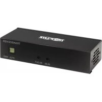
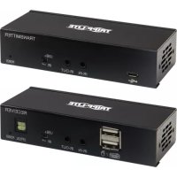
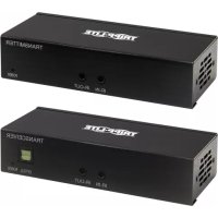
| Transmitter Connectors | 1 HDMI input, 1 RJ45 output |
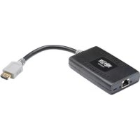
| Receiver Connectors | 1 RJ45 input, 1 built-in HDMI output (fixed cable) |
| Recommended Cable | Cat5e or Cat6 solid conductor cable (0.51 mm) |
| Equalization Adjustment | Yes, on the receiver to compensate for distance |
| LED Indicators | Green (power) and orange (source signal) on transmitter and receiver |
| Typical Power Consumption | 2.5 W (max 5 W) |
| Operating Temperature | 0 °C to 40 °C |
| Relative Humidity | 5% to 85% (non-condensing) |
| Housing Material | ABS plastic |
| Transmitter Dimensions (L x W x H) | 2.5 x 1.5 x 0.8 cm (estimated) |
| Receiver Dimensions (L x W x H) | 3.0 x 1.5 x 0.8 cm (estimated) |
| Unit Weight | 40 g (transmitter + receiver) |
| Kit Contents | Transmitter, receiver with built-in HDMI cable, USB Micro-B cable, quick guide |
| Warranty | 1 year (repair or replacement) |
| Certifications | FCC Class B, RoHS |
| Maintenance | Clean with a dry, non-abrasive cloth |
| Safety Precautions | Do not expose to moisture; use only standard cables |
| Repairability | No user-serviceable parts; contact support for replacement |
Frequently Asked Questions - B1261A0U Tripp Lite
User questions about B1261A0U Tripp Lite
0 question about this device. Answer the ones you know or ask your own.
Ask a new question about this device
Download the instructions for your HDMI Extender in PDF format for free! Find your manual B1261A0U - Tripp Lite and take your electronic device back in hand. On this page are published all the documents necessary for the use of your device. B1261A0U by Tripp Lite.
USER MANUAL B1261A0U Tripp Lite
may differ from image.
Espanol 11
Français 21
Deutsch 31
Italiano 41

Powering Business Worldwide
Product Features
- Extends a 1080p HDMI audio/video signal up to 125 ft. from the source
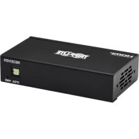
- B126-1A0-U works with a B126-002 or B126-004 extender/splitter transmitter unit
Additional HDMI port allows for the connection of a local monitor (B126-1A1-U only)
3D and HDCP compliant - Receiver units feature a built-in equalization control to adjust video image
- USB Micro-B ports supply power to the B126-1A1-U and B126-1A0-U; no external power supplies required
- HDMI connector with latches provides a more secure connection
Supports stereo audio - Compatible with all operating systems
- No software or drivers required
*For details on the B126-002 and/or B126-004, reference the owner's manual included with the unit. The manual can also be found at Triplite.Eaton.com.
Package Contents
- Transmitter* and Receiver units
USB Micro-B Cable(s) - 3 ft. - Screwdriver for Equalization adjustment
- Owner's Manual
*The B126-1A1-U comes with both Transmitter and Receiver units, as well as two USB Micro-B cables. The B126-1A0-U comes with a Receiver unit and one USB Micro-B cable.
2
Optional Accessories
N202-Series Cat6 24 AWG Solid Wire Patch Cables
P568-Series High Speed HDMI Cables
- UR05C-Series USB Micro-B Charge-Only Cables
U280-002-W12 2-Port USB Wall Charger
UAC-1B 1-Port USB Wall Charger
System Requirements
- Computer, Blu-ray™, or other source with an HDMI output port
- Display with an HDMI port
Extender Kit Installation
Note:
- Test to make sure the entire installation works properly before pulling cables through ceilings/walls.
- To achieve maximum distance and performance, 24 AWG solid wire Cat5e/6 cable must be used. The use of stranded wire Cat5e/6 cable or cable with a gauge size higher than 24 AWG will result in shorter extension distance. All N202-Series Cat6 cables are made with 24 AWG solid wire cabling.
- Make sure the power to all devices you are connecting is turned off prior to installation.
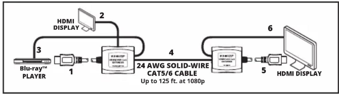
- Connect the built-in HDMI cable of the transmitter unit to the HDMI source.
- Optional: Connect an HDMI monitor to the LOCAL port on the B126-1A1-U transmitter using a P568-Series HDMI Cable.
- Connect the included USB Micro-B Cable between the transmitter unit and a USB port on the source or a USB wall outlet.
- Connect the RJ45 port on the transmitter to the RJ45 port on the receiver using Cat5e/6 cable.
Note: See the installation diagrams for maximum extension distance and video resolutions.
- Connect the built-in HDMI cable of the receiver unit to an HDMI monitor input port.
- Connect the included USB Micro-B cable between the receiver unit and a USB port on the display or a USB wall outlet.
- Turn on the power to the HDMI source and HDMI display. The green RJ45 LEDs on the transmitter and receiver units will illuminate to indicate they are receiving power. The orange RJ45 LEDs on the transmitter and receiver units will illuminate to indicate they are receiving a signal from the source.
- If necessary, adjust the Equalization control on the receiver unit to improve the video image.
Note: An improper Equalization setting can cause the monitor to display no picture at all. Try each Equalization setting until an acceptable image is displayed.
4
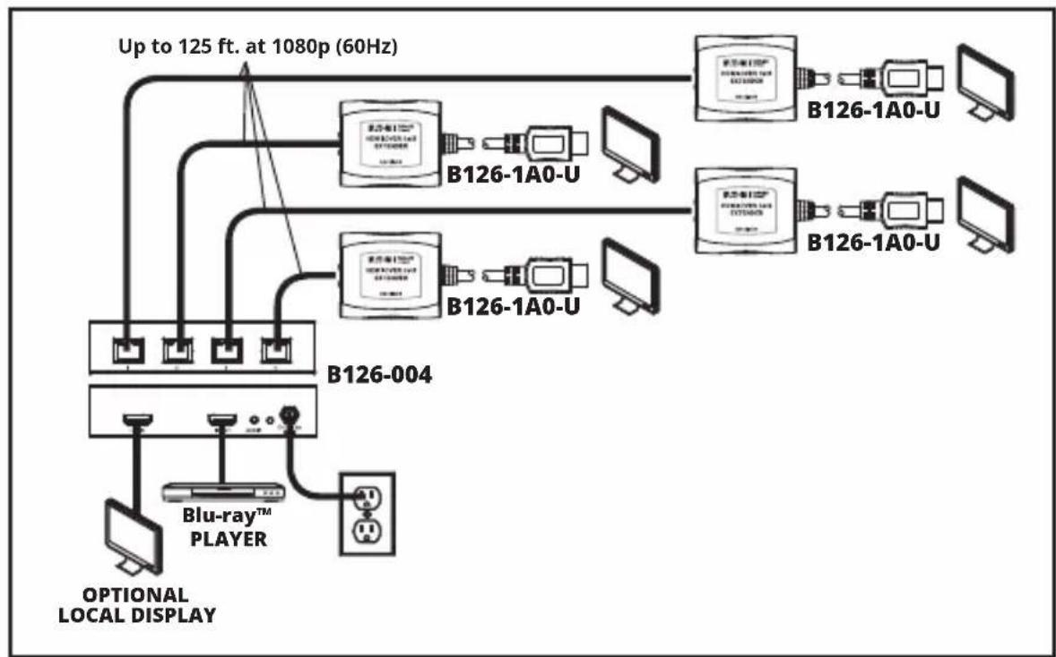
Extender/Splitter Installation
Notes:
- Test to make sure the entire installation works properly before pulling cables through ceilings/walls.
- To achieve maximum distance and performance, 24 AWG solid wire Cat5e/6 cable must be used. The use of stranded wire Cat5e/6 cable or cable with a gauge size higher than 24 AWG will result in shorter extension distance. All N202-Series Cat6 cables are made with 24 AWG solid wire cabling.
- Make sure the power to all devices you are connecting is turned off prior to installation.
- The installation diagram shows the B126-004 local transmitter unit. The B126-002 installation is the same, except there are only 2 remote ports and no local monitor port.
Extender/Splitter Installation
- Connect the HDMI source to the INPUT port on the B126-002 or B126-004 using a P568-Series HDMI Cable.
- Optional for B126-004: Connect an HDMI monitor to the LOCAL port on the B126-004 using a P568-Series HDMI Cable.
- Connect the external power supply to the transmitter unit and plug it into an Eaton Tripp Lite series Surge Protector, PDU or UPS. The green LED illuminates to indicate the unit is receiving power from the external power supply.
- Using Cat5e/6 cable, connect one of the RJ45 output ports on the transmitter unit to the RJ45 input port on the B126-1A0-U.
- Connect the B126-1A0-U to a monitor using its built-in HDMI Cable.
- Connect the included USB Micro-B cable to the port on the B126-1A0-U and a USB port on the display or a USB wall outlet. The green LED will illuminate, indicating the unit is receiving power from the USB Micro-B port.
- Repeat Steps 4-7 for each additional B126-1A0-U in the installation.
- Turn on the power to the HDMI source and HDMI displays. The orange RJ45 LEDs illuminate on both transmitter and receivers to indicate the unit is receiving a signal from the source. The screen should now be displayed on the connected monitors.
- If necessary, use the Equalization control on the B126-1A0-U to adjust the video image.
Note: An improper Equalization setting can cause the monitor to display no picture at all. Try each Equalization setting until an acceptable picture is displayed.
Troubleshooting
If you are unable to get an acceptable image after following the installation instructions, try the troubleshooting tips below.
- Is the USB Micro-B cable that came with the product connected and plugged into a working power source? For the product to function properly, the transmitter and receiver must be connected to and receiving power from the USB Micro-B cable.
- Was the power to the HDMI source turned off prior to installation? If not, restart.
- What resolution are you trying to reach? See the Product Features and Installation sections in this manual for details on maximum distance and resolution. The shorter the extension distance, the higher the resolution you will be able to obtain. If you are not able to get an acceptable image, try lowering your computer's video resolution or adjusting the refresh rate.
- What type of cabling are you using? Inferior cabling can result in poor performance, so it is important that you use cables that can support the video resolution you are trying to obtain. To achieve maximum distance and resolution, 24 AWG solid-wire UTP cable (such as N202-Series cables) must be used.
- Test your cables to ensure they are working properly. For example, connect your Cat5e/6 cable between a computer and a network to verify that it establishes a network connection.
- Do you have any patch panels or other devices in between the transmitter and receiver units? The HDMI over Cat5 extender kits were designed to be connected directly from the transmitter to the receiver via UTP cable. The more connection points between the source and the remote monitor, the more likely signal degradation will occur, causing poor performance. If you have a patch panel or other device in between, it should be removed from the installation.
- Do you have a splitter, switch or other device in between the computer and transmitter, or in between the receiver and display? The HDMI over Cat5 extender kits were designed for the transmitter to connect directly with the source computer, and for the receiver to connect directly to the display. If you have a splitter, switch, or other device in between, it should be removed from the installation.
Troubleshooting
- Check your cabling for any damage that may have occurred during installation. If a cable connector is loosened from being pulled through ceilings/walls, or the cable jacket is damaged, causing the wiring to be exposed, you will not be able to achieve maximum performance.
- Are the transmitter and/or receiver units located in an area that exposes them to elevated temperatures? If the product is overheating, it will not function properly.
Warranty and Product Registration
1-Year Limited Warranty
We warrant our products to be free from defects in materials and workmanship for a period of one (1) year from the date of initial purchase. Our obligation under this warranty is limited to repairing or replacing (at its sole option) any such defective products. Visit Tripplite.Eaton.com/support/product-returns before sending any equipment back for repair. This warranty does not apply to equipment which has been damaged by accident, negligence or misapplication or has been altered or modified in any way.
EXCEPT AS PROVIDED HEREIN, WE MAKE NO WARRANTYES, EXPRESS OR IMPLIED, INCLUDING WARRANTY OF MERCHANTABILITY AND FITNESS FOR A PARTICULAR PURPOSE. Some states do not permit limitation or exclusion of implied warranties; therefore, the aforesaid limitation(s) or exclusion(s) may not apply to the purchaser.
EXCEPT AS PROVIDED ABOVE, IN NO EVENT WILL WE BE LIABLE FOR DIRECT, INDIRECT, SPECIAL, INCIDENTAL OR CONSEQUENTIAL DAMAGES ARISING OUT OF THE USE OF THIS PRODUCT, EVEN IF ADVISED OF THE POSSIBILITY OF SUCH DAMAGE. Specifically, we are not liable for any costs, such as lost profits or revenue, loss of equipment, loss of use of equipment, loss of software, loss of data, costs of substitutes, claims by third parties, or otherwise.
Warranty and Product Registration
FCC Notice, Class B
This device complies with part 15 of the FCC Rules. Operation is subject to the following two conditions: (1) This device may not cause harmful interference, and (2) this device must accept any interference received, including interference that may cause undesired operation.
Note: This equipment has been tested and found to comply with the limits for a Class B digital device, pursuant to part 15 of the FCC Rules. These limits are designed to provide reasonable protection against harmful interference in a residential installation. This equipment generates, uses and can radiate radio frequency energy and, if not installed and used in accordance with the instructions, may cause harmful interference to radio communications. However, there is no guarantee that interference will not occur in a particular installation. If this equipment does cause harmful interference to radio or television reception, which can be determined by turning the equipment off and on, the user is encouraged to try to correct the interference by one or more of the following measures:
Reorient or relocate the receiving antenna.
- Increase the separation between the equipment and receiver.
- Connect the equipment into an outlet on a circuit different from that to which the receiver is connected.
Consult the dealer or an experienced radio/TV technician for help.
Any changes or modifications to this equipment not expressly approved by Eaton could void the user's authority to operate this equipment.
Warranty and Product Registration
WEEE Compliance Information for Customers and Recyclers (European Union)
Under the Waste Electrical and Electronic Equipment (WEEE) Directive and implementing regulations, when customers buy new electrical and electronic equipment from Eaton, they are entitled to:
- Send old equipment for recycling on a one-for-one, like-for-like basis (this varies depending on the country)
- Send the new equipment back for recycling when this ultimately becomes waste
Use of this equipment in life support applications where failure of this equipment can reasonably be expected to cause the failure of the life support equipment or to significantly affect its safety or effectiveness is not recommended.
Eaton has a policy of continuous improvement. Specifications are subject to change without notice.
EAT·N
Powering Business Worldwide
Eaton
1000 Eaton Boulevard
Cleveland, OH 44122
United States
Eaton.com
© 2023 Eaton
All Rights Reserved
Publication No. 23-09-016 /
93-34F6_RevD
September 2023
Eaton is a registered trademark.
All trademarks are property of their respective owners.
10
Powering Business Worldwide
*The B126-1A1-U comes with both Transmitter and Receiver units, as well as two USB Micro-B cables. The B126-1A0-U comes with a Receiver unit and one USB Micro-B cable.
Note: An improper Equalization setting can cause the monitor to display no picture at all. Try each Equalization setting until an acceptable image is displayed.
Instalacion del Extensor / Divisor
Notas:
Powering Business Worldwide
Eaton
1000 Eaton Boulevard
Cleveland, OH 44122
Estados Unidos
Eaton.com
© 2023 Eaton
Powering Business Worldwide
Eaton
1000 Eaton Boulevard
Cleveland, OH 44122
États-Unis
Eaton.com
Powering Business Worldwide
Produktmerkmaler utilizzato il cavo HDMI integrato
6. Si colleghi il cavo USB Micro-B in dotazione alla porta del B126-1A0-U e a una porta USB del display o a una presa USB a muro. il LED verde si accende,indicando che l'unità sta ricevendo l'alimentazione alla porta USB Micro-B
7. Si ripetano i passaggi 4-7 per agli altri B126-1A0-U nelle'installazione
8. Si accendano la sorgente HDMI e gli schermi HDMI, i LED RJ45 arancioni si accendono sua sul trasmettitore che sul ricevitore perindicare che l'unità sta ricevendo un segnale alla sorgente, la schermata dovrebbe ora apparire sui monitor collegati
9. Se necessario, si utilizzii il controllo di equalizzazione del B126-1A0-U per regolare l'imagine video
N.B.: Un'impostazione errata dell'equalizzazione potrebbe causare l'assenza di immagini sul monitor. Si provi agli impostazione di equalizzazione sono a vedere un'immagine accettabile.
- Verlangert ein 1080p-HDMI-Audio-/Videosignal auf bis zu 38 m von der Quelle entfernt
B126-1A0-U Funktioniert mit einer Extender-/Splitter-Sendereinheit B126-002* oder B126-004*
- Zusätzlicher HDMI-Anschluss ermittelicht den Anschluss eines lokalen Monitors (nur B126-1A1-U)
3D- und HDCP-kompatibel
- Empfängereinheiten verfügbar über eine integrierte Entzerrungssteuerung zur Anpassung des Videobildes
- USB-Micro-B-Anschlüsse versorgen B126-1A1-U und B126-1A0-U mit Strom; keine externen Netzele erforderlich
- HDMI-Anschluss mit Riegeln sorgt für eine sichere Verbindung
- Unterstützt Stereo-Audio
- Kompatibel mit allen Betriebssystemen
Keine Software oder Treiber erforderlich
- Verlangert ein 1080p-HDMI-Audio-/Videosignal auf bis zu 38 m von der Quelle entfernt
B126-1A0-U Funktioniert mit einer Extender-/Splitter-Sendereinheit B126-002* oder B126-004* - Zusätzlicher HDMI-Anschluss ermittelicht den Anschluss eines lokalen Monitors (nur B126-1A1-U)
3D- und HDCP-kompatibel - Empfängereinheiten verfügbar über eine integrierte Entzerrungssteuerung zur Anpassung des Videobildes
- USB-Micro-B-Anschlüsse versorgen B126-1A1-U und B126-1A0-U mit Strom; keine externen Netzele erforderlich
- HDMI-Anschluss mit Riegeln sorgt für eine sichere Verbindung
- Unterstützt Stereo-Audio
- Kompatibel mit allen Betriebssystemen
Keine Software oder Treiber erforderlich
Powering Business Worldwide
Eaton
1000 Eaton Boulevard
Cleveland, OH 44122
Vereinigte Staaten
Eaton.com
© 2023 Eaton
Powering Business Worldwide
Eaton
1000 Eaton Boulevard
Cleveland, OH 44122
Stati Uniti
Eaton.com
© 2023 Eaton