SmartRack SRWO12US2 - Server Tripp Lite - Free user manual and instructions
Find the device manual for free SmartRack SRWO12US2 Tripp Lite in PDF.

User questions about SmartRack SRWO12US2 Tripp Lite
0 question about this device. Answer the ones you know or ask your own.
Ask a new question about this device
Download the instructions for your Server in PDF format for free! Find your manual SmartRack SRWO12US2 - Tripp Lite and take your electronic device back in hand. On this page are published all the documents necessary for the use of your device. SmartRack SRWO12US2 by Tripp Lite.
USER MANUAL SmartRack SRWO12US2 Tripp Lite
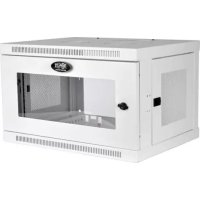
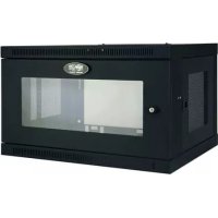
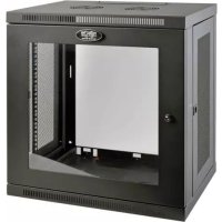
Hinged Open Frame Wall-Mount Server Rack
Models: SRW012US2, SRW016US

natural_image
Technical line drawing of a mechanical frame assembly (no text or symbols)Español 7 • Français 13
WARRANTY REGISTRATION
Register your product today and be automatically entered to win an ISOBAR ^® surge protector in our monthly drawing!
tripplite.com/warranty


text_image
TRIPP·LITE
1111 W. 35th Street, Chicago, IL 60609 USA • tripplite.com/support
Copyright © 2021 Tripp Lite. All rights reserved.
Introduction
Tripp Lite's SRWO12US2 and SRWO16US are perfect open frame rack solutions for applications where space is limited. Heavy-duty construction and a wall-mount form factor keep equipment out of the way. The swinging door enables easy access to rack-mounted equipment. The SRWO12US2 and SRWO16US accommodate all standard 19-inch rack-mount equipment, up to 22 inches deep.
Important Safety Instructions

SAVE THESE INSTRUCTIONS
This manual contains instructions and warnings that must be followed during the installation and operation of the product described in this manual. Failure to comply may invalidate the warranty and cause property damage or personal injury.
- Keep the rack in a controlled indoor environment, away from moisture, temperature extremes, flammable liquids and gasses, conductive contaminants and dust.
- Leave adequate space at the front of the rack for proper ventilation.
- Inspect the shipping container and the rack for shipping damage. Do not use the rack if it is damaged.
- Leave the rack in the shipping container until it has been moved as close to the final installation location as possible.
- Install the rack in a structurally sound area capable of handling the load, the weight of the rack, all equipment that will be installed in the rack and any other equipment that will be installed nearby.
- Save all packing materials for later use. Repacking and shipping the enclosure without the original packing materials may cause product damage that may affect the warranty.
- Do not attempt to install the rack unassisted.
- Be sure to use four screws to secure the rack to a 16" on center stud wall using 5/16" minimum diameter lag bolts.
- Never secure the rack to plaster board alone. Always use the studs for these types of walls.
- Be sure to always have one side of the door latched when opening. Failure to do this will cause your equipment to fall out.
- Installation is to be performed by a SKILLED PERSON knowledgeable in mounting cabinets to surfaces intended to be used in the end use application. It is the installer's responsibility to choose appropriate hardware to mount the cabinet to a desired surface and be sufficient to support the rated maximum load of 150 lbs.
• Install frame on wall using a level before placing the door on the frame rack. - Do not attempt to install equipment without first wall-mounting and stabilizing the rack.
- Use of this equipment in life support applications where failure of this equipment can reasonably be expected to cause the failure of the life support equipment or to significantly affect its safety or effectiveness is not recommended.
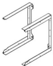
Parts List
natural_image
Technical line drawing of a mechanical bracket assembly (no text or symbols)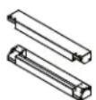
Wall-Mount Brackets (x2) Front Rail Assembly (x2) Swinging Door Assembly Hex Bolts (x16)
Installation/Wall-Mounting

WARNING: Do not attempt to mount the rack to the wall with equipment mounted to the rack.
WARNING: The wall surface, the wall studs and all user-supplied mounting hardware must be able to support the combined weight of the rack and all equipment that will be installed in the rack.
The rack can support an equipment load up to 150 lb. maximum, evenly distributed.
Important: Install the frame to the wall before placing the door on the frame rack.
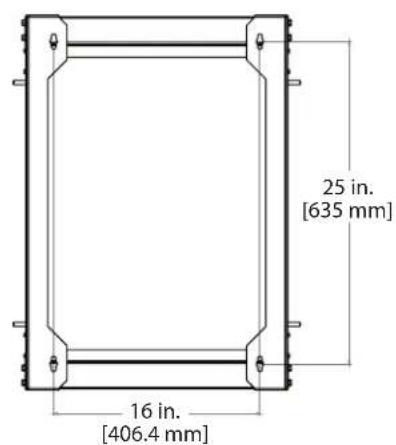
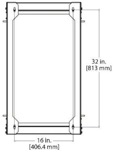
1 Drill holes in the supporting surface per the mounting hole diagram below.
text_image
25 in. [635 mm] 16 in. [406.4 mm]12U Cabinet Mounting Hole Pattern
text_image
32 in. [813 mm] 16 in. [406.4 mm]16U Cabinet Mounting Hole Pattern
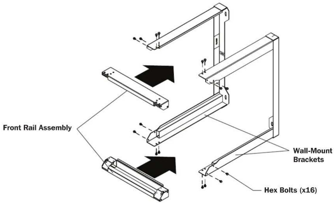
2 Assemble the front mounting rails to the wall-mount brackets using the included hex bolts.
text_image
Front Rail Assembly Wall-Mount Brackets Hex Bolts (x16)Installation/Wall-Mounting
3 Install wall-mount brackets onto the support surface using lag bolts (not included).

text_image
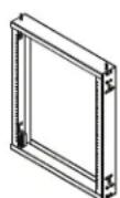
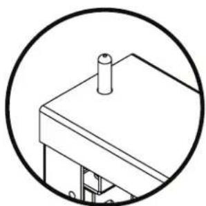
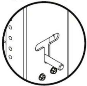
Lag Bolts (Not Included)4 Install the swinging door by pushing the spring-loaded hinge pins against the ramps on the front mounting rails.
natural_image
Simple line drawing of a mechanical assembly inside a circle (no text or symbols)Hinge pins are built into both sides of the top and bottom of the door to enable mounting the hinge to the right or the left.
The slot can be used to keep the hinge pin in the open position.
natural_image
Simple line drawing of a mechanical component inside a circular frame (no text or symbols)
text_image
Technical diagram of a structural frame assembly with labeled components A and B, showing structural elements and mounting points.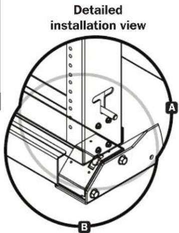
text_image
Detailed installation view A BEquipment Installation
The SRW012US2 and the SRW016US each support an equipment load up to 150 lb. maximum.
For all other equipment mounting, please refer to the intended equipment's Owner's Manual for installation instructions. Typically, this information can be found in the "Mounting" or "Rack Mounting" sections of the manual.
Storage and Service
Storage
The enclosure should be stored in a controlled indoor environment, away from moisture, temperature extremes, flammable liquids and gasses, conductive contaminants, dust and direct sunlight. Store the enclosure in its original shipping container if possible.
Service
Your Tripp Lite product is covered by the warranty described in this manual. A variety of Extended Warranty and On-Site Service Programs are also available from Tripp Lite. For more information on service, visit triplite.com/support. Before returning your product for service, follow these steps:
- Review the installation and operation procedures in this manual to ensure that the service problem does not originate from a misreading of the instructions.
- If the problem continues, do not contact or return the product to the dealer. Instead, visit triplite.com/support.
- If the problem requires service, visit tripplite.com/support and click the Product Returns link. From here you can request a Returned Material Authorization (RMA) number, which is required for service. This simple on-line form will ask for your unit's model and serial numbers, along with other general purchaser information. The RMA number, along with shipping instructions will be emailed to you. Any damages (direct, indirect, special or consequential) to the product incurred during shipment to Tripp Lite or an authorized Tripp Lite service center is not covered under warranty. Products shipped to Tripp Lite or an authorized Tripp Lite service center must have transportation charges prepaid. Mark the RMA number on the outside of the package. If the product is within its warranty period, enclose a copy of your sales receipt. Return the product for service using an insured carrier to the address given to you when you request the RMA.
Warranty and Product Registration
5-YEAR LIMITED WARRANTY
TRIPP LITE warrants its products to be free from defects in materials and workmanship for a period of five (5) years from the date of initial purchase. TRIPP LITE's obligation under this warranty is limited to repairing or replacing (at its sole option) any such defective products. To obtain service under this warranty, you must obtain a Returned Material Authorization (RMA) number from TRIPP LITE or an authorized TRIPP LITE service center. Products must be returned to TRIPP LITE or an authorized TRIPP LITE service center with transportation charges prepaid and must be accompanied by a brief description of the problem encountered and proof of date and place of purchase. This warranty does not apply to equipment, which has been damaged by accident, negligence or misapplication or has been altered or modified in any way.
EXCEPT AS PROVIDED HEREIN, TRIPP LITE MAKES NO WARRANTIES, EXPRESS OR IMPLIED, INCLUDING WARRANTIES OF MERCHANTABILITY AND FITNESS FOR A PARTICULAR PURPOSE.
Some states do not permit limitation or exclusion of implied warranties; therefore, the aforesaid limitation(s) or exclusion(s) may not apply to the purchaser.
EXCEPT AS PROVIDED ABOVE, IN NO EVENT WILL TRIPP LITE BE LIABLE FOR DIRECT, INDIRECT, SPECIAL, INCIDENTAL OR CONSEQUENTIAL DAMAGES ARISING OUT OF THE USE OF THIS PRODUCT, EVEN IF ADVISED OF THE POSSIBILITY OF SUCH DAMAGE. Specifically, TRIPP LITE is not liable for any costs, such as lost profits or revenue, loss of equipment, loss of use of equipment, loss of software, loss of data, costs of substitutes, claims by third parties, or otherwise.
Product Registration
Visit tripplite.com/warranty today to register your new Tripp Lite product. You'll be automatically entered into a drawing for a chance to win a FREE Tripp Lite product!*
* No purchase necessary. Void where prohibited. Some restrictions apply. See website for details.
WEEE Compliance Information for Tripp Lite Customers and Recyclers (European Union)

Under the Waste Electrical and Electronic Equipment (WEEE) Directive and implementing regulations, when customers buy new electrical and electronic equipment from Tripp Lite they are entitled to:
- Send old equipment for recycling on a one-on-one, like-for-like basis (this varies depending on the country)
- Send the new equipment back for recycling when this ultimately becomes waste.
Use of this equipment in life support applications where failure of this equipment can reasonably be expected to cause the failure of life support equipment or to significantly affect its safety or effectiveness is not recommended.
Tripp Lite has a policy of continuous improvement. Specifications are subject to change without notice. Photos and illustrations may differ slightly from actual products.

text_image
TRIPP·LITE
Manufacturing Excellence.
1111 W. 35th Street, Chicago, IL 60609 USA • tripplite.com/support
20-05-051 93-3C45 RevA
natural_image
Technical line drawing of a mechanical frame assembly (no text or symbols)English 1 • Français 13

text_image
TRIPP·LITE
1111 W. 35th Street, Chicago, IL 60609 EE UU • tripplite.com/support
natural_image
Technical line drawing of a mechanical bracket or frame structure (no text or symbols)natural_image
Simple line drawing of a mechanical assembly inside a circle (no text or symbols)natural_image
Simple line drawing of a mechanical lever inside a circular frame (no text or symbols)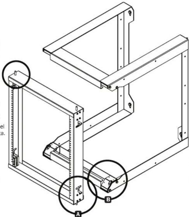
text_image
Technical diagram of a mechanical assembly with labeled components A and B, showing structural connections and mounting points.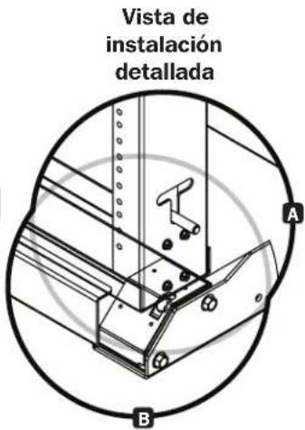
1111 W. 35th Street, Chicago, IL 60609, EE UU • tripplite.com/support
20-05-051 93-3C45 RevA
natural_image
Technical line drawing of a mechanical frame assembly (no text or symbols)English 1 • Español 7

text_image
TRIPP·LITE
1111 W. 35th Street, Chicago, IL 60609 USA • tripplite.com/support
natural_image
Technical line drawing of a mechanical bracket or frame structure (no text or symbols)Supports de montage mural (x2)
Installation/montage mural

Installation/montage mural
natural_image
Simple line drawing of a mechanical assembly inside a circle (no text or symbols)natural_image
Simple line drawing of a mechanical component inside a circular frame (no text or symbols)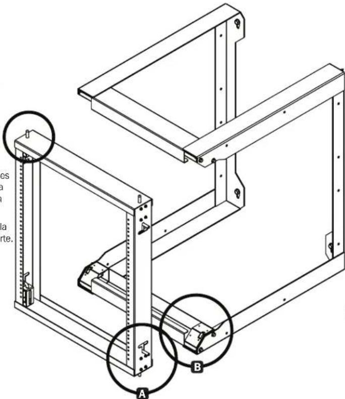
text_image
Technical diagram of a structural frame assembly with labeled components A and B, showing structural details and mounting points.natural_image
Technical diagram of a mechanical assembly with labeled parts A and B, showing alignment lines and components (no text or symbols beyond labels)1111 W. 35th Street, Chicago, IL 60609 USA • tripplite.com/support