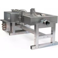
Swing Dancer Jet - Water pump ASTRALPOOL - Free user manual and instructions
Find the device manual for free Swing Dancer Jet ASTRALPOOL in PDF.


| Product type | Fountain water pump |
| Brand | AstralPool |
| Model | Swing Dancer Jet |
| Input voltage | 230 V AC |
| Power (without lighting) | 330 W |
| Jet diameter | 16/20 mm |
| Water inlet connection | 2" G |
| Protection rating | IP68 |
| Minimum safety distance | 3 m |
| Operating temperature | 4 °C to 35 °C |
| Recommended pH | 6.9 - 7.8 |
| Residual free chlorine | 0.5 - 2.0 ppm |
| Total alkalinity (TAC) | 80 - 120 ppm |
| Calcium hardness (CH) | 200 - 1000 ppm |
| Maximum salinity | 2 g/l |
| Maximum total dissolved solids (TDS) | 2000 ppm |
| Main functions | Adjustable water jet, optional LED lighting, control via control panel |
| Recommended maintenance | Perform a movement in maintenance mode once a month; check the condition of the mechanical seal after 2 years then quarterly |
| Material | Stainless steel (components) |
| Weight | Not specified, heavy device (requires multiple technicians for transport) |
Frequently Asked Questions - Swing Dancer Jet ASTRALPOOL
User questions about Swing Dancer Jet ASTRALPOOL
0 question about this device. Answer the ones you know or ask your own.
Ask a new question about this device
Download the instructions for your Water pump in PDF format for free! Find your manual Swing Dancer Jet - ASTRALPOOL and take your electronic device back in hand. On this page are published all the documents necessary for the use of your device. Swing Dancer Jet by ASTRALPOOL.
USER MANUAL Swing Dancer Jet ASTRALPOOL
natural_image
Industrial machine with metallic components and orange wiring, no visible text or symbolsEQUIPOS PARA FUENTES BRUNNENGERÄTE FOUNTAIN UNITS ÉQUIPEMENTS POUR FONTAINES APPARECCHIATURE PER UNITÀ DI ALIMENTAZIONE EQUIPAMENTOS PARA FONTES
Made in SPAIN
CE

Swing dancer jet
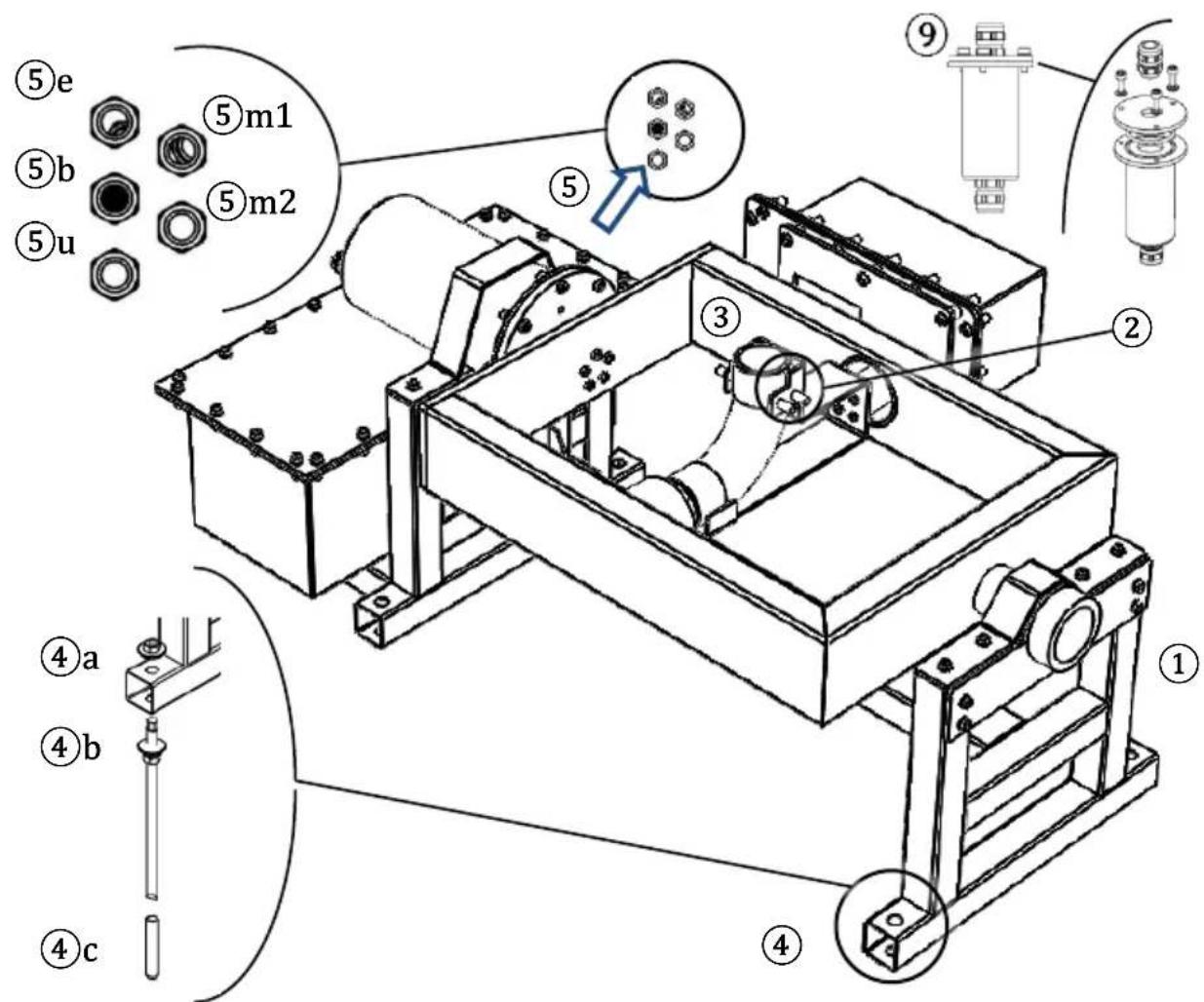
Fig. 1

Fig. 2
Fig. 3
natural_image
Technical line drawing of a mechanical device with gears and a central hub (no text or symbols)

Sicherheitsabstand
7 GARANTIE
INSTALLATION, OPERATION AND MAINTENANCE MANUAL
Swing dancer jet
TABLE OF CONTENTS
1 GENERAL SAFETY ....17
1.1 ELECTRICAL SAFETY....17
1.2 SAFETY IN USE AND CONTACT WITH WATER....17
1.3 SAFETY IN OPERATION AND MAINTENANCE....17
2 INSTALLATION AND ASSEMBLY....18
2.1 FASTENING AND LEVELLING THE UNIT 18
2.2 WIRING 19
1.1 ELECTRICAL SAFETY
- Disconnect the unit from the power supply before doing any assembly or maintenance jobs.
- Do not touch the water or get into the water while the unit is connected to the power supply.
- Connect the unit to an earth connection. Make use of one of the unit's fastening points (see chapter 2.1).
-
Connect the unit to a power supply with an earth connection, protected by the following components:
-
An RCD safety switch with a maximum residual current of 30 mA.
- A circuit breaker fuse for a 10 A current.
- Use an H07RN-F type waterproof cable.
1.2 SAFETY IN USE AND CONTACT WITH WATER
- The water in the fountain where the unit is to be fitted must meet the following conditions:
| Characteristics of the water | Minimum value | Maximum value |
| Temperature | 4 °C | 35 °C |
| pH | 6.9 | 7.8 |
| Free residual chlorine | 0.5 ppm | 2.0 ppm |
| Total alkalinity (TAC) | 80 ppm | 120 ppm |
| Calcium hardness (CH) | 200 ppm | 1,000 ppm |
| Salt level | - | 2 g/l |
| Total dissolved solids (TDS) | - | 2,000 ppm |
- If the temperature is below 4 ^ , empty the unit to prevent it from breaking due to the formation of ice inside it.
- Do not tamper with the factory-fitted waterproof seals. Otherwise, the unit could lose its warranty.
- Risk of serious injury due to entrapment or the discharge of high-pressure water.
- Set a minimum distance of 3 m between the unit and the fountain's perimeter.
- Put up signs around the fountain in line with the country's or local regulations. Examples of warnings: “Bathing is prohibited”, “Water unsafe to drink”, “Danger of electric shock”.
- Do not open or handle any of the unit's components other than those for which explanations are given in this manual.
- The unit may only be handled by authorised personnel or qualified service engineers. Do not allow unauthorised personnel or unqualified service engineers to handle it.
2 INSTALLATION AND ASSEMBLY
DANGER: Risk of serious injury. The unit is very heavy. Carry the unit with the help of mechanical hoists or between several service engineers.
IMPORTANT:
- Read the whole of the manual carefully before installing the unit.
- Check that it is in a good state of repair on removing the packaging.
- Identify all components prior to their installation.
2.1 FASTENING AND LEVELLING THE UNIT
Components required for fastening the unit (④a-④c) in C20/25 concrete:
| Component | Number |
| Anchor bolt: M12 AISI 316 threaded rod and capsule | 4 |
| DIN 9021 D.12 A4 flat washer | 4 |
| DIN 934 M12 A4 nut | 12 m |
11) [Optional] Lighting assembly
- Halospot LEDs:
- Secure all threads using a liquid threadlocker (e.g., Loctite 570).
xv) Affix the LED's base to the fixed pins on the side of the water outlet ⑥.
xvi) Mount the Halospot LEDs on their bases ⑦.
- Round LEDs
xvii) Apply liquid Teflon (e.g., Loctite 577) to the inner thread of the round LED ⑨, the inner thread of the unit's water outlet ③ and the outer thread of the nozzle ⑧.
xviii) Screw the nozzle ⑧ on the round LED ⑨ from the top and stop when the thread is level with the bottom of the LED.
xix) While holding the round LED, screw in the nozzle at the unit's water outlet ③ to the end of the thread.
xx) Clean off any excess Teflon.
xxi) Leave the Teflon to dry (for the time required according to the instructions of the product used).
xxii) Skip step 2) and go on to step 3).
12) Mount the nozzle on the water outlet ③.
13) Fasten the anchor bolts (④c) to the ground.
WARNING: Level the unit so that the water outlet works properly:
- With lighting. Level the unit so that the water line is 5 cm below the LED's lens.
- Without lighting. Level the unit so that the nozzle's water outlet is 12 cm above the water line.
14) Fasten and level the unit at each of its fastening points ④ using
• A set of nuts and washers (④a) on the top.
- Another set of nuts and washers (from top to bottom) on the bottom (④b).
2.2 WIRING
WARNING: Risk of damage to the unit. Clean all piping prior to connecting and starting the unit up.
WARNING: Risk of damage to the unit. Check that all IP68 connectors are properly sealed and that they prevent water getting through. Electrical components may become damaged by flooding and the unit could lose its warranty.
WARNING: For greater reliability when the unit is working, it is recommended that the power cable and control cable be wired separately.
WARNING: The control panel is connected to the unit through an EtherCAT communication protocol.
15) Connect the unit's water inlet (①).
16) Connect the Ethernet to the control panel (⑤e).
IMPORTANT: Follow the tightening torque instructions to close the waterproof box with an RJ45 connector (⑨).
17) Connect the unit's main power supply to mains (230 V AC) using the black cable's IP68 connector (⑤u):
• L(1): live (brown core wire)
• N(2): neutral (blue core wire)
• E(3): earth (green and yellow core wire)
INFORMATION: the ⑤m1 y ⑤m2 connections (orange wiring) are for the two servomotors' power supply. These connections must not be handled.
WARNING: Protect the water outlet from the wind and do not operate in strong wind. If the unit is installed in an area frequently exposed to strong wind, it is possible that the wind will displace the water outlet.
3.1 ON MODE AND GENERAL SETTINGS
- The unit is switched on and controlled (movement, lighting, jet height) from the fountain's general control panel, which is not included with this unit (see chapter 2.2).
3.2 LIGHTING
The lighting does not form part of this unit. See the documentation of the lighting installed.
3.3 MAINTENANCE
For the maintenance of the components made of stainless steel, see the manual attached.
It is recommended that the unit be run in maintenance mode once a month to check the shaft is working properly.
Check the state of repair of the mechanical seal two years after installation. Once this time has elapsed, complete this check every three months.
4 TECHNICAL SPECIFICATIONS
| Input voltage | 230 V AC |
| Jet nozzle diameter | 16/20 mm |
| Power load (without lighting) | 330 W |
| Water inlet connection | 2” G |
| IP protection rating (IEC 60529) | IP68 |
5 FAQs
Question
Why isn't the water coming out of the jet nozzle properly? (speed, height)
Why isn't the unit moving?
Answer
Check the pump is working properly.
Check the inside of the nozzle. It should free of all deposits and blockages.
Check the control panel is properly assembled.
Check that the unit has not been disabled by a programmed timer.
In other cases or if the answers have not resolved the problem detected, contact a service engineer (see the list of approved engineers on the product's warranty).
6 PRODUCT LABELLING
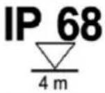 |  | 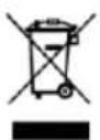 |  |  |
| IP68 protection rating | Not operational T < 4 °C | Safe management of waste electrical and electronic equipment Directive 2002/96/EC (WEEE) | The unit's documentation must be read before use | Danger of electric shocks |
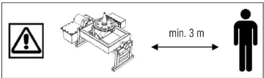
Safety distance
7 WARRANTY
The unit's warranty is subject to the term and conditions on the "Warranty certificate for fountain unit"
MANUEL D'INSTALLATION, EXPLOITATION ET D'ENTRETIEN
Swing dancer jet
SOMMAIRE
1 SÉCURITÉ GÉNÉRALE....23
1.1 SÉCURITÉ ÉLECTRIQUE .....23
1.2 SÉCURITÉ EN FONCTIONNEMENT ET CONTACT AVEC L'EAU .....23
1.3 SÉCURITÉ PENDANT L'EXPLOITATION ET L'ENTRETIEN....23
2 INSTALLATION ET MONTAGE....24
2.1 FIXATION ET NIVELLEMENT DE L'APPAREIL 24
2.2 BRANCHEMENT 25
3 EXPLOITATION ET ENTRETIEN....26
3.1 ALLUMAGE ET RÉGLAGES GÉNÉRAUX....26
3.2 ÉCLAIRAGE 26
3.3 ENTRETIEN....26
4 CARACTÉRISTIQUES TECHNIQUES......iERROR! MARCADOR NO DEFINIDO.
5 QUESTIONS ET RÉPONSES 27
6 ÉTIQUETAGE SUR PRODUIT....27
7 GARANTIE....27
1 SÉCURITÉ GÉNÉRALE
1.1 SÉCURITÉ ÉLECTRIQUE
5 PERGUNTAS E RESPOSTAS
Pergunta
Cod. 67645 / Rev. 00
Made in the EU
VAT: ES
A08246274
[en] We reserve the right to change all or part of the features of the articles or contents of this document, without prior notice.


- GARANTIE
- INSTALLATION, OPERATION AND MAINTENANCE MANUAL
- Swing dancer jet
- TABLE OF CONTENTS
- ELECTRICAL SAFETY
- SAFETY IN USE AND CONTACT WITH WATER
- INSTALLATION AND ASSEMBLY
- IMPORTANT:
- FASTENING AND LEVELLING THE UNIT
- 11) [Optional] Lighting assembly
- - Halospot LEDs:
- - Round LEDs
- WIRING
- ON MODE AND GENERAL SETTINGS
- LIGHTING
- MAINTENANCE
- TECHNICAL SPECIFICATIONS
- FAQs
- Question
- Answer
- PRODUCT LABELLING
- WARRANTY
- MANUEL D'INSTALLATION, EXPLOITATION ET D'ENTRETIEN
- SOMMAIRE
- SÉCURITÉ GÉNÉRALE
- SÉCURITÉ ÉLECTRIQUE
- PERGUNTAS E RESPOSTAS
- Pergunta
Brand : ASTRALPOOL
Model : Swing Dancer Jet
Category : Water pump