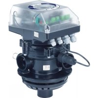
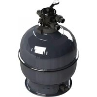
System VRAC FLAT - Water filter ASTRALPOOL - Free user manual and instructions
Find the device manual for free System VRAC FLAT ASTRALPOOL in PDF.


| Brand | AstralPool |
| Model | System VRAC FLAT |
| Product Type | Pool Water Filter |
| Power Supply | 230-115 Vac, 50-60 Hz |
| Maximum Power | 14 W |
| Maximum Working Pressure | 3.5 bar |
| Nominal Flow Rate | 12 m³/h |
| Protection | IP65 |
| Pressure Switch | 0.3 - 3.5 bar |
| Functions | Filtration, backwash, rinse, drain |
| Valve Type | Automatic multi-port valve |
| Max Water Temperature | 35 °C |
| Maintenance | Check seals, clean filter, electrical check |
| Safety | Residual current circuit breaker, grounding, IP65 protection |
| Spare Parts | Seal, actuator, electronic board, gear motor |
| Installation | Electrical connection to a control box with contactor and timer |
Frequently Asked Questions - System VRAC FLAT ASTRALPOOL
User questions about System VRAC FLAT ASTRALPOOL
0 question about this device. Answer the ones you know or ask your own.
Ask a new question about this device
Download the instructions for your Water filter in PDF format for free! Find your manual System VRAC FLAT - ASTRALPOOL and take your electronic device back in hand. On this page are published all the documents necessary for the use of your device. System VRAC FLAT by ASTRALPOOL.
USER MANUAL System VRAC FLAT ASTRALPOOL
is according to requirements stablished by the EUROPEAN UNION in the ELECTRICAL MAGNETIC COMPATIBILITY (EMC)
DIRECTIVE 89/336/CE according to following standards:
UNE-EN 61000-6-1
Electromagnetic compatibility (EMC). Generic standards. Immunity for residential, commercial and light-industrial environments.
UNE-EN 61000-6-3
Electromagnetic compatibility (EMC). Generic standards. Emission standard for residential, commercial and light-industrial environments.
And they can be sold throughout EUROPEAN UNION providing all legal requirements.
Mr. Ramon Salichs, Director /Manager
La Garriga, Abril 2010
INDEX
1 Warnings ....3
2 Characteristics
2.1 Integral parts of the Flat automatic multiport valve system (VSAF) .....4
2.2 Dimensions 4
2.3 Specifications....5
2.4 Components ....5
3 Functions
3.1 Filtration 6
3.2 Backwash....6
3.3 Rinse....6
3.4 Waste 6
4 Installation and connection of the electrical supply
4.1 Pump control....7
4.2 Power supply ....7
4.3 Electro-valve 8
5 Verification of correct working
5.1 Work position (Filtration) 8
5.2 Backwash....8
5.3 Waste 8
6 Pressure switch adjustment....8
7 Waste safety....9
8 Temporary conversion to manual working 9
9 How to switch from manual valve to automatic ....9
10 Identifying errors 9
11 Solution of possible problems .... 10
1. WARNINGS
"Important: This instructions manual, which you are now reading, contains fundamental information about the safety measures to be adopted when installing and setting up the service. This is why it is vital that both the installer and the user read these instructions before going ahead with the assembly and operation". In order to achieve maximum performance from the automatic valve it is recommendable to follow the instructions set out on the following pages.
General safety advice:
This symbol indicates the existence of danger if the corresponding warning or advice is not heeded.
DANGER. Risk of electrocution: not following this warning means there is the risk of electrocution.
DANGER. Not heeding this warning means that there is the risk of people being hurt, or equipment damaged.
ATTENTION. Not heeding this warning means that there is the risk of damage to the automatic valve or to the installation.
GENERAL SAFETY RULES GENERAL MATTERS.
The valve dealt with in this manual is specifically designed to ensure the circulation of the water through the swimming pool in its different work phases.
It has been designed to work with clean water, not above temperatures of 35 °C .
The installation must be carried out in accordance with the specific indications of each case.
The regulations in force for the prevention of accidents must be respected. Any modification which is going to be made to the electronic module must first be authorized by the manufacturer. Original spare parts and accessories authorized by the manufacturer guarantee greater security. The manufacturer of the automatic valve is free from all liability for the damage caused by any non-authorized spare parts or accessories.
While the machine is functioning the electronic and electrical parts of the valve are at low tension / voltage.
Work can only be carried out on the automatic valve or on equipment related to it once all start up equipment has been disconnected.
The user must make sure that all assembly and maintenance work is carried out by qualified and authorized personnel, and that these people have previously and properly read the installation and service instructions.
Safety in the working of the automatic valve is only guaranteed complying with, and respecting, all that is set out in the installation and service instructions.
In no case whatsoever should the tension limits be exceeded.
If the installation mal-functions or breaks down, consult the nearest representative of the manufacturer, or the technical assistance service provided by the manufacturer.
WARNINGS FOR THE SET UP AND ASSEMBLY WORK.
When connecting the electronic cables to the valve module, be careful to respect the polarity, and check that there are no cable parts inside once it is closed.
Make the connections following the instructions set out in this manual.
Make sure that the electrical cable connections to the electronic plaque are properly attached.
Check that the module box joint is correctly positioned in order to avoid water getting in. In addition, check that the cable glands are correctly placed and secured.
Special attention must be paid to ensure that water never gets into the electronic module. If the installation is put to any use other than the mentioned (and designed) use, supplementary regulations and measures to adapt the installation may be necessary.
WARNINGS FOR PUTTING THE VALVE INTO OPERATION.
Before putting the automatic valve into operation it is necessary to verify the calibration of the protective devices for the electricity supply, to ensure they are correctly positioned and attached.
NOTE: It is recommended not to use the pool while the filter equipment is functioning
WARNINGS FOR THE ASSEMBLY AND MAINTENANCE WORK.
For the set up and installation of the automatic valve the installation regulations of the country in question must be respected.
Special attention must be paid so that in no circumstances does water get into the electronic circuit of the automatic valve.
Never come into contact, not even by accident, with the moving parts of the automatic valve while it is working, and / or after it has totally stopped.
Before going ahead with any electrical or electronic maintenance work, make sure that all start up devices are blocked.
It is recommendable to follow the following steps before carrying out any operation on the automatic valve:
-
Disconnect the electricity supply to the valve.
-
Block all start up devices.
- Check that there is no tension / voltage in the circuits, not even in the auxiliary and supplementary services circuits.
The list set out should be considered as indicative, and does not rule out other security measures, it being possible that there exist specific safety regulations under other legislations.
IMPORTANT - Due to the complexity of the cases dealt with, the instructions for the installation, use and maintenance of the valve contained in this manual do not set out to examine all the possible and imaginable service and maintenance cases. If supplementary instructions were necessary, or if specific problems occurred, do not hesitate to contact with the distributor, or directly with the manufacturer of the valve.
Our automatic valves can only be installed in swimming pools or ponds that comply with the regulation HD 384.7.702. If there is any doubt about this compliance we ask you to consult your specialist.
Check the contents of the packaging.
2. CHARACTERISTICS
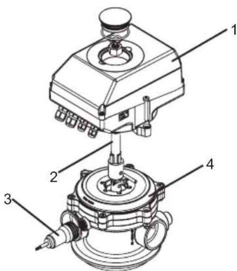
2.1 Parts making up the automatic multiport valve system
The VSAF is made up of four integral parts:
- The FLAT activator 1
- The central axis
- The pressure switch unit
- The multiport valve
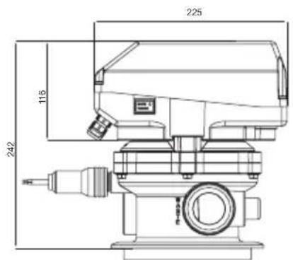
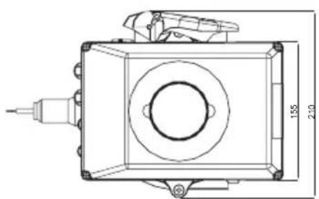
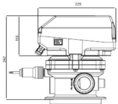
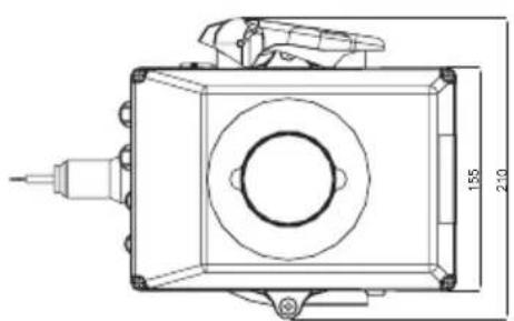
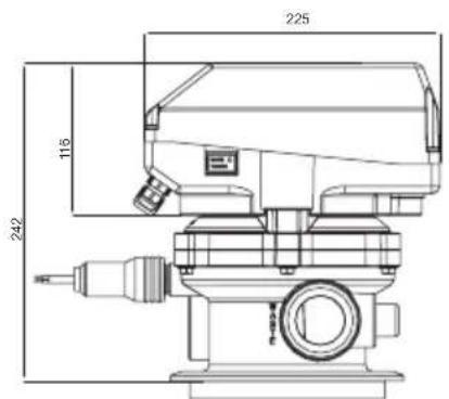
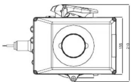
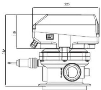
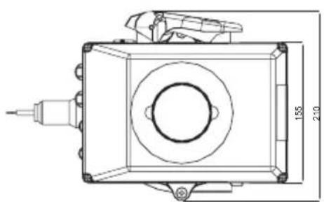
2.2 Dimensions
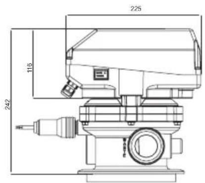
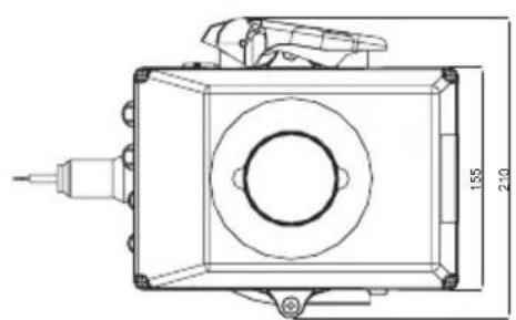
natural_image
Technical line drawing of a mechanical component with dimension annotations (155 and 240 units), no readable text or symbols beyond measurement lines.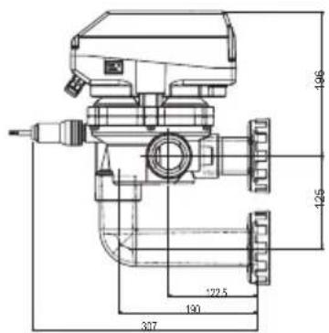
TOP SIDE
2.3 Specifications
• Power supply: 230-115 Vac / 50-60 Hz.
• Maximum power: 14 W.
• Protection for the automatic system: IP65.
• Maximum work pressure: 3,5 bar.
- Pressure switch range: 0,3 – 3,5 bar.
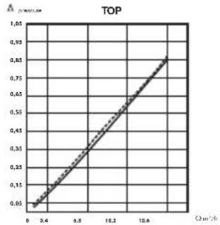
• Nominal flow = 12 m³/h
• Maximum charge loss = 0,66 bar.
Pressure loss
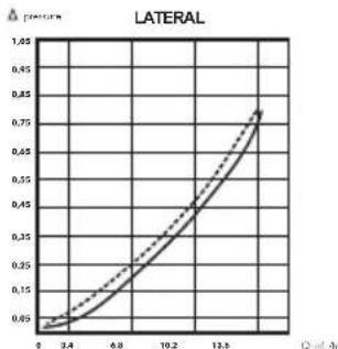
line
| x | y | | ---- | ------ | | 0 | 0.65 | | 3.4 | 0.75 | | 6.8 | 0.85 | | 10.2 | 0.95 | | 13.6 | 1.05 |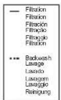
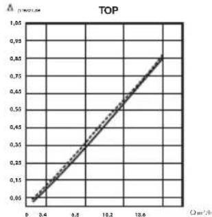
line
| x | y | | ---- | ---- | | 0.0 | 0.05 | | 0.4 | 0.15 | | 0.8 | 0.25 | | 1.2 | 0.35 | | 1.6 | 0.45 | | 2.0 | 0.55 | | 2.4 | 0.65 | | 2.8 | 0.75 | | 3.2 | 0.85 | | 3.6 | 0.95 |2.4 Automatic system components
| N Name Material Q | |||
| 1 Base ABS 1 | |||
| 2 Main core PA 66 1 | |||
| 3 Central shaft POM 1 | |||
| 4 Male shift POM 1 | |||
| 5 Cover PC | 1 | ||
| 6 Reducing bracket ABS 1 | |||
| 7 Access plug PC | 1 | ||
| 8 Indicator plug ABS 1 | |||
| 9 Cogwheel POM 1 | |||
| 10 | Pinion | POM 1 | |
| 11 | Micro bracket | PPO+FV | 1 |
| 12 | Ratchet shaft | POM 1 | |
| 13 | Ratchet | POM 1 | |
| 14 | Micro ratchet | PPO+FV | 1 |
| 15 | Electronic sheet | - | 1 |
| 16 | Waste button | - | 1 |
| 17 | Gear box - 1 | ||
| 18 | Pin | INOX | 1 |
| 19 | Gland M12 | PA | 2 |
| 20 | Gland M16 | PA | 2 |
| 21 | Gland M12 | PA | 2 |
| 22 | Gland M16 | PA | 2 |
| 23 | Bolt | INOX | 2 |
| 24 | O-ring seal | EPDM | 1 |
| 25 | Micro rise - 2 | ||
| 26 | Bolt | INOX | 3 |
| 27 | Bolt | INOX | 2 |
| 28 | Bolt | INOX | 4 |
| 29 | Bolt | INOX | 4 |
| 30 | Bolt | INOX | 1 |
| 31 | Nut | INOX | 2 |
| 32 | Nut | INOX | 3 |
| 33 | Nut | INOX | 2 |
| 34 | Nut | INOX | 1 |
| 35 | Washer | INOX | 1 |
| 36 | Washer | INOX | 1 |

3. FUNCTIONS
The VSAF carries out four functions: filtration, washing and rinsing the filter and emptying the swimming pool.
3.1 Filtration
This is the work position of the valve. Its starting and finishing are set by the timer in the operating cabinet. When the filtration of the swimming pool has finished, the valve remains in this position. The red L.E.D. must be lit up, and the green light off.
3.2 Washing the filter
The VSAF will start washing the filter when the pressure switch detects that the filter pressure is greater than the pressure graduated by the client. The green L.E.D. will be activated in these circumstances.
In the case that during the filter pressure washing the set time runs out for the filtration cycle, the VSAF will go to "filtration" and when the program time setter activates the program again, the VSAF will continue with the filter washing. This will only stay in the programming memory while the power supply is not interrupted.
The washing time can be modified from between 1 to 6 minutes, using the power-meter located on the electronic plaque.
The washing of the filter is always followed by a rinsing.

3.3 Rinsing
Rinsing will start automatically just when the washing is finished. The time is fixed and invariable: thirty (30) seconds.
3.4 Emptying
The emptying can only be activated when the valve is in the filtration position.
To carry out the emptying it is necessary to press on the emptying button (located on the right side of the VSAF) for five seconds. After these five seconds the L.E.D. light will come on, the pump will stop, the VSAF will switch to emptying, and the pump will be connected.
When the emptying is finished the client must once again press the emptying button. If the user does not stop the emptying, the latter will only be detained if the VSAF power supply is interrupted.
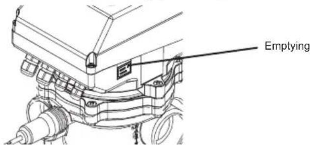

4. INSTALLATION AND CONNECTION OF THE ELECTRICAL CABINET.
Before beginning to connect the machine to the electricity supply the hydraulic part must be installed. It is recommendable for the operating cabinet to have at least the following components: thermal magnet, differential, pump contact (it is vital that the coil is 220 VAC), triple position switch and a programming timer. For the VSAF to work correctly two connections must be made to the electricity supply: for the pump control and for the power source.
4.1 Pump control
The VSAF must be connected just before the pump contact coil in order to ensure that no other apparatus connects with the pump while it is changing position. Of the two contact terminals, the MOTOR PUMP series terminal has to be connected to the terminal receiving the signal from the programming timer, triple position switch, (diagram 1).
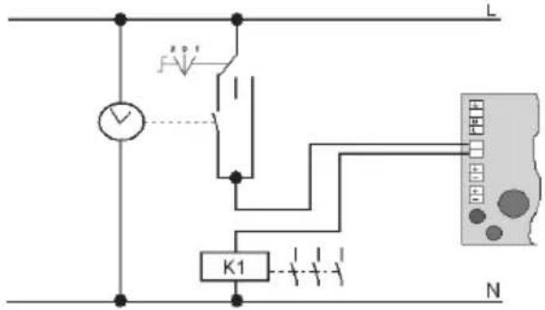
K1=220Vac
diagram 1
The multiport valve must never be connected to the terminal with neutral connected (diagram 2).
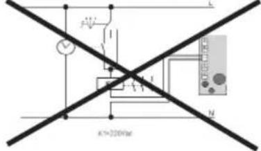
diagram 2
4.2 Power supply
The power supply to the VSAF must be 230-115 Vac and 50 – 60 Hz. The VSAF does not work with lower voltages, and higher voltages can damage the PCB components. The power supply shall be connected at the same point as the triple position switch (Diagram 3).
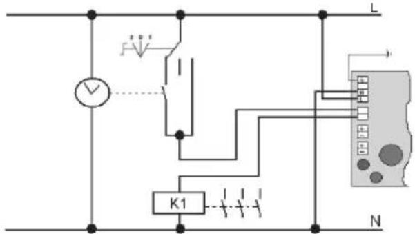
K1=220Vac
diagram 3
With electrical Systems with a tri-phasic power supply, the electrical scheme is as shown in diagram 4. If this is not correctly done the VSAF could be severely damaged.
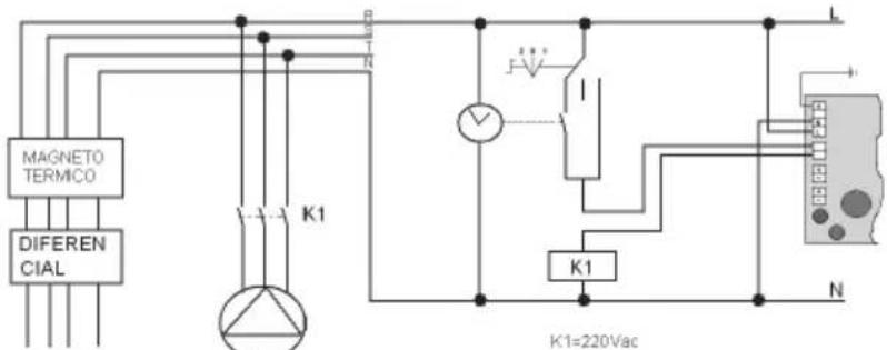
diagram 4
4.3 Electro-valve
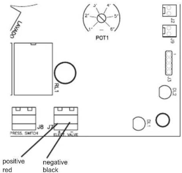
To connect the electro-valve it is necessary to take into account the polarity of the connection cables, as shown in the attached diagram.
5. VERIFICATION OF CORRECT FUNCTIONING
To carry out all the operations to check the initial functioning of the valve it is necessary to place the triple position switch of the electrical system in position 1 (forcing the pump) and check the following points:
5.1 Work position (Filtration)
This is the position in which the VSAF will be 99% of the time and to which it will reposition after a fall in the tension.
In the moment that the power supply is connected, the VSAF will switch to the filtration position, if it is not already there, and the L.E.D. test light will come on, not flashing (it is located on the plaque) and the pump will be connected. If the light does flash consult section 10 of this manual, "identification of errors.
5.2 Washing the filter
In order to force the washing of the filter it is enough just to make a connection across the pressure switch terminal, or partially shut off the swimming pool return valve. After 7 seconds the pump will stop and the green light will come on, the VSAF will go to the washing position, and the pump will reconnect. Once the time set on the washing regulation power-meter (located on the electronic plaque) has gone by, the pump will stop, the VSAF will go to rinse and the pump will re-connect. After 30 seconds the pump will stop, the valve will change from rinse position to filtration position, and then the pump will re-connect.
5.3 Emptying
When the valve is in the filtration position the emptying button can be activated, following the description and instructions given in the valve functions section of this manual. Check that the valve has made the change of position and the pump is started. Push the button again in order to finish the operation.
6. REGUALTION OF THE PRESSURE SWITCH
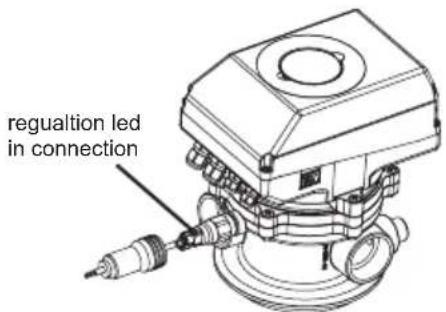
In order to correctly adjust the pressure switch it is vital that a ball valve is installed in the swimming pool filter return tube and that the VSAF is in the filtration position.
The following steps must be taken:
- Take off the pressure switch cap.
- Turn the screw until it is at the level of the plastic.
- Adjust the pressure with which you wish to start the washing by closing the ball valve located in the swimming pool return
- Loosen the pressure switch screw until the green light comes on.
- Replace the cap.
- Re-open the ball valve in the return connection.
7. SAFETY WHEN EMPTYING
The valve comes prepared so that an electro-valve can be installed into the waste circuit.
It is recommendable to use this type of valve so as to avoid water leaking out in the case that the electrical current fails and the valve remained in a position in which it could empty the swimming pool.
The electro-valve used should have a pump opening pressure as low as possible (0,4 to 0,5 bar). The tension/voltage of the solenoid must be 24 VAC.
Maintain the polarity of the solenoid connection: red cable (+) / black cable (-).
8. SWITCHING FROM THE AUTOMATIC VALVE TO MANUAL
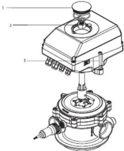
To dismount the electronic module and to switch to the manual selective valve, reduce the system pressure and proceed as set out in the following steps:
- Dismount the top screw cap, using two screw drivers to push it from both sides.
- Dismount the indicator cap by turning it, the principal axis attachment screw and the washer
- Unscrew the two side screws that fix the automatic system to the valve body.
- Carefully pull the automatic system with both hands until it comes out completely of the main axis.
- Take out the slide-bolt hitting it softly and take out the axis vertically.
- Finally, set up the little lever fixed to the side of the body, and fix it with the same slide-bolt.

9. HOW TO SWITCH FROM MANUAL VALVE TO AUTOMATIC
It is also possible to convert a FLAT multiport valve from manual to automatic. To do this go through the steps set out in the process described in the previous section, but in the reverse order.
- Take off the little lever, having first taken off the attachment slide-bolt.
- Fix the principal axis using the same slide-bolt of the little lever.
- Place the activator and fix it with the screws.
- Thread the screw and assemble the indicator and the top screw cap.
- Assemble the pressure switch and fix the electrical connections following the specifications set out in the previous sections.
10. ERROR IDENTIFICATION

By checking the test L.E.D., to see if it is permanently on or flashing, we can verify everything is working correctly and that the valve is properly connected.
Flashing warnings also advise us of possible failures in the correct functioning of the system:
2 flashes: cannot find stop micro. It is possible the Micro is broken.
4 flashes: excessive consumption by motor. Possible that the brake on the distribution bell is on.
6 flashes: the distribution bell ascent micro detection has failed.
11. SOLUTIONS FOR POSSIBLE PROBLEMS
| PROBLEM CAUSE SOLUTION | ||
| The activator does not work and the red L.E.D. Light is flashing twice | Failure of the position micro Contact technical assistance | |
| EI activator does not work and the red light flashes 4 times | The valve distributor is blocked Disconnect the power supply and take off the activator. Take off the valve lid and clean the distributor bell | |
| EI activator does not work and the red light flashes 6 times | Problem with the bell ascent micro Check the connection from the micro to the J2 plaque. If the problem persists, get in contact with Technical Assistance | |
| The waste button does not work | The connection lead has become disconnected | Check it is correctly connected |
| The valve keeps on doing washings with the pressure switch L.E.D. lit up | The pressure switch is not correctly graduated | Consult the manual to correctly adjust the pressure switch |
| The return ball valve is closed, or nearly closed | Open the valve | |
| There is a faulty connection in the pressure switch circuit | Check the pressure switch connection cable | |
| The pump does not stop while it is changing position | The J10 has not been correctly connected to the control cabinet | Check that the connection to the cabinet has been made as set out in the diagram |
| The waste water electro-valve does not open (in the case that one has been installed) | The polarity of the cables has not been respected | Check the cable connections: red to positive and black to negative |
| Error in the electronic plaque Use a tester to check the tension in the electro-valve terminal: if it is less than 15 VCC, contact Technical Assistance | ||
| Error in the electro-valve If the tension is correct, the problem has to be in the electro-valve | ||
TABLE DES MATIÈRES
1 Avertissements.... 12
2 Caractéristiques
2.1 Ensembles de la Vanne Multivoies Automatique Flat (VSAF) 13
2.2 Dimensions 13
2.2 Dimensions
natural_image
Technical line drawing of a mechanical component with dimension annotations (no readable text or symbols)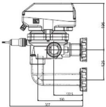
TOP LATERAL
2.3 Spécifications
3. FONCTIONS
9. COMMENT PASSER LA VANNE DE MANUELLE À AUTOMATIQUE
2.2 Dimensiones
natural_image
Technical line drawing of a mechanical component with dimension annotations (no readable text or symbols)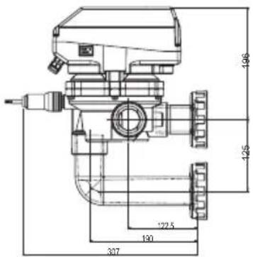
TOP LATERAL
3. FUNCIONES
K1=220Vac esquema 1
esquema 2
4.2 Alimentación
K1=220Vac esquema 3
esquema 4
4.3 Electroválvula

9. CÓMO PASAR LA VÁLVULA MANUAL A AUTOMÁTICA
2.2 Dimensões
natural_image
Technical line drawing of a mechanical component with dimension annotations (1.55 and 2.10), no readable text or symbols beyond measurement lines.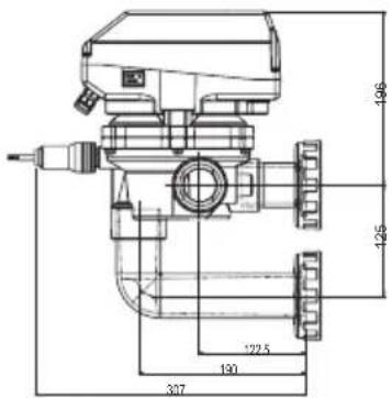
TOPO LATERAL
2.3 Especificações
line
| x | y | | ---- | ----- | | 0.0 | 0.65 | | 0.4 | 0.75 | | 0.8 | 0.95 | | 1.2 | 1.25 | | 1.6 | 1.65 | | 2.0 | 2.15 | | 2.4 | 2.75 | | 2.8 | 3.45 | | 3.2 | 4.25 | | 3.6 | 5.15 | | 4.0 | 6.15 | | 4.4 | 7.15 | | 4.8 | 8.15 | | 5.2 | 9.15 | | 5.6 | 10.15 | | 6.0 | 11.15 | | 6.4 | 12.15 | | 6.8 | 13.15 | | 7.2 | 14.15 | | 7.6 | 15.15 | | 8.0 | 16.15 | | 8.4 | 17.15 | | 8.8 | 18.15 | | 9.2 | 19.15 | | 9.6 | 20.15 | | 10.0 | 21.15 | | 10.4 | 22.15 | | 10.8 | 23.15 | | 11.2 | 24.15 | | 11.6 | 25.15 | | 12.0 | 26.15 | | 12.4 | 27.15 | | 12.8 | 28.15 | | 13.2 | 29.15 | | 13.6 | 30.15 | | 14.0 | 31.15 | | 14.4 | 32.15 | | 14.8 | 33.15 | | 15.2 | 34.15 | | 15.6 | 35.15 | | 16.0 | 36.15 | | 16.4 | 37.15 | | 16.8 | 38.15 | | 17.2 | 39.15 | | 17.6 | 40.15 | | 18.0 | 41.15 | | 18.4 | 42.15 | | 18.8 | 43.15 | | 19.2 | 44.15 | | 19.6 | 45.15 | | 20.0 | 46.15 | | 20.4 | 47.15 | | 20.8 | 48.15 | | 21.2 | 49.15 | | 21.6 | 50.15 | | 22.0 | 51.15 | | 22.4 | 52.15 | | 22.8 | 53.15 | | 23.2 | 54.15 | | 23.6 | 55.15 | | 24.0 | 56.15 | | 24.4 | 57.15 | | 24.8 | 58.15 | | 25.2 | 59.15 | | 25.6 | 60.15 | | 26.0 | 61.15 | | 26.4 | 62.15 | | 26.8 | 63.15 | | 27.2 | 64.15 | | 27.6 | 65.15 | | 28.0 | 66.15 | | 28.4 | 67.15 | | 28.8 | 68.15 | | 29.2 | 69.15 | | 29.6 | 70.15 | | 30.0 | 71.15 | | Note: The data is already in the image as it is not plotted on the graph.
line
| x | y | | ---- | ----- | | 0.0 | 0.05 | | 0.4 | 0.15 | | 0.8 | 0.25 | | 1.2 | 0.35 | | 1.6 | 0.45 | | 2.0 | 0.55 | | 2.4 | 0.65 | | 2.8 | 0.75 | | 3.2 | 0.85 | | 3.6 | 0.95 |3. FUNÇÕES
K1=220Vac esquema 1
esquema 2
4.2 Alimentação
K1=220Vac esquema 3
9. COMO PASSAR A VÁLVULA MANUAL PARA AUTOMÁTICA
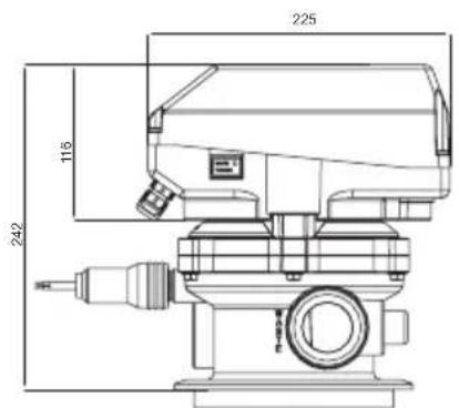
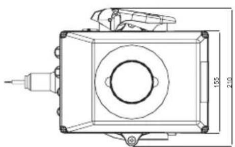
2.2 Dimensioni
natural_image
Technical line drawing of a mechanical component with dimension annotations (1.55 and 2.10), no readable text or symbols beyond measurement lines.
TOPO LATERALE
2.3 Specificazioni
3. FUNZIONI
K1=220Vac
schema 1
schema 2
4.2 Alimentazione
K1=220Vac
schema 3

9. COME CONVERTIRE LA VALVOLA MANUALE IN VALVOLA AUTOMATICA
2.2 Dimensioni
natural_image
Technical line drawing of a mechanical component with dimension annotations (no readable text or symbols)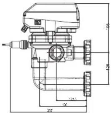
TOP SEITLICH
line
| Cm/s | Δ | | ---- | --- | | 0.0 | 0.05 | | 0.4 | 0.15 | | 0.8 | 0.25 | | 1.2 | 0.35 | | 1.6 | 0.45 | | 2.0 | 0.55 | | 2.4 | 0.65 | | 2.8 | 0.75 | | 3.2 | 0.85 | | 3.6 | 0.95 |3. FUNKTIONEN
K1=220Vac
schema 1
schema 2
K1=220Vac
schema 3
9. WIE DAS VENTIL VON MANUELL AUF AUTOMATISCH UMSTELLEN
natural_image
Completely black image with no visible content, text, or symbols.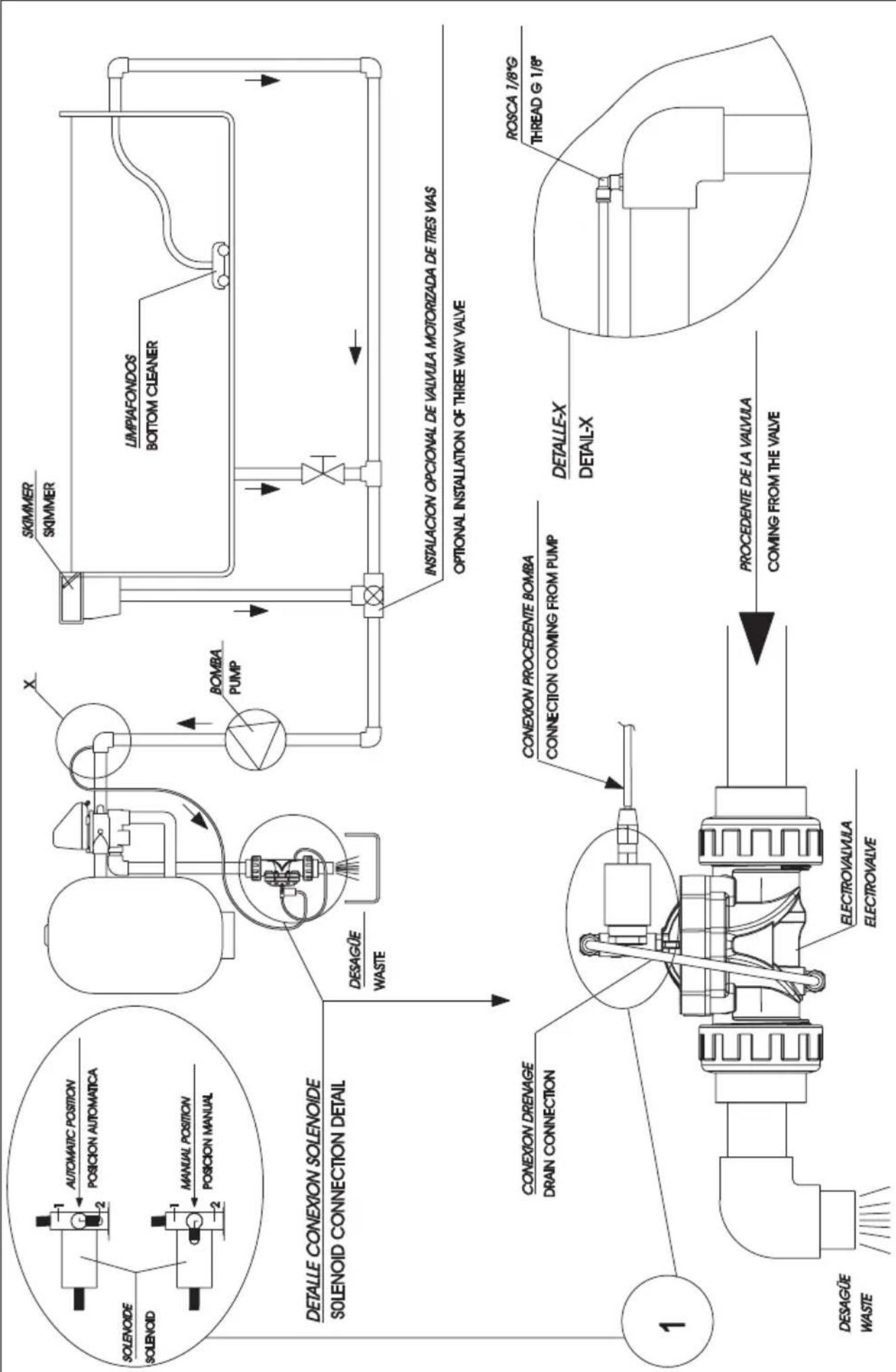
flowchart
graph TD
    A["SOLENOIDE"] --> B["Automatic Position"]
    B --> C["POSICION AUTOMATICA"]
    D["SOLENOID"] --> E["Manual Position"]
    E --> F["POSICION MANUAL"]
    G["DETALLE CONEXION SOLENOIDE"] --> H["SOLENOID CONNECTION DETAIL"]
    I["DESAGÜE WASTE"] --> J["CONEXION DRENAGE"]
    J --> K["DRAIN CONNECTION"]
    L["1"] --> M["DESAĞÜE WASTE"]
    N["EXTRAFAVULA ELECTROVALVE"] --> O["PROCEDENTE DE LA VALVULA"]
    P["EXTRAFAVULA CONNECTOR"] --> Q["COMING FROM THE VALVE"]
    R["EXTRAFAVULA SWITCH"] --> S["PROCEDENTE DE LA VALVULA"]
    T["EXTRAFAVULA SWITCH"] --> U["COMING FROM THE VALVE"]
    V["EXTRAFAVULA SWITCH"] --> W["PROCEDENTE DE LA VALVULA"]
    X["EXTRAFAVULA SWITCH"] --> Y["COMING FROM THE VALVE"]
    Z["EXTRAFAVULA SWITCH"] --> AA["PROCEDENTE DE LA VALVULA"]
    AB["LIMPIAFONDOS BOTTOM CLEANER"] --> AC["INSTALLACION OPCIONAL DE VALVULA MOTORIZADA DE TRES VIAS"]
    AD["LIMPIAFONDOS BOTTOM CLEANER"] --> AE["OPTIONAL INSTALLATION OF THREE WAY VALVE"]
    AF["LIMPIAFONDOS BOTTOM CLEANER"] --> AG["LIMPIAFONDOS BOTTOM CLEANER"]
    AH["LIMPIAFONDOS BOTTOM CLEANER"] --> AI["LIMPIAFONDOS BOTTOM CLEANER"]
ESQUEMA INSTALACION VÁLVULA HIDRAULICA, PARA MONTAJE EN VALVULA SELECTORA AUTOMATICA DIAGRAM INSTALLATION HYDRAULIC VALVE, FOR ASSEMBLY WITH AUTOMATIC MULTIPORT VALVE

natural_image
Completely black image with no visible content, text, or symbols.TECHNICAL CHARACTERISTICS
| FLAT automatic | ||
| 112" 112" | ||
| VALVE 43512 43513 | ||
| Position TOP SIDE | ||
| Working pressure 3,5 bar (25°C) | ||
| Flow 12m | ^3/h - 53 GPM | |
| ACTUATOR | ||
| Protection IP 65 | ||
| Power supply 230-115 VAC | ||
| OPTIONS | ||
| Electrical cabinet Works as a cabinet forming part of the installation | ||
| Recommended safety systems Electro-valve (for waste water): necessary for assemblies below the swimming pool level. | ||

www.astralpool.com
- INDEX
- WARNINGS
- GENERAL SAFETY RULES GENERAL MATTERS.
- WARNINGS FOR THE SET UP AND ASSEMBLY WORK.
- WARNINGS FOR PUTTING THE VALVE INTO OPERATION.
- WARNINGS FOR THE ASSEMBLY AND MAINTENANCE WORK.
- CHARACTERISTICS
- Specifications
- Automatic system components
- FUNCTIONS
- Filtration
- Washing the filter
- Rinsing
- Emptying
- INSTALLATION AND CONNECTION OF THE ELECTRICAL CABINET.
- Pump control
- Power supply
- Electro-valve
- VERIFICATION OF CORRECT FUNCTIONING
- Work position (Filtration)
- Washing the filter
- Emptying
- REGUALTION OF THE PRESSURE SWITCH
- SAFETY WHEN EMPTYING
- SWITCHING FROM THE AUTOMATIC VALVE TO MANUAL
- HOW TO SWITCH FROM MANUAL VALVE TO AUTOMATIC
- ERROR IDENTIFICATION
- SOLUTIONS FOR POSSIBLE PROBLEMS
- TABLE DES MATIÈRES
- Spécifications
- FONCTIONS
- COMMENT PASSER LA VANNE DE MANUELLE À AUTOMATIQUE
- FUNCIONES
- Alimentación
- Electroválvula
- CÓMO PASAR LA VÁLVULA MANUAL A AUTOMÁTICA
- Especificações
- FUNÇÕES
- Alimentação
- COMO PASSAR A VÁLVULA MANUAL PARA AUTOMÁTICA
- Specificazioni
- FUNZIONI
- Alimentazione
- COME CONVERTIRE LA VALVOLA MANUALE IN VALVOLA AUTOMATICA
- FUNKTIONEN
- WIE DAS VENTIL VON MANUELL AUF AUTOMATISCH UMSTELLEN
- TECHNICAL CHARACTERISTICS
Brand : ASTRALPOOL
Model : System VRAC FLAT
Category : Water filter