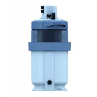
NanoFiber - Water filter ASTRALPOOL - Free user manual and instructions
Find the device manual for free NanoFiber ASTRALPOOL in PDF.


| Product type | Pool water filter |
| Brand | AstralPool |
| Model | NanoFiber |
| Filtering medium | Treated fiber cartridge, filtration down to 5 microns |
| Maximum working pressure | Not specified, but standard 2" multiport valve |
| Maximum water temperature | 35 °C |
| Minimum distance from pool edge | 3.5 meters |
| Recommended installation height | 0.50 m below water level |
| Power supply | 220-240 V, 50-60 Hz |
| Required electrical protection | 30 mA differential circuit breaker and thermal-magnetic |
| Compatible valve type | Manual multiport valve (code 07444) or automatic (code 57187) |
| Dimensions (height) | Approximately 60 cm (estimated) |
| Weight | Approximately 5 kg (estimated) |
| Box contents | NanoFiber filter, installed cartridge, pressure gauge, connections, cable glands, instruction manual |
| Main functions | Filtration, backwash, recirculation, drain, rinse, closed |
| Cartridge maintenance | Clean by backwashing when pressure increases by 0.5 kg/cm²; replacement recommended every 3 years |
| Exterior cleaning | Do not use solvents; clean with a soft cloth |
| Main safety instructions | Disconnect power before servicing; do not use without water; observe safety distances; use a ground cable |
| Available spare parts | Replacement cartridge, multiport valve, pressure gauge, seals, cable glands, IP68 cap |
| Warranty | Follow instructions and use original parts to maintain warranty |
| Compliance standards | Directives 2006/95/EC, 2006/42/EC, 97/23/EC, 2014/30/EU; standards UNE-EN |
Frequently Asked Questions - NanoFiber ASTRALPOOL
User questions about NanoFiber ASTRALPOOL
0 question about this device. Answer the ones you know or ask your own.
Ask a new question about this device
Download the instructions for your Water filter in PDF format for free! Find your manual NanoFiber - ASTRALPOOL and take your electronic device back in hand. On this page are published all the documents necessary for the use of your device. NanoFiber by ASTRALPOOL.
USER MANUAL NanoFiber ASTRALPOOL
NanoFiber Filter Auto
Filtre NanoFiber Auto
Filtro NanoFiber Auto
Filtro NanoFiber Auto
NanoFiber-Filter Auto
Filtro NanoFiber Auto
67355
\$7356
67357
67509
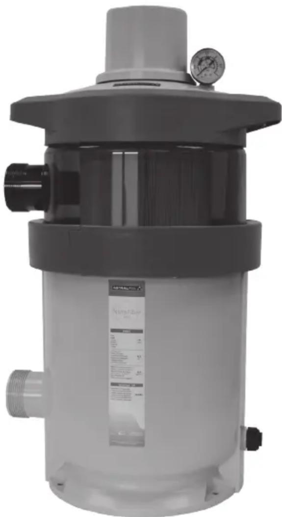
natural_image
Exterior view of a modern industrial vacuum cleaner with control panel and pressure gauge (no visible text or symbols)CE

INSTALLATION AND MAINTENANCE MANUAL
MANUEL D'INSTALLATION ET D'ENTRETIEN
MANUAL DE INSTRUÇÕES E MANUTENÇÃO
ASTRALPOOL
ENGLISH
IMPORTANT: The instruction manual you are holding includes essential information on the safety measures to be implemented for installation and start-up. Therefore, the installer as well as the user must read the instructions before beginning installation and start-up. Keep this manual for future reference.
To achieve optimum performance of the Nanofiber Filter Auto follow the instructions provided below:
General safety prescriptions:
These symbols ⚠️ ⚠️ ⚣️ indicate the possibility of danger as the consequence of not respecting the corresponding prescriptions.
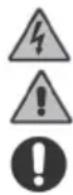
DANGER. Risk of electrocution. The lack of warning of this prescription involves a risk of electrocution.
DANGER. The lack of warning of this prescription involves a risk of personal injury or material damages.
WARNING. The lack of warning of this prescription involves a risk of damage to the filter or the installation.
GENERAL SAFETY REGULATIONS.

The filter described in this manual has been specially designed to provide correct water filtration in the swimming pool.

It has been designed to work with clean water at temperatures not exceeding 35^ C.
The installation must be carried out in accordance with the specific instructions for each particular implementation.

Current in-force regulations for the prevention of accidents must be observed. Any modification to the filter's electronic module requires the prior authorisation from the manufacturer. Original spare parts and accessories authorised by the manufacturer will guarantee greater safety. The manufacturer of this filter is exempt from all responsibility for any damage caused by non-authorised spare parts or accessories.
During operation, the filter's electric and electronic parts have electric power connected to them.
Any work to the filter and any equipment connected to it, must only be carried out when the start-up devices have been disconnected.
The user must ensure that installation and maintenance work is carried out by adequately qualified and authorised personnel, and these have previously carefully read the installation and service instructions.
Filter operational safety is only guaranteed by full compliance and respect of the installation and service instructions.
The appliance is not to be used by persons (including children) with reduced physical, sensory or mental capabilities, or lack of experience and knowledge, unless they have been given supervision or instruction. Children being supervised not to play with the appliance.

ADVICE DURING INSTALLATION AND ASSEMBLY OPERATIONS.
During the connection operations of the electrical wiring to the filter modules, great attention must be given to polarity, and it must be verified that pieces of wiring are not left inside after closing.
Make all connections by following the instructions in this manual.
It should be verified that the electrical wiring connections to the electronic card are firmly made.
The seal on the module's box should be checked for correct positioning to prevent the entry of water, it should also be checked that the compression gland is also correctly located.

Particular attention should be paid, so that, under no circumstances, is it possible for water to enter the electronic module. In the case where the intended use is not that for which the valve was designed, adaptation and supplementary technical regulations may be necessary.

ADVICE FOR WHEN PUTTING INTO SERVICE.
Before putting the filter into service, it is necessary to verify the calibration of the electrical protection devices in the operations cabinet and that they are correctly positioned and fixed in place.
The maximum voltage values must never be exceeded under any circumstances.
In the case of incorrect operation or a fault, please contact the closest manufacturer's representative or technical assistance service.
NOTE: It is recommended that the bathing facilities are not used while the fi ltration equipment is in operation.

ADVICE DURING INSTALLATION AND MAINTENANCE WORK.
National installation regulations must be taken into account when assembling and installing the filter. Extra care must be taken so that it is not possible, under any circumstances, for water to enter the filter electronic circuit.

All contact, including accidental, must be avoided at all times with the moving parts in the filter during operation and/or before complete shutdown.
Before carrying out any maintenance or any other electrical or electronic work, it must be ensured that switch-on devices are locked.

It is recommended that the following steps be taken before performing any maintenance on the filter:
1- Remove electrical power to the filter.
2- Lock the switch-on devices.
3- Verify that there is no electrical power being applied to the circuits, including auxiliary and supplementary services.
This list must be considered indicative and not binding with respect to safety, there may be other specific safety standards in particular regulations.

IMPORTANT: due to the complexity of the situations covered, the instructions for installation, use and maintenance contained in this manual, do not make any attempt to cover all possible service and maintenance cases. If additional instructions are necessary or specific problems arise, please do not hesitate in contacting the distributor or the filter manufacturer directly.
Our filters may only be installed in swimming or other pools which fully comply with the HD 384.7.702 standard. When any doubt exists a specialist should be consulted.
1. CONTENT OF 67355-67356-67357:
Inside the box, you will find:
- Nanofiber filter
- Nanofiber filter cartridge (inside the filter)
- Bag of components:
Pressure gauge
Connections
Additional cable gland
Operating Instructions
2. CONTENT OF 67509 KIT:
If you have purchased the 67509 KIT you must begin the installation in step n°7. Inside the box, you will find:
- Cover assembly
- Bag of components:
Pressure gauge
Additional cable gland
Operating Instructions
3. GENERAL CHARACTERISTICS:
The filter medium inside the cartridge is a treated nanofiber designed to separate dirt particles as small as 5 microns.
Under no circumstances may the manufacturer be held liable for the assembly, installation or start-up of the filter, nor for its subsequent handling, or the addition of hydraulic or electric components that have not already been installed in your facility.
4. INSTALLATION:
The filter should be as close as possible to the pool, but neither the filter nor the power cable should ever be installed less than 3.5 m away from the edge of the pool, and preferably 0.50 m below the level of the pool's water surface. Make sure there is drainage available at the place where the filter is to be installed.
It is recommended that the NanoFiber filter be fitted together with an AstralPool selector valve. There is a manual valve (code 07444) and a basic automatic one (code 57187).
The valve is sold separately.
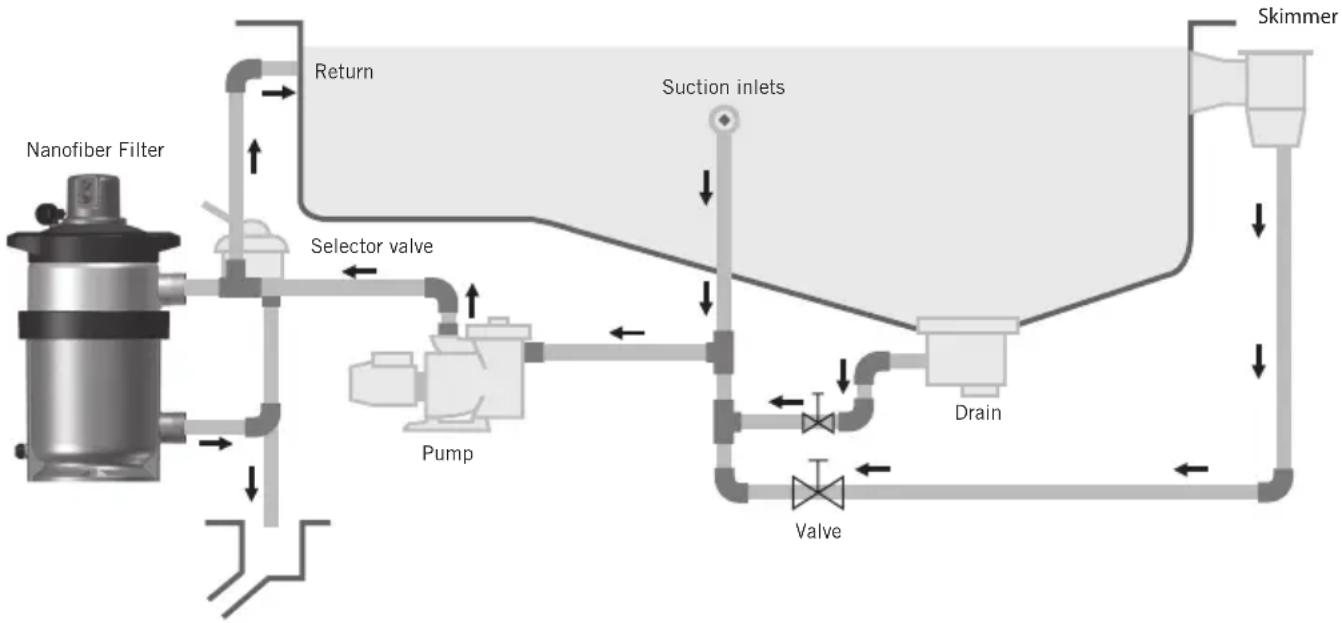
flowchart
graph TD
    A["Nanofiber Filter"] --> B["Return"]
    B --> C["Selector valve"]
    C --> D["Pump"]
    D --> E["Suction inlets"]
    E --> F["Drain"]
    F --> G["Valve"]
    G --> H["Skimmer"]
    H --> I["Return"]
    style A fill:#f9f,stroke:#333
    style B fill:#ccf,stroke:#333
    style C fill:#cfc,stroke:#333
    style D fill:#fcc,stroke:#333
    style E fill:#cff,stroke:#333
    style F fill:#ffc,stroke:#333
    style G fill:#fcc,stroke:#333
    style H fill:#cfc,stroke:#333
    style I fill:#fcc,stroke:#333
ATTENTION
If the filter is installed indoors, a correctly sized drain should be installed, to drain off as much water as possible from the swimming pool, to avoid flooding risks of the premises or adjoining areas. If this is not done, the filter manufacturer will not be held liable for possible damage to third parties caused by the filter.
Nanofibre is designed to work with clean water at temperatures that do not exceed 35 °C .
IMPORTANT: Do not use an iron and hemp pipe for the selector valve connection, it is essential to use plastic accessories and TEFLON tape. Pipe terminals are available threaded fixing in 1 12 “ and 2”.
Always leave enough space round the filter in order to perform the necessary examinations and maintenance during the filter's life.
5. ASSEMBLY:
Follow these indications for a correct assembly of the filter:
1.- Place the filter on a horizontal and clean surface.
2.- Place the filter in its final position. There are three holes at the base of the filter to secure it in place. The fastenings are not supplied.
3.- Fit the 2" multiport valve (manual code 07444 or automatic code 57187) inside the filter, whilst ensuring that the seals between the valve and the filter are in the correct position.
4.- Glue the sleeve (code 65289) that comes with the NanoFiber filter to the 2" connection at the bottom of the valve.
5.- Perform the three connections of the selector valve: pump piping to the valve, valve to the waste drain and valve to the pool return. Each of these three outlets is clearly identified on the valve.
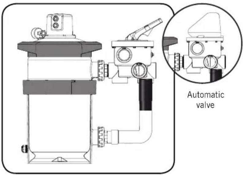
- Gluing sleeve 65289 -
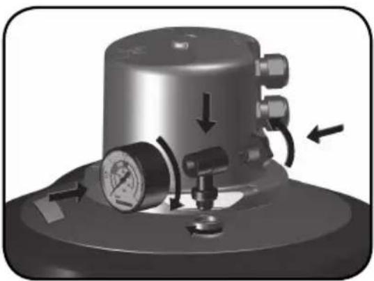
6.- Set the manometer T, the joint, the manometer and the air drainage (see exploded view). It is not necessary to use teflon tape, as the watertightness is guaranteed in this case by the joint. Do not tighten the manometer T with a tool, as manually will be sufficient.
natural_image
Mechanical pressure regulator device with gauges and adjustment knobs (no visible text or symbols)- Assembly of the manometer -
6. POSITION OF THE CARTRIDGE:
The cartridge comes properly fitted from the factory.
If you wish to remove the filter in the future, follow the steps described below:
-
Stop the filtration pump and set the valve to the Off position.
-
Open the drainage cap and release the air.
-
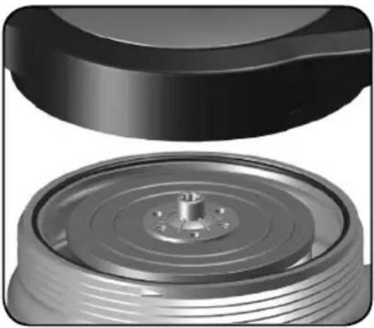
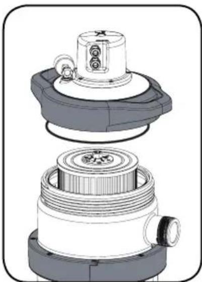
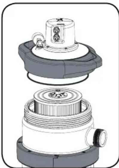
Unscrew and remove the cover assembly.
-
Remove the cartridge.
-
Put a new cartridge in place, check that it is well secured and that it can be turned with your hand.
-
Put the seal in place and check that it is firmly in position.
-
Screw the cover assembly back in.
-
Set the valve to the Filtration position.
-
Close the drainage cap until there is no longer any air inside the filter.
natural_image
Close-up of a mechanical component with a cylindrical base and flange, showing internal components (no text or symbols visible)Warning: when the filter is running check that no water leaks from the lid.
Note: the manufacturer takes no responsibility for any damage to the filter when the cartridge is being changed.
7. CONNECTION:
There are three types of connection depending on a facility's characteristics:
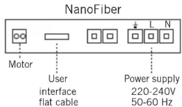
- Connection with a manual valve (code 07444). To connect the filter using a manual valve, first remove the four upper screws and the pressure gauge so that the PCB (Printed Circuit Board) can be accessed. In order to connect the filter to the power supply and use the manual valve, you must remove the cable gland from the connection not used and replace it with the IP68 cap supplied with the filter. The other cable gland will be used to run the power cable through it that must be connected to the switchboard's terminal block and suitably protected using a residual-current device (30 mA) and a thermal magnetic circuit breaker sized according to the characteristics of the installation and the regulations that apply in your country.
To enable it, place your finger on the touch panel for a maximum of 20 seconds, following which it will switch off automatically.
If you prefer, you can press the button twice and the filter will automatically turn for 40 seconds. If you wish to stop it from working before the 40 seconds are up, press the button twice once again.
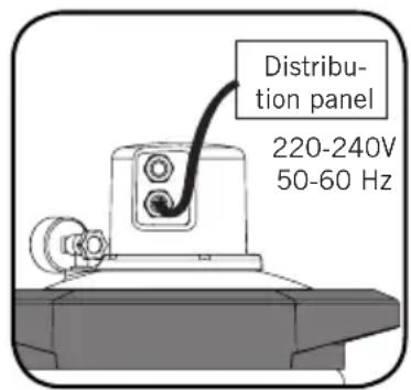
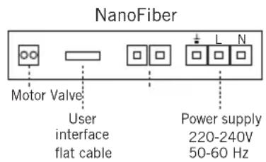
- Connection with an automatic valve (code 57187). To connect the filter using an automatic valve, first remove the upper four screws and the pressure gauge so that the PCB (Printed Circuit Board) can be accessed. Connect the cables as shown in the drawing (using a screwdriver, tighten the tab so that the cable can be threaded through or out of the hole). The connection to the valve should be parallel to the electrovalve's drainage signal (5 - 24 V AC/DC self-limited to 20 mA). The power connection should be done as described in the previous section.
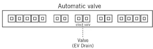
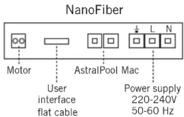
- Connection to AstralPool MAC. To connect the filter to AstralPool MAC, first turn off the power of all units and remove the four screws from the upper lid and the pressure gauge so that the PCB (Printed Circuit Board) can be accessed. Connect the cables as shown in the drawing (using a screwdriver, tighten the tab so that the cable can be threaded through or out of the hole). The connection to AstralPool MAC should be parallel to electrovalve's drainage (EV DRAIN). To carry out this by-pass, it is preferable to use the APMac Connection Kit (ask your dealer for details). The power supply should NOT run through the APMac, but through the switchboard instead using suitably protected wiring as described above in this manual.
IMPORTANTE:
- The multiple disconnection device must be used with a separation of at least 3 mm between contacts in order to disconnect the power pack.
- Use a rigid cable as a network connection. If a flexible cable is used for the network connection, terminals must be used for connecting it to the terminals of the unit's electric circuit.
- The unit should be connected to a socket (see the unit's characteristics on the label) with an earth connection, protected by a residual-current device (RCD) with a residual working current set to no more than 30 mA.
- Check that the unit's earth cable is properly placed and connected.
- Ensure that the installation and electrical connections are fit for purpose, otherwise the unit's manufacturer will decline all liability and consider the warranty to be invalid.
- There may be special regulations for the installation.
- Danger of electrocution in the event of an unsuitable network connection.
- The network cable must be connected by a qualified and authorised expert.
- For 230 V use an H07 RN-F3 type power cable and adapt the section of the unit's power cable and its length.
- If the power cable becomes damaged, it must be replaced by the manufacturer, your after-sales service engineer or a similarly qualified person in order to avoid hazards.
8. START-UP:
The first time, proceed as follows:
-
Open the air bleed cap to blow out the air.
-
Place the selector valve in the "FILTER" position, only in installations with manual valve.
-
Open the valves controlling the swimming pool suction pipes.
-
Close the air bleed cap when water starts to come out.
-
Run the pump and the filter will be ready to start the filtering cycles for the water in the swimming pool.
IMPORTANT: The pump should be switched off when the position of the selector valve handle is being changed.
9. FILTRATION:
OPERATIONS TO BE PERFORMED ONLY IN INSTALLATIONS WITH MANUAL VALVE.
With the pump switched off, place the handle of the selector valve in the "FILTERING" position.
Switch on the pump.
When starting up for the first time, read the pressure of the pressure gauge. It is recommended to take note of this pressure, as later it will be used to know whether the filter is dirty and if “WASHING” is required. “WASHING” should be done when the pressure gauge indicates an increase of 0.5 kg/cm^2 with respect to the initial pressure of the filter. It is advisable to observe the pressure gauge from time to time as this indicates the degree of saturation of the filter.
Bear in mind that the valves at the bottom of the pool and the skimmers will be adjusted according to the amount of floating particles on the surface of the water. The main drain and skimmer valves will be regulated according to the quantity of floating material found on the surface of the water. Bear in mind that with the main drain valve fully open there will be little suction from the skimmers. If the surface sweep of the skimmers is to be stronger, reduce the flow from the main drain.

Example:
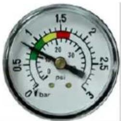
0,8 kg/cm ^3 : Initial pressure of the filter at the start of a filtering cycle.
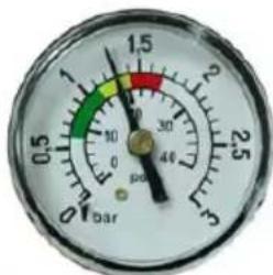
1,3 kg/cm ^2 : The pressure is 0.5 kg/cm ^2 more than the initial pressure, indicating that WASHING is required.
Note: the initial operating point will depend on the design of the installation and the flow rate used.
BACKWASH:
When the pressure has reached 0.5 kg/cm^2 above the initial pressure setting, this means that the cartridge cannot take in any more dirt and must be backwashed in the following way:
The multiport valve should be set to the Backwash position. Open the sump and non-return valves, and switch the pump on. To enable it, place your finger on the touch panel for a maximum of 20 seconds, following which it will switch off automatically. If you prefer, you can press the button twice and the filter will automatically turn for 40 seconds. If you wish to stop it from working before the 40 seconds are up, press the button twice once again.
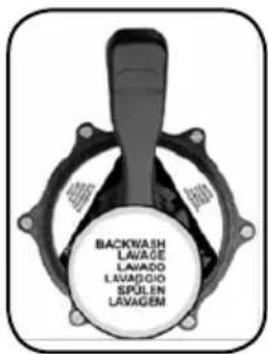
Following this operation, all of the dirt obstructing the cartridge will have been poured into the drainage pipe.
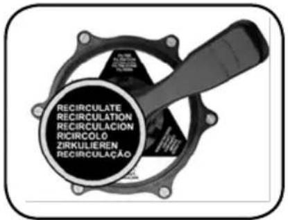
RECIRCULATE:
In this position, the selector valve allows the water from the pump to go directly to the swimming pool without passing through the inside of the filter.
WASTE:
If the swimming pool needs to be drained, this can be done using the filter pump. In order to do this, the selector valve should be in the "WASTE" position. The motor is run with the main drain valve fully open, for the pump to have sufficient suction. For the pump to suction, keep the prefilter and the main drain pipes full of water.
Before drainage, make sure that the skimmer valves and the bottom cleaner valves are closed.
RINSE:
After the carrying out the “BACKWASH” operation on the filter and placing the installation in the “FILTER” position, the water flowing into the swimming pool will be cloudy for a few seconds, so to prevent it from reaching the swimming pool there is a “RINSE” position for the selector valve which is operated as follows: immediately after the “BACKWASH” put the valve in the “RINSE” position and switch on the pump for 1 minute, after which the pump is switched off and the valve placed in the “FILTER” position. This position ensures that the filtered water goes directly to the drain.
CLOSED:
As its name indicates, this position is for closing off the water from the of the filter pump and it is used for opening the collector prefiltre of the pump.
MAINTENANCE:
Do not use solvents for cleaning the filter, this could damage the filter, especially its finish.
Always replace the joints and pieces that may not be in good condition. Backwash and rinse when needed, as per the instructions specified in this manual.
It's recommended to change the cartridge the filter approximately every 3 years.
CARTRIDGE ASSEMBLY:
If you replace a cartridge, you should proceed as follows. Thoroughly clean the inside of the cartridge and the seat of the seal in the cover assembly. Check that all parts are in a good state of repair, free of cracks and ble-mishes.
- Place the cartridge in its correct position. Gently press it downwards.
- Place the seal of the cover in its housing, subsequent to removing any traces of dirt in the housing.
- Tighten the screw on the cover as far as it will go.
- Once the cover assembly has been screwed in, follow the instructions in the Start-up section.
natural_image
Technical illustration of a mechanical component with layered structure (no text or symbols)10. WINTERISING:
At the end of the bathing season, it is recommended that the filter be emptied to prevent damage to its components. To do so, follow these steps:
- Stop the pump.
- Close the valves of the suction and discharge pipes in order to isolate the filter.
- Open the drainage cap of the pressure gauge on top of the filter.
- Open the pressure gauge at the bottom of the filter.
• Empty the filter completely.
• Disassemble the filter.
- Clean all dirt from inside the filter.
- Clean the cartridge if necessary using a hose.
- Store the cartridge in a dry place protected from frost.
- Cover the filter with a bag to protect it from water and sunlight.
- Empty all pipes to prevent them from bursting due to freezing.
11. TROUBLESHOOTING:
| PROBLEM CAUSE SOLUTION | ||
| Low filtration flow rate | Pump prefilter dirty Clean the prefilter | |
| Cartridge dirty Clean the cartridge | ||
| Pipe blocked Check valves, piping, etc. | ||
| Pump motors turn the wrong way round | Change the direction of rotation | |
| Pulsation of the pressure gauge | Air is entering the pump Repair any possible leaks | |
| Suction valve not fully open Open the suction valves | ||
| Rapid pressure increase | Cartridge dirty Clean the cartridge | |
| Algae in the pool Chemical treatment of the water | ||
| Cartridge dirty that has been used flocculant | Remove the filter cartridge and clean with pressure hose | |
| Water not clean enough | Chemical treatment unsuitable Change chemical treatment | |
| Cartridge dirty Clean the cartridge | ||
12. SAFETY WARNINGS:
- The persons who are in charge of assembly should have the required qualifications for this type of work.
- Comply with the current standards regarding accident prevention.
- In this regard, the UNE-EN 60335-2-41 standards must be observed: Household and similar electrical appliances - Safety - Part 2-41: Particular requirements for pumps.
- NEVER start up the system without water.
- NEVER allow children or adults to sit on the system.
- Do NOT connect the filter directly to the water network, as the pressure of the water may be too high and exceed the maximum work pressure allowed by the filter.
- Do NOT use the filtering circuit to fill and adjust the water level of the pool. A handling error may lead to overpressure in the filter.
- Do NOT clean the lid with solvents, as it may damage its properties (finish, transparency ...).
- As all the connections are made with joints, it is not necessary to tighten the nuts excessively in order to avoid that some plastic pieces could break.
- Do NOT use teflon in the T-part of the pressure gauge Kit, code 00545R0300, to ensure sealing.
- Do NOT use chemicals in powder form to treat the pool water as the filter could block up.
FRANÇAIS
natural_image
Mechanical pressure regulator device with pressure gauge and directional arrows (no text or symbols)natural_image
Close-up of a mechanical component with concentric rings and a central hub (no text or symbols visible)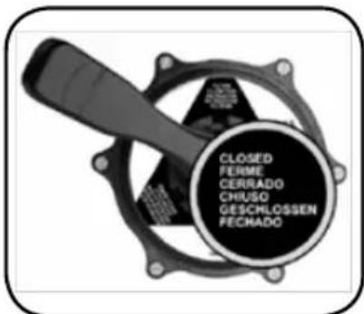
natural_image
Exploded view diagram of a mechanical assembly (no text or symbols visible)10. HIVERNAGE:
natural_image
Mechanical pressure relief device with pressure gauge and directional arrows (no text or symbols)- Montaje manómetro -
6. POSICIONAMIENTO DEL CARTUCHO:
natural_image
Close-up of a mechanical component with a cylindrical base and flange, showing internal concentric rings (no text or symbols visible)natural_image
Technical illustration of a mechanical assembly with layered components (no text or symbols visible)10. INVERNAJE:
natural_image
Mechanical pressure regulator device with gauges and adjustment arrows (no text or symbols visible)natural_image
Close-up of a mechanical component with a cylindrical base and a circular housing (no visible text or symbols)natural_image
Exploded view diagram of a mechanical assembly (no text or symbols visible)10. PERIODO INVERNALE:
natural_image
Mechanical component with pressure gauge and directional arrows indicating movement (no text or symbols)natural_image
Close-up of a mechanical component with a cylindrical base and a circular housing (no visible text or symbols)natural_image
Technical illustration of a mechanical assembly with layered components (no text or symbols visible)10. ÜBERWINTERUNG:
natural_image
Mechanical pressure regulator with gauges and directional arrows indicating movement (no text or symbols)natural_image
Close-up of a mechanical component with a cylindrical base and a flanged top, showing internal concentric rings (no text or symbols visible)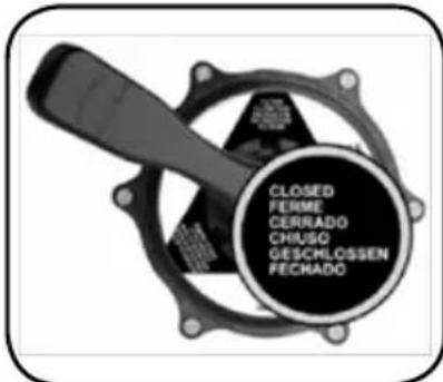
natural_image
Technical illustration of a mechanical assembly with layered components (no text or symbols visible)10. HIBERNAÇÃO:
| ID. CODE DESCRIPTION NanoFiber 150 NanoFiber 180 NanoFiber 200 Q. | |||||
| 1 6 | 4837-0013 Upper thread X X X 1 | ||||
| 2 6 | 7509 Cover assembly X X X 1 | ||||
| 3 8 | 070155026 O-ring seal shaft X X X 2 | ||||
| 4 6 | 4837-0550 Pressure gauge | X X X 1 | |||
| 5 6 | 4837-0150 NanoFiber 150 cartridge | X | 1 | ||
| 5 6 | 4837-0180 NanoFiber 180 cartridge | X | 1 | ||
| 5 6 | 4837-0200 NanoFiber 200 cartridge | X 1 | |||
| 6 7 | 7A2975070 Cover seal | X X X 1 | |||
| 7 6 | 4837-0540 Fastenings | X X X 1 | |||
| 8 6 | 4837-0003 Flange | X X X 2 | |||
| 9 6 | 4837-0015 Flange seal | X X X 1 | |||
| 10 | 64837-0530 Drainage cap assembly | X X X 1 | |||
| 11 | 00544-0106 Flat connection seals | X X X 2 | |||
| 12 | 65289 Adaptor sleeve | X X X 1 | |||
FRANÇAIS
| ID. CODE DESCRIPTION NanoFiber 150 NanoFiber 180 NanoFiber 200 Q. | |||||
| 1 64837-0013 Vis supérieure | X X X 1 | ||||
| 2 67509 Ensemble couvercle | X X X 1 | ||||
| 3 8070155026 Joint torique axe | X X X 2 | ||||
| 4 64837-0550 Manomètre | X X X 1 | ||||
| 5 64837-0150 Cartouche NanoFiber 150 | X | 1 | |||
| 5 64837-0180 Cartouche NanoFiber 180 | X | 1 | |||
| 5 64837-0200 Cartouche NanoFiber 200 | X 1 | ||||
| 6 77A2975070 Joint du couvercle | X X X 1 | ||||
| 7 64837-0540 Boulonnerie | X X X 1 | ||||
| 8 64837-0003 Bride | X X X 2 | ||||
| 9 64837-0015 Joint bride | X X X 1 | ||||
| 10 | 64837-0530 Ensemble bouchon de purge | X X X 1 | |||
| 11 | 00544-0106 Joints planches de branchements | X X X 2 | |||
| 12 | 65289 Manchon adaptateur | X X X 1 | |||
ESPAÑOL
| ID. | CÓDIGO | DESCRIPCIÓN | NanoFiber 150 | NanoFiber 180 | NanoFiber 200 | Q. |
| 1 6 | 4837-0013 Rosca | superior | X X X 1 | |||
| 2 6 | 7509 Conjunto Tapa | X X X 1 | ||||
| 3 8 | 070155026 Junta | torica eje X X X 2 | ||||
| 4 6 | 4837-0550 Manómetro | X X X 1 | ||||
| 5 6 | 4837-0150 Cartucho NanoFiber 150 | X | 1 | |||
| 5 6 | 4837-0180 Cartucho NanoFiber 180 | X | 1 | |||
| 5 6 | 4837-0200 Cartucho NanoFiber 200 | X 1 | ||||
| 6 7 | 7A2975070 Junta | Tapa | X X X 1 | |||
| 7 6 | 4837-0540 Tornilleria | X X X 1 | ||||
| 8 6 | 4837-0003 Brida | X X X 2 | ||||
| 9 6 | 4837-0015 Junta brida | X X X 1 | ||||
| 10 | 64837-0530 Conjunto tapon purga | X X X 1 | ||||
| 11 | 00544-0106 Juntas planas de conexiones | X X X 2 | ||||
| 12 | 65289 Manguito adaptador | X X X 1 |
DECLARATION CE OF CONFORMITY
The products listed above are in compliance with:
· Directive 2006/95/EC, on electrical equipment designed for use within certain voltage limits.
· Directive 2006/42/EC, on machinery.
· Directive 1997/23/EC, on pressure equipment.
- Directive 2014/30/EU, on electromagnetic compatibility.
· European Standards:
UNE-EN ISO 12100. Safety of machinery. General principles for design. Risk assessment and risk reduction.
UNE-EN 55014-1. Electromagnetic compatibility. Requirements for household appliances, electric tools and similar apparatus. Part 1. Issue.
UNE-EN 55014-2. Electromagnetic compatibility. Requirements for household appliances, electric tools and similar apparatus. Part 2. Immunity.
UNE-EN 60335-1. Household and similar appliances. Safety. Part 1. General requirements.
UNE-EN 60335-2-41. Household and similar appliances. Safety. Part 2-41. Specific requirements for pumps.
UNE-EN 61000-3-2. Electromagnetic compatibility. Part 3-2. Limits. Limits for harmonic current emissions (equipment input current ≤ 16 A per phase).
UNE-EN 61000-3-3. Electromagnetic compatibility. Part 3-3. Limits. Limitation of voltage changes, voltage fluctuations and flicker in public low-voltage supply systems, for equipment with rated current ≤16 A per phase and not subject to conditional connection.
DÉCLARATION CE DE CONFORMITÉ
Signature / Qualification:
Signature / Qualification:
Firma / Cargo:
Firma / Qualifica:
1 of January of 2017

Gerent
• TECHNICAL CHARACTERISTICS
• CARACTERISTIQUES TECHNIQUES
• CARACTERÍSTICAS TÉCNICAS
• DATI TECNICI
• TECHNISCHE ANGABEN
• CARACTERISTICAS TECNICAS
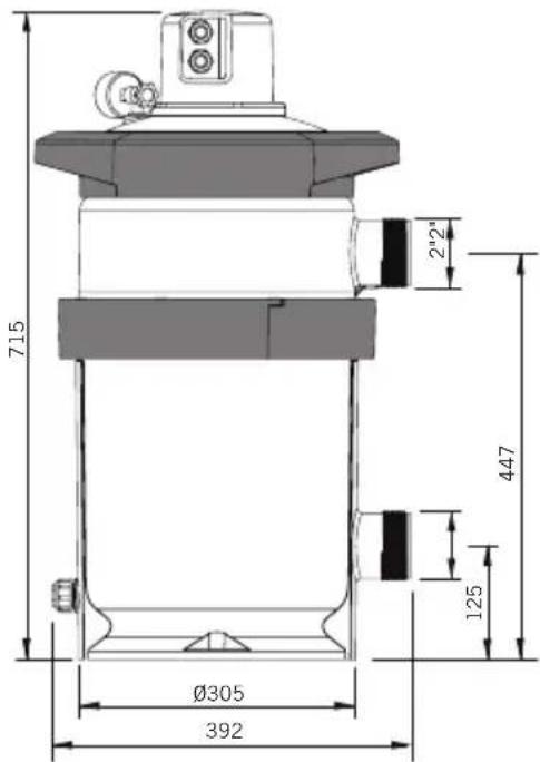
| Description | Filter NanoFiber | ||
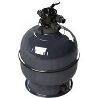
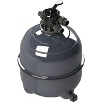
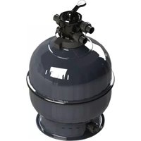
| 67355 67356 67357 | |||
| Flow / Débit / Caudal / Portata / Leistung / Caudal 10 m3/h | 14 m3/h 18 m3/h | ||
| Filtration area / Surface filtration / Superficie de filtración / Filteroberläche / Superficie de filtração | 4,5 m2 5,2 | m2 6,0 m2 | |
| Máximum working presure / Pression maximale de travail / Presión de trabajo máx. / Max. pressione di laboro / Max arbeitsdruck / Pressao maxima de trabalho | 2,5 kg/cm2 | ||
| Rated voltage / Tension nominale / Tensión nominal / Tensione nominale / Anschlusspannung / Tensão nominal | 220-240V 50-60 Hz | ||
| Standby consumption / Consommation en standby / Consumo en standby / Consumo in stand-by / Verbrauch in Standby / Consumo em standby | 0,3W (1,1VA) | ||
| Max. power / Puissance max./ Potencia máx. / Potenza massima / Max. leistung / Potência máx. | 8W | ||
| Protection / Protección / Protection / Schutz Protezione / Protectie / Protecção | IP55 | ||
| Weight / Poids / Peso / Peso / Gewicht / Peso 10,4 kg. | |||
\*67509
- ENGLISH
- General safety prescriptions:
- GENERAL SAFETY REGULATIONS.
- Any work to the filter and any equipment connected to it, must only be carried out when the start-up devices have been disconnected.
- ADVICE DURING INSTALLATION AND ASSEMBLY OPERATIONS.
- ADVICE FOR WHEN PUTTING INTO SERVICE.
- ADVICE DURING INSTALLATION AND MAINTENANCE WORK.
- CONTENT OF 67355-67356-67357:
- CONTENT OF 67509 KIT:
- GENERAL CHARACTERISTICS:
- INSTALLATION:
- The valve is sold separately.
- ATTENTION
- ASSEMBLY:
- POSITION OF THE CARTRIDGE:
- CONNECTION:
- IMPORTANTE:
- START-UP:
- FILTRATION:
- Example:
- BACKWASH:
- RECIRCULATE:
- WASTE:
- RINSE:
- CLOSED:
- MAINTENANCE:
- CARTRIDGE ASSEMBLY:
- WINTERISING:
- TROUBLESHOOTING:
- SAFETY WARNINGS:
- FRANÇAIS
- HIVERNAGE:
- POSICIONAMIENTO DEL CARTUCHO:
- INVERNAJE:
- PERIODO INVERNALE:
- ÜBERWINTERUNG:
- HIBERNAÇÃO:
- ESPAÑOL
- DECLARATION CE OF CONFORMITY
- DÉCLARATION CE DE CONFORMITÉ
- \*67509
Brand : ASTRALPOOL
Model : NanoFiber
Category : Water filter