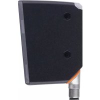
OPD100 - Photoelectric sensor IFM - Free user manual and instructions
Find the device manual for free OPD100 IFM in PDF.


User questions about OPD100 IFM
0 question about this device. Answer the ones you know or ask your own.
Ask a new question about this device
Download the instructions for your Photoelectric sensor in PDF format for free! Find your manual OPD100 - IFM and take your electronic device back in hand. On this page are published all the documents necessary for the use of your device. OPD100 by IFM.
USER MANUAL OPD100 IFM
CE
Operating instructions Photoelectric distance sensor
OPD100

Contents
1 Preliminary note....4
1.1 Symbols used ....4
1.2 Warnings used....4
2 Safety instructions ....4
3 Functions and features .... 5
3.1 General description ....5
3.1.1 Teaching and height profile....6
3.1.2 Normal operation....7
3.2 Interpretation of the matching value 8
3.2.1 Fluctuation of the matching value....8
3.3 Applications ......9
4 Function....10
4.1 Operating modes 10
4.1.1 Switching mode 10
4.1.2 Operation with IO-Link master.... 11
4.1.3 Operation with the Vision Assistant parameter setting software and an IO-Link master 11
5 Installation....12
5.1 Installation conditions 12
5.2 Installation instructions .... 12
5.2.1 Lateral inclination....12
5.2.2 Front inclination 13
5.2.3 Saturation and signal loss .... 13
5.2.4 Avoidance of multiple reflections .... 14
5.2.5 Avoidance of soiling and ambient light 14
6 Electrical connection....15
6.1 Operation with IO-Link master 16
7 Operating and display elements 16
8 Set-up 17
8.1 Guided Teach....18
8.1.1 Language selection 19
8.1.2 Teaching an object....19
8.1.3 Set ROI....19
8.1.4 Set the position of the reference profile....21
8.1.5 Switching threshold 22
8.1.6 Run mode....23
9 Menu....24
9.1 Basic functions ...... 24
9.2 Extended functions....25
10 Operating modes 27
10.1 Continuous mode 27
10.2 Triggered mode 28
11 Parameter setting....29
11.1 Parameter level basic functions....30
11.2 Parameter level extended functions....31
11.2.1 Submenu [Configuration]....32
11.2.2 Submenu [Display]....33
12 IO-Link 34
12.1 General information 34
12.2 Device-specific information....34
12.3 Parameter setting tools....34
12.4 Functions 34
13 Troubleshooting 35
13.1 Error indications in the display....35
13.2 Error indications in the "Vision Assistant" software....35
13.3 Other types of incorrect behaviour ....37
14 Maintenance, repair, disposal 38
15 Scale drawing 38
16 Factory setting 39
1 Preliminary note
1.1 Symbols used
▶ Instruction
▷ Reaction, result
[...] Designation of keys, buttons or indications
→ Cross-reference

Important note
Non-compliance may result in malfunction or interference.

Information
Supplementary note.
1.2 Warnings used

WARNING
Warning of serious personal injury.
Death or serious irreversible injuries may result.
2 Safety instructions
- Please read this document prior to set-up of the unit. Ensure that the product is suitable for your application without any restrictions.
- Improper or non-intended use may lead to malfunctions of the unit or to unwanted effects in your application. That is why installation, electrical connection, set-up, operation and maintenance of the unit must be carried out by qualified personnel authorised by the plant operator.
- In case of malfunction of the unit please contact the manufacturer. If the unit is tampered with and/or modified, any liability and warranty is excluded.

Caution - Use of controls or adjustments or procedures other than those specified herein may result in hazardous radiation exposure.
Position of the product label

Warning sign

3 Functions and features
3.1 General description
The sensor projects a laser line onto the object and determines the height profile of the object along the laser line by means of the triangulation principle.
The object to be detected has to be in the sensor's operating range.
The sensor has a trapezoidal operating range with the following dimensions:
• distance to the sensor (Z direction): 150...300 mm
• length of the profile (X direction):
- for an object distance of 150 mm: 45 mm
- for an object distance of 300 mm: 90 mm
ATTENTION
The unit may cause radio interference in domestic areas. In this case it can be necessary for the user to take appropriate measures.

1: X axis in [mm]
2: Z axis in [mm]
3: transmitter
4: receiver
5: ROI marking
Fig. 1

The projected laser line is wider than the operating range. The object to be detected should be positioned in the centre of the laser line.

For the factory setting the operating range is limited by two vertical ROI markings projected in green.
The ROI markings are not visible if the sensor is controlled via the "Vision Assistant" software.
3.1.1 Teaching and height profile
In the first step, the sensor is taught (teaching process). The entire height profile covered by the laser line is captured. The user can then further narrow the ROI.
- The height profile of this ROI is saved as taught reference profile.
In the next step, the sensor continually detects height profiles, compares them to the taught reference profile and generates a matching value. Now the user can set a switching threshold ( → 3.2).

1: X axis in [mm]
2: Z axis in [mm]
3: sensor
4: taught reference profile
Fig. 2
3.1.2 Normal operation
In normal operation, the sensor detects height profiles, continually or upon triggering, and compares them to the taught reference profile in order to generate a matching value.
If the "Vision Assistant" software is used, high-resolution images of the profiles are transmitted additionally ( → 4.1.3). The height profiles are referred to the max. measuring distance = 300 mm (reference height). The reference point for the reference height is the optical zero point of the transmitter. It is inside the sensor. Example: The distance between the sensor and the object is approx. 200 mm. In the "Vision Assistant" software, the height profile has a base height of approx. 100 mm.
- Profile heights are referred to the reference height and therefore have positive absolute values.
- All data sheet indications refer to the dimensions of the object profiles and not to the absolute distances between them and the sensor. The object profiles are displayed with real dimensions (object profile width/height) regardless of the object profile's position in the operating range.
3.2 Interpretation of the matching value
The measured height profile (in the following also referred to as "profile") is compared internally to a taught reference profile. The degree of match is generated as an internal measured value (matching value).
The measured value determined by the sensor hence describes the degree of match between the measured profile and the taught reference profile.
| Matching value provided in [%] | Description |
| 100 | There is a 100 % match between the measured profile and the taught reference profile. |
| 50 | There is a 50 % match between the measured profile and the taught reference profile. |

The matching value to be tolerated must be determined by the user during set-up and should be used as switching threshold for the following differentiation:
- good parts
- bad parts
The transition between good parts and bad parts is determined by measurement and used as switching threshold.

No particular switching threshold is recommended. It has to be determined according to the respective application.
3.2.1 Fluctuation of the matching value
Natural fluctuations (noise, drift) affect the measured matching value.
As a rule, these measurement fluctuations cause the matching value to be < 100%, even if the taught object is measured again.
The measurement uncertainty for the detection of height profiles is described using the following figures:
Gz - accuracy in Z direction (profile height)
Gx - accuracy in X direction (profile width)

1: sensor
2: measurement uncertainty
3: object profile
4: operating range
5: accuracy in Z direction (Gz)
6: accuracy in X direction (Gx)
Fig. 3
This means that Gz/Gx also defines the:
• minimum object height to be detected reliably
• minimum object width to be detected reliably

The height profiles are internally detected by the sensor with a higher resolution than Gz/Gx. Changes in object height/width can therefore be detected within the measurement uncertainty.
3.3 Applications
The photoelectric sensor is particularly suitable for process quality assurance, more precisely monitoring of workpiece shapes and fault detection.
Examples:
- Monitoring of the processing quality, e.g. diameters of drill holes.
- Check of workpieces for faulty processing, e.g. missing drill holes.

During the measurement, the workpiece has to be still.
- For static situations, the continuous measurement mode has to be set. The sensor permanently monitors the workpiece and signals deviations from the taught reference profile ( → 10.1).
- For dynamic situations, the triggered measurement mode has to be set. A higher-level process control unit decides when the detection takes place and ensures that the workpiece is in the detection zone and that it does not move ( → 10.2).
4 Function
The photoelectric sensor detects the height profile of the object in the operating range, continually or upon triggering, by means of triangulation. Besides, the photoelectric sensor has an IO-Link interface.
The sensor can be used in three different modes of operation:
- switching mode (→ 4.1.1)
• operation with an IO-Link master ( → 4.1.2)
• operation with the Vision Assistant via the IO-Link interface ( → 4.1.3)
4.1 Operating modes
4.1.1 Switching mode
In switching mode, the sensor is directly connected to the process control unit and transmits information on good part / bad part via the switching output.

If the set switching threshold is exceeded/not reached, this is signalled by means of switching signals on switching output 1/2. The switching outputs act complementary ( → 6 Electrical connection).
As an option, the time at which the measurement is taken can be controlled by a process control unit via the trigger input (pin 5). The sensor signals the successful start of the measurement and the availability of switching information via switching output 2. The higher-level process control unit defines the measurement period. ( → 10.2)
4.1.2 Operation with IO-Link master
If the sensor is connected to an IO-Link master, parameter setting, triggering and data recording can be done completely via IO-Link. The cyclic process data include the matching value and the switching information (good part / bad part).
Additional functions are available via IO-Link:
- detection of the number of trigger processes
- device identification

More information → www.ifm.com → Data sheet.
4.1.3 Operation with the Vision Assistant parameter setting software and an IO-Link master
Via the IO-Link protocol, high-resolution profile images are continually transmitted. The image data of a profile image is split up into several data packages and transmitted in a sequence of IO-Link data frames.
The ifm software package Vision Assistant includes a corresponding protocol handler that combines the profile images and visualises them.
This simplifies the teaching process (guided teach), as the detection zone of the sensor and the assessment of the profiles is visualised base on the profile images.
Prerequisite:
- IO-Link master
- ifm parameter setting software "ifm Vision Assistant" (E3D300)
Additional functions are available with the Vision Assistant software package:
- Overlay of the ROI in high-resolution profile images for a very precise setting.
- Extensive status information, useful in difficult measurement situations.

Visualisation of profiles can also be done using a customer-specific software. The information required for this can be found in the IODD.

More information → www.ifm.com → Vision Assistant.
5 Installation
5.1 Installation conditions
▶ Install the unit so that the object to be detected is within the sensor's detection zone.
▶ For direct installation, fix the unit using two M4 screws.

Further accessories → www.ifm.com → Data sheet → Accessories.
5.2 Installation instructions
5.2.1 Lateral inclination

1: dead zone due to shadowing
Fig. 4
The sensor should be aligned as vertically as possible to the object to be detected. In case of lateral inclination ( → Fig. 4) and vertical object edges, the laser line will be partially interrupted. The profile cannot be detected in this area. You can avoid this by reducing the inclination angle.
5.2.2 Front inclination

Fig. 5
If the sensor is inclined forwards or backwards, make sure that the laser line reflected by the object can be detected by the receiver → Fig. 5. It can be ensured that the receiver detects the laser line by reducing the inclination angle or rotating the sensor by 180° .

The use of the "Vision Assistant" software facilitates the detection of such problems.
5.2.3 Saturation and signal loss
The sensor automatically sets the exposure time for the capture of the height profile so that saturation is avoided.
Highly reflective surfaces lead to extreme contrasts. In some cases, this may lead to individual points within the ROI not being detected.
Avoid signal losses by slightly changing the sensor position:
• incline the sensor laterally or frontally
• increase or decrease the object distance
5.2.4 Avoidance of multiple reflections

1: sensor
2: object
3: multiple reflections
Fig. 6
▶ Slightly change the sensor position – e.g. incline the sensor laterally or frontally, increase or decrease the distance to the object.
5.2.5 Avoidance of soiling and ambient light
Preferably align photoelectric sensors with the front lens facing downwards or parallel to the earth's surface.
Background:
- Photoelectric sensors are sensitive to direct radiation of light sources. Everyday light sources (lamps, sun) radiate from above.
• Photoelectric sensors react sensitively to soiling, as it reduces the excess gain.

Dust deposits can be reduced by downwards or sideways orientation. This allows for longer cleaning intervals.

Make sure that sensors installed with their front lens facing upwards are not oriented towards roof windows or ceiling lamps.
6 Electrical connection

The unit must be connected by a qualified electrician.
▶ The national and international regulations for the installation of electrical equipment must be adhered to.
▶ Ensure voltage supply to EN 50178, SELV, PELV. OPD100: cULus, supply class 2
▶ Disconnect power.
▶ Connect the unit as follows:
| OPD100 PNP/NPN | |
 |  |
Core colours of ifm sockets:
1 = BN (brown), 2 = WH (white), 3 = BU (blue), 4 = BK (black), 5 = GR (grey).
| Pin | Continuous mode (factory setting) | Triggered mode |
| 1 | VDD | VDD |
| 2 | OUT2 = switching output | OUT2 = ready signal (switching output) |
| 3 | GND | GND |
| 4 | OUT1 = switching output / IO-Link | OUT1 = switching output / IO-Link |
| 5 | trigger input of the PLC | trigger input of the PLC |

In the operating mode "Continuous mode", OUT1 and OUT2 are configured as complementary switching outputs.(→ 10.1)
In the operating mode "Triggered mode", OUT2 is configured as ready signal. ( → 10.2).

Complementary outputs transmit the same sensor information with oppositional logic levels. This means that both an NC and NO switching output are available at the same time.
OUT1 can e.g. be used for the detection of good parts, OUT2 for the detection of bad parts.
6.1 Operation with IO-Link master
The unit is compatible with IO-Link master port class A (type A).

For operation with IO-Link master port class B (type B) observe the following:
As a standard, the unit is not compatible with master port class B (type B). Pin 2 and pin 5 are used for manufacturer-specific functions. That means that the main supply voltage of the unit and the additional voltage supply (master port class B on pins 2/5) are not electrically isolated.
With the following configuration the unit can be used with master port class B:
- Connect unit and IO-Link master via 3 wires: Connect pins 1, 3 and 4 of the unit with the IO-Link master (do not connect pins 2 and 5).
7 Operating and display elements

| 1: | 1x LED yellow | Switching status OUT1 |
| 2: | 1 x LED green | Active LED = power |
| 3: | Graphic display | Display of the measured matching value. |
| 4: | Programming button [ENTER] | Selection of the parameters and acknowledgement of the parameter values. |
| 5: | Programming button [Up] | Setting of the parameter values (scrolling by holding pressed; incrementally by pressing once). |
| 6: | Programming button [Down] | Setting of the parameter values (scrolling by holding pressed; incrementally by pressing once). |
8 Set-up
▶ After installation, electrical connection and programming, check whether the unit operates correctly.
▷ If the unit has been correctly set up, the sensor starts with the "Guided Teach" ( → 8.1). The settings made last are internally stored by the sensor.

When the sensor is switched on for the first time after a reset, it will also start with the "Guided Teach", as the taught reference profile is deleted in case of a reset.

Lifetime of a laser diode: 50000 hours.

After successful teaching, the sensor should not be moved again. Any change of the sensor position will lead to the taught reference profile not being recognised reliably. The sensor must be taught again if it has been moved.

The sensor needs a warm-up period of ≥ 10 min. The performance parameters specified in the data sheet only apply after this warm-up period. The teaching of objects should also be done in the warmed-up state.
8.1 Guided Teach
○ = [ENTER]
▲ = [Up] button
▼ = [Down] button
8.1.1 Language selection
▶ Put the sensor into operation.
▷ The available languages are indicated in the display.
▶ Select the desired language with the [Up] or [Down] button and confirm with [ENTER].
8.1.2 Teaching an object
In the next step, the profile is taught.
▷ The request [Place object and press confirm] is displayed.
▷ The sensor emits a red laser line with two vertical green ROI markings.
▶ Place the sensor so that the laser line covers the area to be monitored and the object is within the operating range of 150...300 mm → 3.1 → Fig. 1.
▶ Start the teaching process by pressing [ENTER].
▷ The sensor repeatedly measures the profile of the object/background.
▶ Select [Confirm] or [Back] using the [Up] or [Down] button and press [ENTER].
- [Confirm]: Taught profile is saved.
- [Back]: Teach the profile again.

The object should not be moved during measurement. The end of the measurement is not only indicated in the display, but also via the laser line flashing twice.

If the object to be detected is outside the operating range (e.g. closer than 150 mm or farther away than 300 mm), the teaching process is stopped. The message [Object out of range] appears for three seconds. Afterwards, a new teaching process is started.
8.1.3 Set ROI
The sensor makes it possible to select an ROI from the entire taught height profile. The profile section included in this ROI is saved as reference profile and used to determine the matching value.

Based on this restriction, the assessment of the height profile can be limited to the relevant section. Deviations regarding other, irrelevant sections are not taken into account.
In the next step, the ROI is set.
▷ The options [Define ROI] and [Back] are displayed.
▶ Select [Define ROI] or [Back] using the [Up] or [Down] button and press [ENTER].
- [Define ROI]: Define an ROI from the entire profile taught.
- [Back]: Teach the profile again.
| ▷ [Set left ROI mark] is displayed. ▶Move the green marking line using the [Up] or [Down] button. ▷ The left marking line shifts. ▶After reaching the requested position, confirm with [ENTER]. ▷ The position of the left marking line is set. ▷ The selected section is detected again (new profile). |  |
| ▷ [Set right ROI mark] is displayed. ▶Move the green marking line using the [Up] or [Down] button. ▷ The right marking line shifts. ▶After reaching the requested position, confirm with [ENTER]. ▷ The position of the right marking line is set. ▷ The selected section is detected again (new profile). |  |

Red line indicated in the display: represents the section covered by the laser line. White marking: represents the fixed marking line. Green arrow: represents the marking line to be moved.

The standard setting for the ROI includes the entire operating range. If the markings are not moved, but confirmed, the entire profile taught is used for assessment.
8.1.4 Set the position of the reference profile
In the previous step, a reference profile was taught from the ROI. In the next step, you can define the section in which the measured height profile is to be searched. There are two options:
Fixed:
The reference profile is searched in the ROI defined during teaching. As during teaching, the objects to be monitored must be positioned very exactly during operation.
Floating:
However, due to mechanical or manual shifting tolerances it is not always possible to position the object to be monitored the right way round. With the option [Floating], this problem can be avoided. The taught reference profile is searched across the entire detected height profile. The taught reference profile can be successfully detected along the X and Z axis despite a change in position.
Marking function: During teaching, the ROI is indicated via two vertical marking lines projected in green (ROI markings). This way, the user can see what section of the laser line is defined as ROI. After teaching has been finished, the marking lines disappear. However, they can be displayed manually ( → 11.1 Parameter level basic functions).
In the next step, the position of the ROI is defined.
▷ The options [Fixed], [Floating] and [Back] are displayed.
▶ Select [Fixed], [Floating] or [Back] using the [Up] or [Down] button and press [ENTER].
- [Fixed]: No shift of the object is permitted.
- [Floating]: A shift of the object in X direction (along the laser line) and in Z direction is permitted.
- [Back]: Return to → 8.1.3 Set ROI.
8.1.5 Switching threshold
In the next step, the switching threshold for the switching output is set. The standard setting is 90%.

1: matching value
2: switching threshold
▷ The sensor continually detects new height profiles and compares them to the taught reference profile.
▷ The matching value is shown in the display.

If matching value > switching threshold (standard = 90 %): measured value display is green → good part.
If matching value < switching threshold (standard = 90 %): measured value display is red → bad part.
Natural fluctuations (noise, drift) affect the measured matching value. As a rule, these measurement fluctuations cause the matching value to be < 100%, even if the taught object is measured again. ( → 3.2.1)
▷ The options [Adjust threshold], [Save settings] and [Back] are displayed.
▶ Select an option using the [Up] or [Down] button and press [ENTER].
- [Adjust threshold]:
▶ Set the value for the new threshold using the [Up] or [Down] button and press [ENTER].
- [Save settings]: Set-up is completed and the sensor is put to the Run mode.
- [Back]: Return to → 8.1.4 Set the position of the reference profile.

By testing several good parts / bad parts with different switching thresholds, the setting can be optimised for the application. The good part / bad part assessment is indicated in the display.
Use the extended functions to individually adjust the colour assignments. Standard: green value → good part / red value → bad part
8.1.6 Run mode
After set-up via a "Guided Teach", the sensor is put to the Run mode. The unit is ready for operation.
It continually detects profiles and compares them to the taught reference profile based on the set switching threshold.
The result (good part/bas part) is provided:
- Visually via the display:
- good part: matching value indicated in green if matching value ≥ switching threshold
-
bad part: matching value indicated in red if matching value < switching threshold
-
Visually via the switching status indication: colours according to the set function
- Switching output: Depending on the set function, OUT1 is switched or not switched.


In the status line of the display, the measurement state is indicated:
• Profile X: → undisturbed operation
- Warnings / errors: → see error table(→ 13 Troubleshooting).
9 Menu
9.1 Basic functions

○ = [ENTER]
= [Up] button
▼ = [Down] button
9.2 Extended functions

○ = [ENTER]
△ = [Up] button
▼ = [Down] button

○ = [ENTER]
▲ = [Up] button
▼ = [Down] button

○ = [ENTER]
▲ = [Up] button
▼ = [Down] button
10 Operating modes
10.1 Continuous mode
The default mode is the "Continuous mode".
The sensor continually measures and compares the measured profiles to the taught reference profile, taking into account the switching threshold.
10.2 Triggered mode
In this mode, the sensor starts the measurement after receiving an external trigger signal.
The sensor compares a single profile to the taught reference profile taking into account the switching threshold.
The external trigger signal must be provided by the higher-level process control unit (e.g. PLC) and can be transmitted physically via pin 5 or via IO-Link.
The sensor then signals the successful start of the measurement, and, a little later, the availability of the switching information via switching output 2 (ready signal) or IO-Link. The higher-level control unit has full control of the assessment time ( → Fig. 7).

Fig. 7
1: time
2: trigger signal
3: ready signal
4: switching signal
5: positive trigger edge / ready signal is reset
6: switching information is set
7: switching information is available (measurement terminated) / ready signal is set

This operating mode is particularly recommended for dynamic applications. The higher-level process unit only starts the measurement if the object to be detected does not move. The switching output corresponds to the object's status.
The [Trigger delay] delays the start of the measurement (referred to the external trigger signal). This does not affect / delay the ready signal provided by the sensor.
11 Parameter setting
During parameter setting the unit remains internally in the operating mode. It continues its monitoring function with the existing parameters until the change has been completed.
For the factory settings please refer to the end of these instructions ( → 16 Factory setting).
11.1 Parameter level basic functions
In the parameter level basic functions the following parameters can be selected:
| Parameter | Description |
| [Adjust Threshold] | Set the switching threshold▶ Confirm the parameter with [ENTER] and set the switching threshold to the desired value using the [Up] or [Down] button. ▶ Confirm the value with [ENTER]. ▷ The new switching value is confirmed. |
| [ROI Markings] | Activate/deactivate the indication of the ROI markings on the laser line If a [Fixed] position of the reference profile has been selected during teaching, the ROI markings show the ROI defined during teaching. If a [Floating] position has been selected, the ROI markings indicate the entire operating range (→ 8.1.4). ▶ Confirm the parameter with [ENTER] and select one of the options [NO] / [YES] using the [Up] or [Down] button. ▶ Confirm your selection by pressing [ENTER]. ▷ Depending on the setting made, the green ROI markings on the laser line are activated/deactivated. If a [Fixed] position of the reference profile has been selected during teaching, the ROI markings show the ROI defined during teaching. If a [Floating] position has been selected, the ROI markings indicate the entire operating range (→ 8.1.4). ▶ Confirm the parameter with [ENTER] and select one of the options [NO] / [YES] using the [Up] or [Down] button. ▶ Confirm your selection by pressing [ENTER]. ▷ Depending on the setting made, the green ROI markings on the laser line are activated/deactivated. No marking lines are indicated if the sensor is controlled via the "Vision Assistant" software. No marking lines are indicated if the sensor is controlled via the "Vision Assistant" software. |
| [New Profile] | Teach a new profile▶ Confirm the parameter with [ENTER] and select one of the options [NO] / [YES] using the [Up] or [Down] button. ▶ Select [YES] and confirm with [ENTER]. ▷ The existing profile is deleted. ▷ The sensor changes to the "Guided Teach". ▷ The message [Place object and press confirm] appears in the display. (→ 8 Set-up) |
| [Ext. Functions] | Change to the menu level of extended functions(→ 9.2 Extended functions) |
| [Back] | Finish parameter setting▶ Confirm the parameter with [ENTER]. ▷ The display changes to the Run mode. |
11.2 Parameter level extended functions
In the parameter level extended functions the following parameters can be selected:
| Parameter | Description |
| [Factory Reset] | Reset all parameters to factory setting▶ Confirm the parameter with [ENTER] and select one of the options [NO] / [YES] using the [Up] or [Down] button. ▶ Select [Yes] and confirm with [ENTER]. ▷ The sensor resets all parameters to factory setting and changes to the "Guided Teach". |
| [Device Info] | Sensor information▶ Confirm the parameter with [ENTER] and navigate through the information lines using the [Up] or [Down] button. |
| [Configuration] | Configuration of the operating mode and the switching outputs(→ 11.2.1)▶ Confirm the parameter with [ENTER]. ▷ The display changes to the configuration settings. ▶ Select one of the following options using the [Up] or [Down] button.1. [Trigger Mode]2. [Trigger Source]3. [Trigger Delay]4. [Integration Time]5. [Output Function]6. [Output Logic]7. [Back] |
| [Display] | Configuration of the display▶ Confirm the parameter with [ENTER]. ▷ The display changes to the display settings. ▶ Select one of the following options using the [Up] or [Down] button.1. [Brightness]2. [Colour]3. [Language]4. [Back] |
| [Back] | Finish parameter setting▶ Confirm the parameter with [ENTER]. ▷ The display changes to menu level 1. |
11.2.1 Submenu [Configuration]
| [Trigger Mode] | Set operating mode▶ Confirm the parameter with [ENTER] and select one of the options [CONT] / [TRIG] using the [Up] or [Down] button. ▶ Confirm your selection by pressing [ENTER]. ▷ The operating mode is confirmed. [CONT]: continuous trigger mode → 10.1[TRIG]: triggered mode → 10.2 |
| [Trigger Source] | Set the source for the trigger signal▶ Confirm the parameter with [ENTER] and select one of the options [HW] / [PDOUT] using the [Up] or [Down] button. ▶ Confirm your selection by pressing [ENTER]. ▷ The input signal is confirmed. HW: Apply the input signal via pin 5. The logic levels (npn / pnp) are defined under [Output logic]. PDOUT: The input signal is transmitted via the IO-Link master (IO-Link operation). |
| [Trigger Delay] | Set the delay time of the trigger signal until the start of the measurement▶ Confirm the parameter with [ENTER] and select the desired value (0...5000 ms) using the [Up] or [Down] button. ▶ Confirm your selection by pressing [ENTER]. ▷ The delay time is confirmed. |
| [Integration Time] | Set exposure time▶ Confirm the parameter with [ENTER] and select one of the options [Auto] / [0...10 ms] using the [Up] or [Down] button. ▶ Confirm your selection by pressing [ENTER]. ▷ The exposure time is confirmed.![IFM OPD100 - Submenu [Configuration] - 1](/content/2026/03/581970/images/d345fa2864628bb3bfd471ff2798dd0b7b09fd34f05ffd6e868edf6d481a8b2d.jpg) For the factory setting [AUTO], the exposure time is automatically determined and set by the sensor. A fixed setting of the integration time may be useful if a dark ROI situated amongst reflective surfaces is to be reliably assessed. For the factory setting [AUTO], the exposure time is automatically determined and set by the sensor. A fixed setting of the integration time may be useful if a dark ROI situated amongst reflective surfaces is to be reliably assessed. |
| [Output Function] | Setting of the switching function for OUT1▶ Confirm the parameter with [ENTER] and select one of the options [High active] / [Low active] using the [Up] or [Down] button. ▶ Confirm your selection by pressing [ENTER]. ▷ The output function for OUT1 is confirmed. High active: OUT1 is switched on if matching value > switching threshold. Low active: OUT1 is switched on if matching value < switching threshold. In the trigger mode [CONT], OUT2 is automatically set as complementary switching output to OUT1. |
| [Output Logic] | Set the switching logic for all inputs and outputs▶ Confirm the parameter with [ENTER] and select one of the options [PNP] / [NPN] using the [Up] or [Down] button. ▶ Confirm your selection by pressing [ENTER]. ▷ The switching logic is confirmed. |
| [Back] | Finish parameter setting▶ Confirm the parameter with [ENTER]. ▷ Display changes to [Configuration]. |
11.2.2 Submenu [Display]
| [Brightness] | Set display brightness▶ Confirm the parameter with [ENTER] and select one of the options [ON] / [OFF] using the [Up] or [Down] button. ▶ Confirm your selection by pressing [ENTER]. ▷ The display brightness is confirmed. |
| [Colour] | Set display colour for the matching value▶ Confirm the parameter with [ENTER] and select the desired option using the [Up] or [Down] button. ▶ Confirm your selection by pressing [ENTER]. ▷ The display colour for the matching value is confirmed. OptionsG1ou: green = good partr1ou: red = good partwhite: matching value always whitered: matching value always redgreen: matching value always green |
| [Language] | Select the menu language▶ Confirm the parameter with [ENTER] and select one of the options using the [Up] or [Down] button. ▶ Confirm your selection by pressing [ENTER]. ▷ The menu language is confirmed. |
| [Back] | Finish parameter setting▶ Confirm the parameter with [ENTER]. ▷ Display changes to [Display]. |
12 IO-Link
12.1 General information
This unit has an IO-Link communication interface which requires an IO-Link-capable module (IO-Link master) for operation.
The IO-Link interface enables direct access to the sensor values and parameters and provides the possibility to set the parameters of the unit during operation. In addition, communication is possible via a point-to-point connection with a USB adapter cable.
You will find more detailed information about IO-Link at www.ifm.com.
12.2 Device-specific information
You will find the IODDs necessary for the configuration of the IO-Link unit and detailed information about sensor values, diagnostic information and parameters in the overview table at www.ifm.com.
12.3 Parameter setting tools
You will find all necessary information about the required IO-Link hardware and software at www.ifm.com.
12.4 Functions
With IO-Link all functions and measured data are available that can also be accessed via the display and pushbuttons on the unit.
All functions are described in detail in the IODD.
13 Troubleshooting
13.1 Error indications in the display
| Display | Possible cause | Solution |
| Running | Sensor running in standard mode. There is no failure. | No need for action |
| Object out of range | Object is outside the operating range (too far / too close). No height profile and matching value can be determined. | Enlarge the distance to the object. The detected profile must be in the operating range 150...300 mm. |
| Short circuit OU1 | Short circuit in switching output 1. | Check the wiring. |
| Short circuit OU2 | Short circuit in switching output 2. | Check the wiring. |
13.2 Error indications in the "Vision Assistant" software
| Display | Possible cause | Solution |
| Low amplitude | The data points of the detected laser line have a very low intensity. | If all (352) data points are concerned:·Object is outside the operating range or is extremely dark. ▶ Check the distance to the object. If only a few data points are concerned:·Object features large differences in luminosity. Due to the characteristics of the object, some of the reflected laser beams do not reach the receiver. ▶ Change the position of the sensor or the object. |
| High amplitude | The data points of the detected laser line have a very high intensity. | In case of a fixed integration time: ▶ Reduce the time or change the setting to [Auto]. In case of large differences in luminosity: ▶ Change the position of the sensor or the object. |
| Laser line is too thick due to:- translucent surfaces such as skin, rubber- multipath propagation on shiny surfaces | ▶ Enlarge the distance to the object. ▶ Change the position of the sensor or the object. | |
| Multiple lines | Sensor receives several reflections due to:- semi-transparent objects, laser line is reflected at two planes- shiny surfaces on sharp profiles | ▶ Change the angle of incidence. If possible, darken the background. ▶ Change the position of the sensor or the object. |
| Too near / far | Data points outside the operating range in Z direction (< 150 mm, >300 mm) | ▶ Place the object within the operating range (150...300 mm). |

The profile images detected consist of 352 data points. Faulty data points are indicated as a dashed line in the "Vision Assistant". These data points are not used for determining the matching value.
The data errors and the number of data points concerned for the currently measured height profile are shown in the Vision Assistant. E.g.
Type of data error
Number of data points concerned
| Low amplitude | 5 |
13.3 Other types of incorrect behaviour
| Situation | Possible cause | Solution |
| Object cannot be taught."Object out of range" is displayed despite the object being in the operating range of 150...300 mm. | Due to the sensor being inclined frontally and the characteristics of the object / background, some of the reflected laser beams do not reach the receiver. | ▶ Slightly change the sensor position (front inclination, reduce/enlarge the distance to the object). ▶ If possible, rotate the sensor or the workpiece by 180°. |
| Sensor has been taught successfully. However, the matching value is very low (also for the taught object). | Sensor has been moved after teaching. Info: After a successful [Guided Teach], the sensor should not be moved again. Any change in position will lead to the taught reference profile not being recognised reliably. | ▶ Teach the sensor again. |
| Sensor has been taught successfully. However, the matching value is significantly lower than 90% for very similar workpieces. | The new workpieces may have slightly different surface characteristics, e.g. reflective surfaces. | ▶ Incline the sensor slightly frontally or laterally and teach it again. ▶ Or: check whether the width of the reference profile can be further limited. Then teach the sensor again. ▶ Or: manually adapt the [Integration time]. ▶ Or: reduce the switching threshold. |
| Sensor has been used for a while. Good parts are assessed to be bad parts. The matching value is below the set switching threshold. | Sensor has been moved unintentionally. | ▶ Teach the sensor again. |
| Front side of the sensor is soiled. | ▶ Clean the front side. ▶ If necessary, change the sensor position to avoid soiling and teach the sensor again. |
14 Maintenance, repair, disposal
Faulty sensors must only be repaired by the manufacturer.
▶ Keep the front lens of the sensor clean.
▶ After use dispose of the unit in an environmentally friendly way in accordance with the applicable national regulations.
▶ Do not open the module housing. There are no user-serviceable components inside.
15 Scale drawing


Dimensions in mm
1: programming buttons
2: colour display
3: transmitter
4: receiver
16 Factory setting
| Parameter | Setting range | Factory setting | Own setting |
| Threshold [%] | 0...100 | 90 | |
| Display of ROI markings in the Run mode | YES / NO | NO | |
| Operating mode (trigger mode) | CONT (continuous measurement) / TRIG (external trigger) | CONT | |
| Trigger source | HW / PDOUT | HW | |
| Trigger delay [ms] | 0; 10...5000 | 0 | |
| Integration time [step] | Auto; 1; 2...10 | Auto (automatically set by the sensor) | |
| Output function | High active Low active | High active | |
| Output logic | PNP / NPN | PNP | |
| Brightness | ON / OFF | ON | |
| Colour | G1ou; r1ou; White; Red; Green | G1ou | |
| Language | EN; DE; FR; ... | EN |
Technical data and further information at www.ifm.com
- 1 PRELIMINARY NOTE
- 1.1 SYMBOLS USED
- 1.2 WARNINGS USED
- 2 SAFETY INSTRUCTIONS
- 3 FUNCTIONS AND FEATURES
- 3.1 GENERAL DESCRIPTION
- 3.1.1 TEACHING AND HEIGHT PROFILE
- 3.1.2 NORMAL OPERATION
- 3.2 INTERPRETATION OF THE MATCHING VALUE
- 3.2.1 FLUCTUATION OF THE MATCHING VALUE
- 3.3 APPLICATIONS
- 4 FUNCTION
- 4.1 OPERATING MODES
- 4.1.1 SWITCHING MODE
- 4.1.2 OPERATION WITH IO-LINK MASTER
- 4.1.3 OPERATION WITH THE VISION ASSISTANT PARAMETER SETTING SOFTWARE AND AN IO-LINK MASTER
- 5 INSTALLATION
- 5.1 INSTALLATION CONDITIONS
- 5.2 INSTALLATION INSTRUCTIONS
- 5.2.1 LATERAL INCLINATION
- 5.2.2 FRONT INCLINATION
- 5.2.3 SATURATION AND SIGNAL LOSS
- 5.2.4 AVOIDANCE OF MULTIPLE REFLECTIONS
- 5.2.5 AVOIDANCE OF SOILING AND AMBIENT LIGHT
- 6 ELECTRICAL CONNECTION
- 6.1 OPERATION WITH IO-LINK MASTER
- 7 OPERATING AND DISPLAY ELEMENTS
- 8 SET-UP
- 8.1 GUIDED TEACH
- 8.1.1 LANGUAGE SELECTION
- 8.1.2 TEACHING AN OBJECT
- 8.1.3 SET ROI
- 8.1.4 SET THE POSITION OF THE REFERENCE PROFILE
- 8.1.5 SWITCHING THRESHOLD
- 8.1.6 RUN MODE
- 9 MENU
- 9.1 BASIC FUNCTIONS
- 9.2 EXTENDED FUNCTIONS
- 10 OPERATING MODES
- 10.1 CONTINUOUS MODE
- 10.2 TRIGGERED MODE
- 11 PARAMETER SETTING
- 11.1 PARAMETER LEVEL BASIC FUNCTIONS
- 11.2 PARAMETER LEVEL EXTENDED FUNCTIONS
- 11.2.1 SUBMENU [CONFIGURATION]
- 11.2.2 SUBMENU [DISPLAY]
- 12 IO-LINK
- 12.1 GENERAL INFORMATION
- 12.2 DEVICE-SPECIFIC INFORMATION
- 12.3 PARAMETER SETTING TOOLS
- 12.4 FUNCTIONS
- 13 TROUBLESHOOTING
- 13.1 ERROR INDICATIONS IN THE DISPLAY
- 13.2 ERROR INDICATIONS IN THE "VISION ASSISTANT" SOFTWARE
- 13.3 OTHER TYPES OF INCORRECT BEHAVIOUR
- 14 MAINTENANCE, REPAIR, DISPOSAL
- 15 SCALE DRAWING
- 16 FACTORY SETTING
Brand : IFM
Model : OPD100
Category : Photoelectric sensor