Power Heat Controler - Thermostat GYS - Free user manual and instructions
Find the device manual for free Power Heat Controler GYS in PDF.
| Product Type | Thermostat (smart box) for temperature regulation of ferrous parts |
| Brand | GYS |
| Model | Power Heat Controler |
| Power supply | Via the Powerduction generator (cable connection) |
| Temperature regulation range | 80 °C to 350 °C (in steps of 10 °C) |
| Adjustable heating power | 10% to 100% (default 50%) |
| Operating modes | Manual (pedal or trigger button); external regulation (PLC); with pyrometer |
| Sensor inputs | 2 thermocouples (type K); 1 analog pyrometer (0-5 V or current with shunt); input for external switch (pedal) |
| Display | Digital display on the Powerduction generator (highest temperature) |
| PLC interface | OK/Safety output (dry contact 5 A 30 V), Start input (dry contact) |
| Protections | Thermocouple fault detection, stop in case of sudden temperature drop |
| Maintenance and cleaning | Clean with dry cloth; dust with a blower after removing the cover; do not use solvents |
| Safety precautions | Disconnect before maintenance; risk of burns (do not touch hot parts); keep away from pacemaker wearers (≥1 m); remove metal jewelry |
| Authorized users | Children aged 8 and above under supervision; persons with reduced capabilities if instructions given |
| Warranty | 2 years (parts and labor), excluding transport, wear, misuse, environment; inductors and ferrites not covered |
| Compliance | CE, EAC, UKCA, Morocco (declarations available on website) |
| Country of origin | France (manufacturer address: 1, rue de la Croix des Landes, 53941 Saint-Berthevin Cedex) |
Frequently Asked Questions - Power Heat Controler GYS
User questions about Power Heat Controler GYS
0 question about this device. Answer the ones you know or ask your own.
Ask a new question about this device
Download the instructions for your Thermostat in PDF format for free! Find your manual Power Heat Controler - GYS and take your electronic device back in hand. On this page are published all the documents necessary for the use of your device. Power Heat Controler by GYS.
USER MANUAL Power Heat Controler GYS
FONCTIONNEMENT AVEC 2 THERMOCOUPLES (FOURNIS) (FIG I)
CONDITIONS DE GARANTIE
This manual contains safety and operating instructions, to be followed for your safety. Please read it carefully before using the device for the first time and keep it in a safe place for future reference. Read and understand the following safety recommendations before using or servicing the unit. Any change or servicing that is not specified in the instruction manual must not be undertaken. The manufacturer is not liable for any injury or damage caused due to non-compliance with the instructions featured in this manual. If there is any issue or uncertainty, please consult a qualified individual to operate the equipment correctly. This machine should only be used for operations comprised within the limits indicated on the machine and in the instruction manual. The operator must observe the safety precautions. In case of inadequate or unsafe use, the manufacturer cannot be held liable for damage or injury. Any other uses not specified in this manual is forbidden, and possibly dangerous. The product is semi automatic and requires the presence of an operator.
This unit can be used by children aged 8 or over and by people with reduced physical, sensory or mental capabilities or lack of experience or knowledge, if they are properly monitored or if instructions for using the equipment safely have been read and risks made aware of. Children must not play with the product. Cleaning and maintenance should not be performed by an unsupervised child.
Do not use the charger if the mains cable or plug is damaged.
Do not cover the device.

People wearing pacemakers are advised to not come close to the machine. Risk of disruption of pacemaker operations when close to the machine.
Consult a doctor before getting close to induction heaters.
Warning! Very hot surface. Risk of burns.
- The parts and pieces that have just been heated are hot and may cause burns when manipulated.
- Do not touch any hot parts with your hands.
- Wait for the parts and pieces to cool down before handling them.
- Check that jewellery (such as wedding rings) or other metal pieces do not get close to the induction heating machine or the inductor when switched on.
- Remove any jewellery or any metal object from yourself before using this machine
- People with metal implants should not use this machine.
- In case of burns, rinse with water abundantly and see a medical doctor as soon as possible.


Connection:
- This machine must be connected to an earthed socket.


Maintenance:
- If the power cable is damaged, it must be replaced by the manufacturer, its after sales service or an equally qualified person to prevent danger.
- Warning! Always disconnect from the mains before performing maintenance on the device. High Voltage and Currents inside the machine.
- Remove the casing on a regular basis, to remove any excess dust. Take this opportunity to have the electrical connections checked by a qualified person, with an insulated tool.
- Do not use solvents or any agressive cleaning products.
- Clean the device's surfaces with a dry cloth.
Regulations:
CE
Device complies with Europeans directives.
The certificate of compliance is available on our website.
- EAC Conformity marking (Eurasian Economic Community).
- Equipment in compliance with British requirements. The British Declaration of Conformity is available on our website (see home page).
- Equipment in conformity with Moroccan standards.
The declaration C_ (CMIM) of conformity is available on our website (see cover page).
Waste management:
- This product should be disposed of at an appropriate recycling facility. Do not throw away in a domestic bin.
- The product's manufacturer contributes to the recycling of its packaging by contributing to a global recycling system.
- This product should be recycled appropriately
GENERAL DESCRIPTION
The Powerduction Heat Controller is an intelligent box that acts like a thermostat on the Powerduction 110/160/220LG. It regulates the temperature of the part to be heated between 80^ and 350^ .
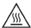
POWERDUCTION CONNECTION

- Disconnect the pedal from the Powerduction and then connect it to the Powerduction Heat Controller.

- Connect the product cable to the front panel of the Powerduction.
- The Powerduction Heat Controller is connected. Select an operating mode.
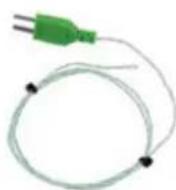
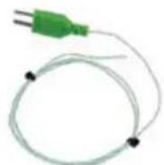
OPERATION WITH 2 THERMOCOUPLES (SUPPLIED) (FIG I)
Set the switch (8) to ON and press the heater enable button (9) (pedal activation). Connect the supplied thermocouples to the side of the interface:

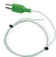
Thermocouples should be installed as close as possible to the area under the inductor ferrite.
It is recommended to drill the workpiece below the area to be heated with a drill bit of diameter 2 to a depth of about 1 to 2mm.
If switches (1) and (2) are in the OFF position, the Powerduction Heat Controller displays the highest measurement on the Powerduction 110/160/220LG.
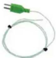
OPERATION WITH A PYROMETER (ref. 064119) (FIG I)
- Set switches (2), (7) and (8) to ON.
- Connect a thermocouple (supplied) to a thermocouple thermometer (not supplied).


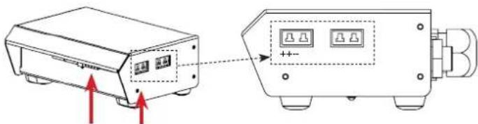
- Connect the pyrometer to the Powerduction Heat Controller (2 connectors)

When plugging the pyrometer, observe the connection direction of the thermocouple connector.
The positive terminal of the connector should be towards the front of the Powerduction Heat Controller, the negative terminal towards the rear.

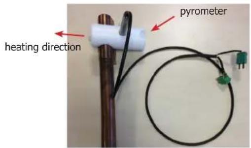
- Install the pyrometer on the Powerduction 110/160/220LG lance using the adapter and nylon screws provided.
- Install the thermocouple on the part to be heated as close as possible to the ferrite of the inductor (it is recommended to drill the part below the area to be heated with a 2mm diameter drill to a depth of approximately 1 to 2mm to insert the thermocouple).
Emissivity adjustment (while heating and staying in the same place on the workpiece)
- Turn the screw of the blue potentiometer (see wiring diagram) with a flat screwdriver 2.5 until the value displayed by the thermometer is identical to the value displayed on the Powerduction 110/160/220LG (+/-3^) .
- Once the setting has been made, remove the thermocouple from the piece to be heated.
Adjusting the emissivity is essential for a good measurement.
By turning the potentiometer clockwise, the displayed setpoint on the Powerduction 110/160/220LG will decrease and the temperature of the part to be heated will increase.
By turning the potentiometer anticlockwise, the displayed setpoint will increase and the room temperature will decrease.

It is advisable to point the heater in the opposite direction to the pyrometer location (see photo opposite).

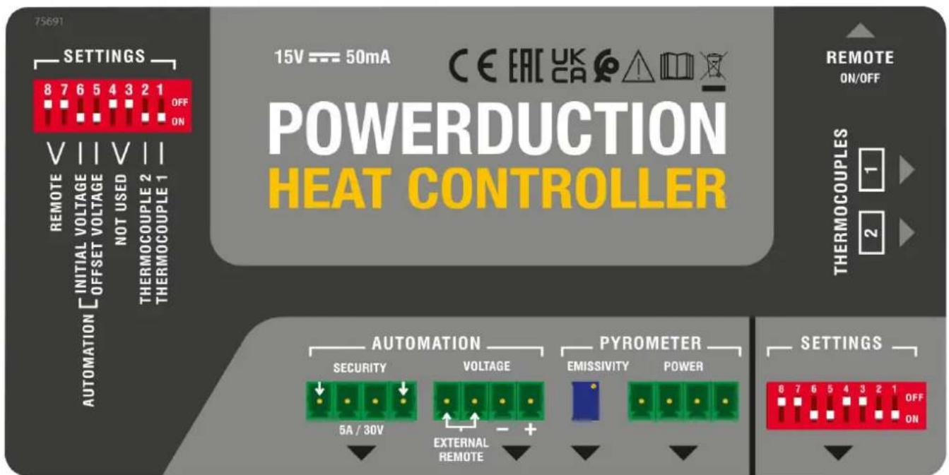
Connecting diagram
| Automation | Security dry contact |
| Voltage this connector allows you to connect a pyrometer to measure voltage or to connect an external switch (which replaces the pedal) | |
| Pyrometer | Emissivity This potentiometer allows to modify the setting (thanks to the screw) and to refine the temperature measurement according to the emissivity of the part to be heated. |
| Power this connector is used to connect the pyrometer (e.g. pyrometer - ref 064119) |
Switch setting
| 1 sif ON cancellation of thermocouple 2 measurement 2 if ON cancellation of thermocouple 1 measurement | { If both are OFF, the highest measurements is displayed. |
| 3 et 4 offline | |
| 5 if ON activation of an OFFSET for the initial display at 100°C (button 5 has priority over all the others) (do not use for a thermocouple measurement) | |
| 6 if ON and switch 5 OFF initial display at 0 (do not use for thermocouple measurement) | |
| 7 et 8 if ON activation of the footswitch connected to the REMOTE input |
OPERATION WITH PYROMETER ANALOG OUTPUT (not supplied)
Use a pyrometer sensor with an analog output directly on the product connectors (to be adapted according to the datasheet of the pyrometer used)
Example of a current measuring pyrometer

In this case, the value of the shunt R resistance on U T° must be adapted according to the setpoint and the desired accuracy (10 mV per Degree).
Correspondence table
| Voltage U T° Temperature in Celsius Temperature in Fahrenheit | ||
| 1 V 0°C 32°F | ||
| 2 V 100°C 210°F | ||
| 3 V 200°C 390°F | ||
| 4 V 300°C 570°F | ||
| 4.5 V 350°C 660°F | ||
MANUAL MODE (FIG II & III)

For an optimal use of the product, it is recommended to set the power between 30 and 50% .
To return to the «outdoor temperature control» mode:
- Press and hold the heating enable button (9) for 5 seconds.
- The button blinks every second and «rEG» is displayed.
The button on the lance (10) and the pneumatic pedal (11) are deactivated in this mode.
To set and then activate the heater :
- Adjust the control setpoint: Press the adjustment buttons (14). The regulation setpoint varies from 80^ to 350^ (default value at 250^ ) in 10^ steps. It is displayed for one second.
- Adjust the heating power setpoint (%): hold down the «Inductor change» button (13) and press the adjustment buttons (14). The heating power setpoint ranges from 10% to 100% (default 50%). The power is updated on the bar graph.
- Activate the heater: connect the pneumatic pedal (11) of the generator to the interface and press it. The minimum power light (12) flashes at 10Hz to indicate that the power is active.
It is possible to re-adjust the heater when it is active. In this case, it is not necessary to perform step 3. The heating in progress adapts to his new instructions.
AUTOMATION MODE (FIG II)
The product can be controlled by an automaton (see pin assignment) via the external interface.
To enter the «outdoor temperature control» mode (see pin assignment below):
- Switch on the product.
- Wait for the end of the start-up phase 5 s.
- Close the Start contact.
- Wait for the OK/Secur output to close (500 ms).
- Release the Start contact after detecting the OK/Secur.
- Check that the OK/Secure output remains closed.
The product enters the «external control mode» and generates a melody.
The heat enable button (9) and the LED on the lance button (10) flash once per second as long as the mode is activated.
To set the temperature setpoint and heating power: perform the same operation as in manual mode.
To activate the heater :
- Close the start switch. The product will heat until the set temperature is reached and regulated.
If the product detects a fault, then the OK/Secur output opens and the heater stops.
To acknowledge the fault, open the Start contact and press the heater enable button (9).
The product returns to «regulation» mode.
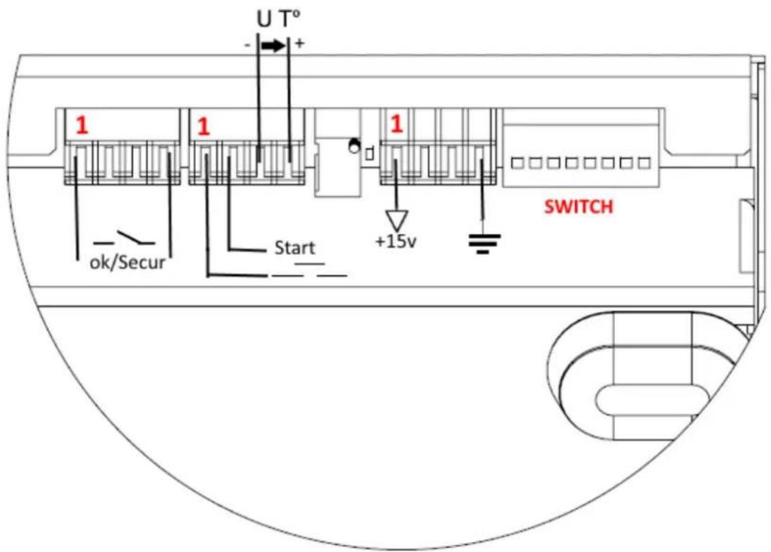
BROACHING

| Function No. of the wire | Type Electrical settings Values Logic | ||||
| Generator ready OK/Secur | 1/3 Digital output Type | Permissible direct current | Dry contact 5 A 30 V | Closed Ready-to-heat generator | |
| Opened Generator fault | |||||
| Earth 8 Earth Earth Terre Earth | |||||
| Start 9/10 Digital input Residual voltage (open circuit) Input impedance | 15 V 3.5 kΩ | Requires the use of a dry contact: a closed contact activates the heater. | |||
| Regulation voltage U T° | 11 - / 14+ | Analog input | Maximum input voltage | 5 V | Image input of the measured temperature. |
| Input impedance | 5.4 kΩ | See correspondence table | |||
| Accuracy | +/-5% | ||||
| Interface power | 12/13 | Continuous power supply | Output voltage | 15 V | |
| Output impedance | 100 Ω | ||||
DIAGRAM OF AUTOMATION START UP

SAFETY AND DEVICE FAILURE
- If the temperature input does not change after 5 s, the product is set to fault "E12".
- If a thermocouple breaks, then the regulation stops because the voltage U T^ exceeds the maximum voltage of 4.9 V.
- f the temperature drops significantly within a short period of time (e.g. when thermocouple probes go out of order), the heating stops and the product goes to fault "E11".
- In order to have the most accurate control possible, the measuring point(s) must be as close as possible to the inductor.
- This is the reason for the 2 thermocouples on the external interface.
- The display shows the highest temperature measured by the sensors.
WARRANTY
The warranty covers faulty workmanship for 2 years from the date of purchase (parts and labour).
The warranty does not cover:
- Transit damage.
Normal wear of parts (eg.: cables, clamps, etc.). - Damages due to misuse (power supply error, dropping of equipment, disassembling).
- Environment related failures (pollution, rust, dust).
In case of failure, return the unit to your distributor together with:
- The proof of purchase (receipt etc ...)
- A description of the fault reported
MODO MANUAL (FIG II & III)

He nCnoIb3yIte annapaT ecn ceTeBOJ shHyp nII BnIka NOBpeK-DeHbl.
He hakpbBaIte annapaT.

HocnteIe 3JIeKTPoKapDIOCTMMyJrTOPOB He DoJIxHbI npI6JIuXkaTb- cK aannapaty. PnCK c6oR pa6Otbl 3JIeKTPoKapDIOCTMMyJrTOPOB B6IIN annapata.
IpokohcylbTnpuYTecb y Bpaa nepeTdEm, KaK npn6JxKaTbcra K nHduknoHHOMy HarpeBaTeIIO.
BHMaHne! Topayar nobepxhoctb. Onachoctb oxkorob.
- Topnye DeTaIи Topyee o6OpyIOBaHne MOrYT BbI3BaTb OXoRn.
He doTpaRnBaI TeCb roJIbIMn pyKaMn Do HaRpeTbIX DeTaJe.
-Дождntecb,чTo DeTaHи OobopydOBaHne OCTbHyT npexde Yemdo HnX DoTpaRnBaTbcra.
CleIte 3a Tem, UTo6bI IOBeJIuHbIe YKpaUeHnA (B uactHOCTn, 6pUaJIbHbIe KOJIbua) nII MTeaJIInueCKne DeTaJIH He HaxOJINcB B6JIIN3n INdYKcUNOHHO CNTembl N INdYKTopa BO BpeMpa60Tbl.


- Chnmte c ce68 BCE IOBeIINpHbIe YKpaWeHnI n Dpyrne MeTaJIInueckne IpeMTeB I nepeD TeM, KaK NcNoJIb3OBaTb 3TO o6OpydoBaHne.
- IInca, IMeIoUne MeTaJIInueckNe IMnIaHTaTbI, He DoJXHbI NC- NOlb3OBA Tb 3TO O6OpyIOBaHne.
Bcnyae oXora,obnIbHo npOMoTe BODOn I npOKOHcyIbTnpuY Te Bpaa 6e3 npomeJenHna.
PoiKJIoueHne:
- 3TO yCTPOIcTBO DOJXHO 6bITb POKJIIOyeHO K PO3eTKe C 3a3emHeHnEM.
06cIyXnBaHne:
- Ecnn shhyp nHTaHn noBpeKdeH, OH doJxKeH 6bItb 3aMeHeH npOn3BOdnteIeM, eO cepBnCHO clyX60n nn KBaJIuΦnUnpoBaHHbIM CneuaJIInCTOM BO n36exKaHne ONaCHOCTN.
BHHMaHHe! OTKJIIOUHTe aannapat ot po3eTKn Do hauana peMOHTHbIX pa60T. - Perуларно OTKpbIbAite annapat n npOdyBaIte ero, yTO6bl OUnCTnTb OT nbIIN. Heo6xOdIMo TaKxe npOBepaTb BCE 3JIeKtpuYeCKne coeINHeHna C NOMOUsbIO N3OJInpOBaHHORO INHCTpyMeHTa. IpoBepka DoJIXHa ocUseCTBIArTBcR KBaIINΦNtIPOBaHHbIM cNeunAInCTOM.
- HN B KOem clyuae He nCnoJb3ObaTb paCTBOpNTeI INn dpyrHe Koppo3HbIe MOIOUne cpeDCTBa.
OuHCTIe NOBepxHOCTb aannapata c NOMOUsbO cyXoTpAKn.
Hopmbi npabnla:
- Annapat COOTBETCTByeT DnpeKtNBam EbpocoH3a.
-Декларачnia COOTBETCTBna ectb Ha Hauem caTe.
3HaK COOTBeTCTBnA EAC (EbpaaNCKoe 3KOHOmUeCKoe coo6ueCTBO).
MaTePnA1 COOTBeTCTByeT Tpe6OBAHnA M BeIiKo6pntaHn. 3aBHeHne O COOTBeTCTBnI DnA BeIiKo6pntaHn DoCTyNHO Ha HauWeM Be6-caITe (CM. IlaBHyIO CTpaHnCu). - Tobap COOTBeTCTByeT HOpMaM MapOKko.
-Декларачия C(CMIM)doctynha Дя сkaчваня Ha haшем caite (cM Ha TnTylbHоI CTpaHnCe).
YTNIN3aIGN:
- это оборудане полесит посяпотке. He вьбразытв вобши мycopocборнк.
AnnapaT, npo3BODntelb KOtOpOуyactByET B rIo6aIbHO npOrpamme nepepa60TKn ynaKOBKN, Bbl6OpOuHOn yTuIN3aUHN n pepepa60Tke 6bITOBbIX OTXODOB - 3TOT annapat noДeЖNT yTnIIn3aцn COrlaCHO NOCTaHOBJIeHNIO n°2014-1577.
ONHCAHNE
Powerduction Heat Controller ИИ КОТРОЛЕР HARPEBA Powerduction - ЗTO уMHь 6лOK, KOТOPьДеICTBYETΚАК Термocт ha Powerduction 110 / 160 / 220LG. Oh Perулирует Temпepатур oБогревамо злем enta, yctанавливая Powerduction мениу 80 °С и 350 °C.
IIOKJIIOUeyHNE K 3JEKTPONITAHNIO


- OToeHnHTe neaIb ot Powerduction, 3aTeM noKIOuHTe ee K Powerduction Heat Controller.

2.Подклочи Te Ka6eIb KoHTpoJIpepa K nepeDHeuЧаctn Powerduction.
3. Powerduction Heat Controller nooknueH Bb6epnte pexmu60tbi
PABOTAC2TEPMONAPAMN(IPNJIAGAETCA)(PNC.I)
UctaHOBnTe nepeKIOuateIb (8) B noLoXeHne ON n HaxMITE KHOJky ABTOpHaZauH HarpeBa (9) (akTNaunna pea). IopKnIOuHTe TepMonapbl, npedycMOtpeHHbIe Ha 6okoboi nobepxHocn INHTeppeica:


TepmonapbldoJHKbI 6bITb yCTaHOBJIeHb KaK MoXHO 6JIHXe K 3OHe NOI INHdyKTOpOM feppNTa. PekomeHnyETcB cBePnITb DeTalb YyTB HIXe 3ObHb HArpeBa C NOMOuBIO CBepJa DnAmEtPOM 2 Ha rIy6NHy OT 1 Do 2 MM. EcnI nepeKluoateNl (1) n (2) HaxOJaTcB B NoLoXeHHN «OFF.》,Powerduction Heat Controller no3BoJrE TTo6paKaTb camoe BvICOKOE n3MepeHne Ha Powerduction 110 / 160 / 220LG.
PABOTAC INPOMETPOM (nCX.064119) (PNC.1)
- YctaHOBInTe nepeKIOuOaTeINn (2), (7) n (8) B noLoXeHne ON
2.ПодсоeДинTe TepMonapу (npnlaraetc) K TepMometpy C TepMonapoi (He npnlaraetc)

- Побкюнтейnpomotр к Powerduction Heat Controller (2 pa3bema)

Ppi noKJIuOHeHn HnpMeTpa co6IIOaJTe HnPaBLeHne noKJIuOHeHna pa3bema TepMonapbl.
IIOJXNTeHbBb BbIBoD pa3bema DOJKeH 6bITb HApPabHeN K IpeHHe N acTn PHC, OTpuataJIbHbB bIBOd - Ha3a.

- YctaHOBInTe npomepHa HacaKy Powerduction 110 / 160LG / 220LG, nCnoIb3yra npnlaerae bte aanTep n HeJIOHOBBIE BnHTbl.
- YctaHOBtTe TepMonapy Ha HarpeBaemyo DeTaJIb KaK MoXHo 6JINKe K feppHTy INdyKTopa (peKOMeHnyETcB CBePInTb DeTaJIb HIXe 3OHbI HarpeBa C NOMOuBIO CBepLa DnAmEtPOM 2 Ha rIy6Hne IprImepHO OT 1 Do 2 MM, UTo6bl BCTaBtB TepMonapy)
PerynpoBka Ko3ofoeHt a3nyeHn (npn HarpBaHH nTeTn, OCTaBaacb B ODHOM NIOXKeHN)
- Поворачивайтсинь ВИТН ПОТЕЦИМЕТра (СM. Схему NOДКЛЮЧЕНИ) C NOMOДБЮ ПLOСКОI OTВЕРТКI 2,5,пokaЗачEHNE,OTOBpaЖаEMOE TepMOMeTpOM,He 6удET paBHO 3HAueHIN,OTOBpaЖaEMOMy Ha Powerduction 110 /160LG (+/- 3°C).
- Iocne perynipOBKn OTcoeHNHTe TepMonapy OTHarpeBaem DeTaJI.
Perynpobka K03ΦnueHtA n3nyeHn Heo6xoDnMa dI npabnlbHoro n3MepeHn.
Pn nobopoTe noTeHcHmOeTp a no YacOBo CTpeJIke 3aHaHHoe 3HaueHne, OTo6paKaemoe Ha Powerduction 110 / 160LG, yMeHbIHTcra, a TempePaTypa o6OrpeBaEMoro 3JeMaHNTca.
Ipn nobopoTe noteHcHOMeTpapnoTb uacOBn CTpeKN OTo6paKaemoe 3aHaHHe 3aueHne 6ydet yBeHNuBaTbcra, a TemnpaTypa oBorpeBaemoro 3nEmeHTa 6ydet CHXkTaBC.

KeIaTeJIbHO opHeHTnpoBaTb HarpeBaTeJb B npOTnBONIOXHom HappaBHeH N OT MeCTa pacNoIoxeHH NpOMeTp a (cM. FOTO HApOTnB)

Cxema coeHHenH
| Automation | Security Kontraktetc. |
| Voltage àTOT pa3bem NO3BOJAEТ NOДКЛIOCHITь ПИРOMeTp ДЯ ИЗМЕЧЕНУЕпRIОПКЛIOUCHITь ВHESHNII BByKЛIOUaTeJIb (KOTOPbI 3aMeHЯET peDAJIb) | |
| Pyrometer | Emissivity àTOT noTeHцINOMeTp NO3BOJAEТ ИЗМЕHTь NaCTpoIky (6laRODAPY BIVNTy)ИУTOHITь ИЗМЕРЕNHе TempepaTUpI B COOTBeTCTBn C I3JIyauTeJIbHOICNoCoBHoCTbIu HarpeBaEMoro ΕIeMeHToA |
| Power àTOT pa3bem ИСПОЛБ3уETСДЯ NOДКЛIOUчЕНУЕпИРOMeTpRa (HAN: ПИРOMeTp -apr 064119) |
Hactpoika KomyTaTopa (CBN)
| 1 éсn ON otmeha n3mepenra Tepmonapb 2 2 eon ON otmeha n3mepenra Tepmonapb 1 | Ecni oba OFF, oTo6pkaeHne camoro BbICOKOr n3mepenry |
| 3 et 4 He nodkloucen | |
| 5 eon ON. OFFSET akTbRpoBaHO對於 naalbHoro oTo6paXeHnra prn 100 °C (KhoIka 5 mceT prnoiTeT nad BCemn ocTaIbHbIMN) (He nCpOJIb3yIte對於 n3mepenra C TepmonapoY) | |
| 6 eon ON BkIoucen I eon nepeKloucaTeB 5 BbIKloucen, naalbHoe 3NaueHne 0 (He ncPONb3OBA Tb對於 n3mepenra C TepmonapoY) | |
| 7 et 8 eon ON akTbBaunr peDalln, noDkIoueHHoN K YDAJIENHOMY BxOdy |
PA6OTA C AHAJIORObbIM BbIXOHBIM INPOMETPOM (He BXoNTB KOMJIeKT)
IcnoB3yIe DaTnK NipomEtpa C aHaIorOBbIM BbIXoDm HEnocpeICTBeHHO Ha pa3beMax npOdykTa (Ira aanTaunn B COOTBECTBnC Ta6nuei NcNoB3yeMOrO NiPOMeTp)
PYHON PEKIMM (PNC II I III)

Длг ONТмальогинспльбзованяnpodyктapekomeHyetcyaCTaHabnBaTb3HaueHneMoцноTOn30 do 50%
Для BXOda B peKIM «perylnpoBaHne HapxHoi TemnepaTpybI»:
- YdepxkBaIte HaxKaToN KHOIpKy ABTOp3aunn HarpeBa (9) B TeueHne 5 cek.
- Khonka miraet Kaekdyu cekhy, n oTo6paKaetc «rEG».
B 3TOM pexime KhoNka Ha hacaKe (10) nHneBMaTnuecka neJaIb (11) oTKIOUeHbl.
YTO6bI yCTaHOBnTb n AKTHBnPOBaTb HaPeB:
- OtperynpyTe 3NaueHne perynuPoBaHna: HaxMnte KhoNk nperynnpOBKn (14).
3NaueHne perynilpoBaHnHa 3MeHaeTcra O T 80^ do 350^ (3naueHne no ymoJuaHIO npn 250^) c 7arom 10 C. OTo6paXaEeTcB TeueHne 1 cek. - YctahOBHTe 3aHaHHoe 3HaueHHe MoUHocTn HaPeBa (%) : ydepxNBAite KhoNky «CmeHa nHykTopa» (13) n HaxMMTe KHOKN peYIINPOBKn (14). 3HaueHHe MoUHocTn HaPeBa BapbIpyetc rO 10% do 100% (3HaueHne no yMOJIuaHIO COCTaBJIeT 50% ). MoUHocTb o6HOBJIeTcra Ha INTOrpamme.
- AKTINBaCnHaRpeBa: NOKJIIOHcTe nHEBMaTnueckyIO neaJIb (11) reHepaTopa K INHTepeCy n HaxMnte Ha Hee. INdNKaTOP MInHMaJIbHOm MOUHcTo (12) mraet c uactoToI 10 T, yKa3bIba r Ha To, YTO nITaNHe aKTINBHO.
Moxho nobTOpHO OTPerynipoBaTB HarpeB, KOrda OHO aKTHNBHO. B 3TOM clyuae HeT Heo6xoDmOCTN BbIIOJIHrTa
- Tekyün Harpeb aadantnpyeTcno HOBblHOBBIM 3HaueHnra.
ABTOMATUÇECKM PEKIM (PNC II)
Moxho ynpabTb annapaTOM uepe3 PIK (cm.pacnHOBky) uepe3 BHeHn HHTepfeic.
YTo6bI BoiTu BpeXm «PeryunpoBaHne TemnepaTypbI HapyXHorO Bo3dyxa» (CM. paCnHHOBky HnKe):
- BkIIOUHTe npOdyKT.
2.Дождпесь Okончаня pha3bl 3anycka 5c. - 3akpoTe KOHTaKT Start.
4.Дождпесь зakргия Выхда OK / Secur (500 Mc). - OTnycTe KOntaKT Start nocJe 6hApyKeHn OK / Secur.
- Y6eIntecb, yTO BbIXoOk / Secur ocTaeTcra 3aKpbITbIM.
IpoDyKT BxOaNTB «peXIM BHeUHero peYunIpOBaHnra» I BOCpOn3BOoNT MeIoAnIO.
KhoKa aBToPi3aunn HArpeBa (9) n CBeToIOoN KHOKn HacaKn (10) MInraOT OOnn pa3 B CekyHdy, Noka BKlOueH peXIM.
Yto6bI 3aadTb 3Naehne TemnepaTypb I MouHocTb HarpeBa: BblIOJIHNTe TY Xe OepaUIO, YTO IN B pyHOM peKIMe.
YTo6bI aKTbHbPoBaTb HaPeB:
- 3akpoTe KOHTaKT Start. PpOdyKr HArpeetc, yTo6bl DoCTmMb N OTPeRyIuPObaTb 3aDaHHyIO TeMnepaTyPy.
Ecn npoyKT 6hApynBaet HncnPabHocTb, OTKpbIaEcTc BbxOd OK / Safe n HarpeB npeKpaauetca.
YTo6blncnpaBntb Own6Ky,OTKpoTe KOHTaKT Start n HaxMnte KhoNky ABTOp3aunn HarpeBa (9).
Annapat Bo3BpaaetaeTcBpeKIM «perylinpoBaHnIg
PACINHHOBKA
BE30NACHOCTb HENCNPABHOCTb YCTPOICTBA
-
Ecnn BxOdnHae TemnepaTpya He n3MeHReTcB TeueHne 5 c, npoDyKT BbIOdnt Oun6ky «E12».
-
Ecn Tepmonapa o6pe3aetc, perynipobAHne npekpaaaetc, nockolky HapjxHne UT npebbuaet MaKcmaHoe HapjxHne 4,9 B.
-
Ecn TemnepaTpya 3NaHTeJbHO NaaET B TeHHeN KOpOTKOro BpeMeHN (HaPmEp, KOrda DaTUnKn TepMonapbl NaaHO), HArpeB npeKpaAaeTcR, i npOdyKT nepExoDIT B HeNCnPabHocTb «E11».
-
4To6bI o6ecneuHb MaKcImaJIbHO ToUHoe peRyJInpOBAHHe, ToUKN I3MepeHnA DoJXHbI 6bITb KaK MoXHo 6JIxKe K INdyKTOpY.
-3To npuHnHa dIy 2 Tepmonap Ha BHeuHem INHTepfeiece.
- Ha dinclnee oTo6paxaetc cama BbICOKa TeMpepaTpa, n3MepeHHa DaTuHKaM.
TAPAHTR
TapaHTn paCnpocTppaHreTc H Na IIO6o3aBODCKO DeΦeKT NIIb 6paK B TeueHne 2x Jnt C DaTbI NOKynKu N3dEInr (3anYactn n pa6oay cna).
TapaHTnHe pacnpoctpaHReTcHa:
JIIO6bIe NOLOMKn, BbI3BaHHbIe TpaHcNtOpTnpOBKOJ.
- HopMaJIbHbI n3Hoc dTeTaeNei (HaNPmEp : ka6eJI, 3aXnMbI n T.d.).
CnyuHn HnpaBnBHO NOIb3OBAHn (oW6Ka nTaHn, naeHne, pa36Opka).
Cnyuany Bixoia n3 cTPOI 3-3a Okpykaioe Cpebl (3aqr3HeHne BO3dyxa, Kopp03n, nbIb).
PnBbIXOe n3 cTpo, o6paNTecb B NYKTK NOKyKN AnnapaTa C npdeBraHHeHcneDyUoXN DOkyMeHTOB:
- DOKyMeHT, NOBtBePkaIOUIN NOKyNk (c DaToI): Kaccobbl YeK, INBOIn...
-ONICAHNE NOJOMKN.
BELANGRIJKE VEILIGHEIDSINSTRUCTIES