
AC2520 - Electronic module IFM - Free user manual and instructions
Find the device manual for free AC2520 IFM in PDF.
| Product type | AS-i electronic module |
| Model | AC2520 |
| Brand | IFM |
| Power supply | Via AS-i bus (24 V) |
| Pt100 measuring range | -200 °C to 850 °C |
| Resolution | 0.1 °C |
| Conversion time (4 channels) | 480 ms |
| Total transmission time (4 values) | Approx. 620 ms |
| Maximum number of modules per AS-i network | 31 |
| AS-i profile | S-7.3.E |
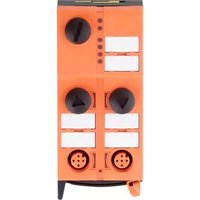
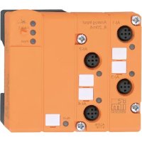
| Sensor connection | M12 connectors (2-wire or 4-wire) |
| Adjustable parameters | 50/60 Hz filter, enable device fault per channel, 2/4-wire selection |
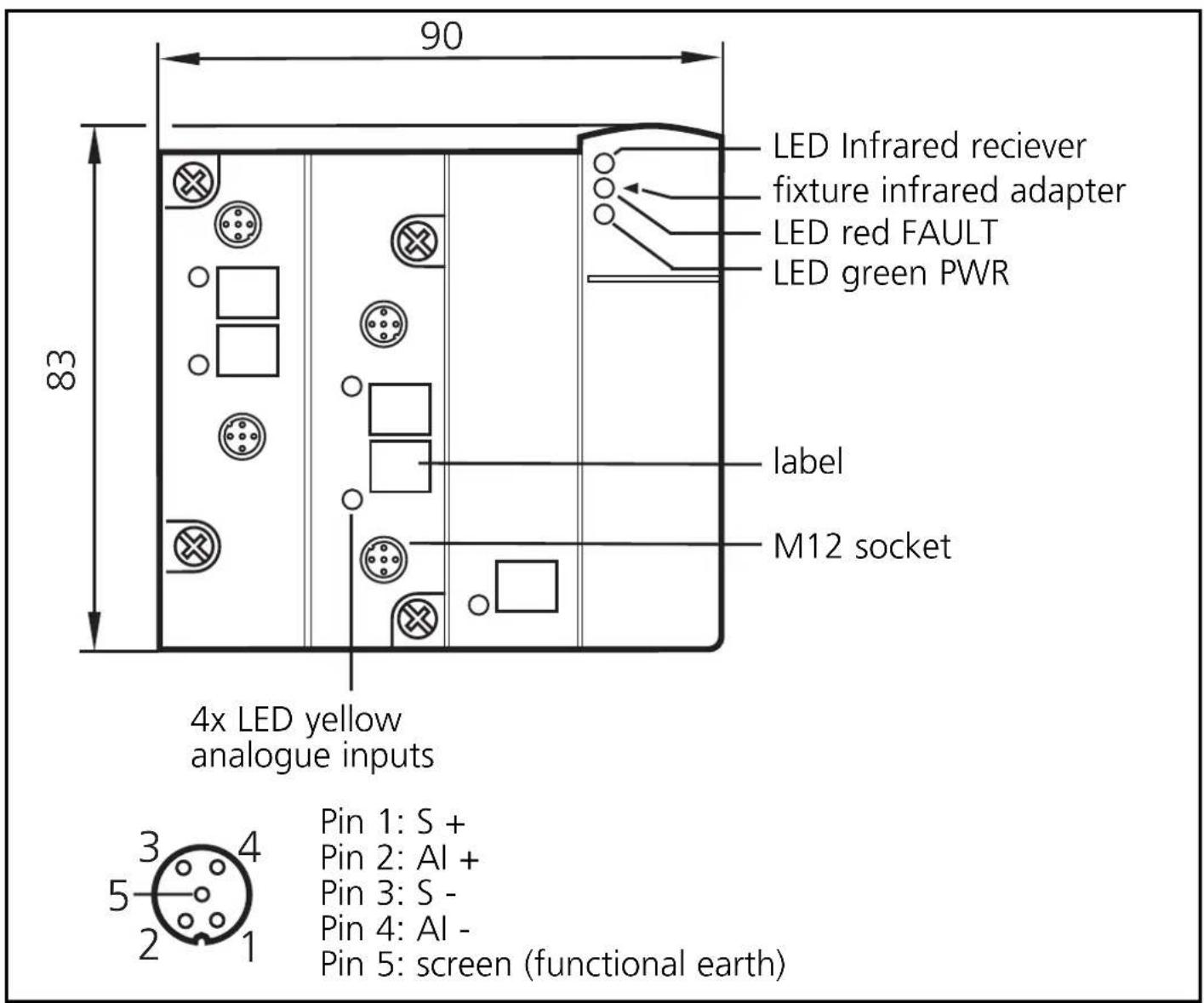
| LED display | 4 yellow LEDs (analog channels), 1 green AS-i PWR LED, 1 red FAULT LED |
| Dimensions (approx.) | 50 x 50 x 30 mm |
| Weight (approx.) | 100 g |
| Maintenance | Clean with a dry, lint-free cloth |
| Safety | Follow the instructions in the manual; disconnect power before maintenance |
| Repairability | Repair by manufacturer only |
Frequently Asked Questions - AC2520 IFM
User questions about AC2520 IFM
0 question about this device. Answer the ones you know or ask your own.
Ask a new question about this device
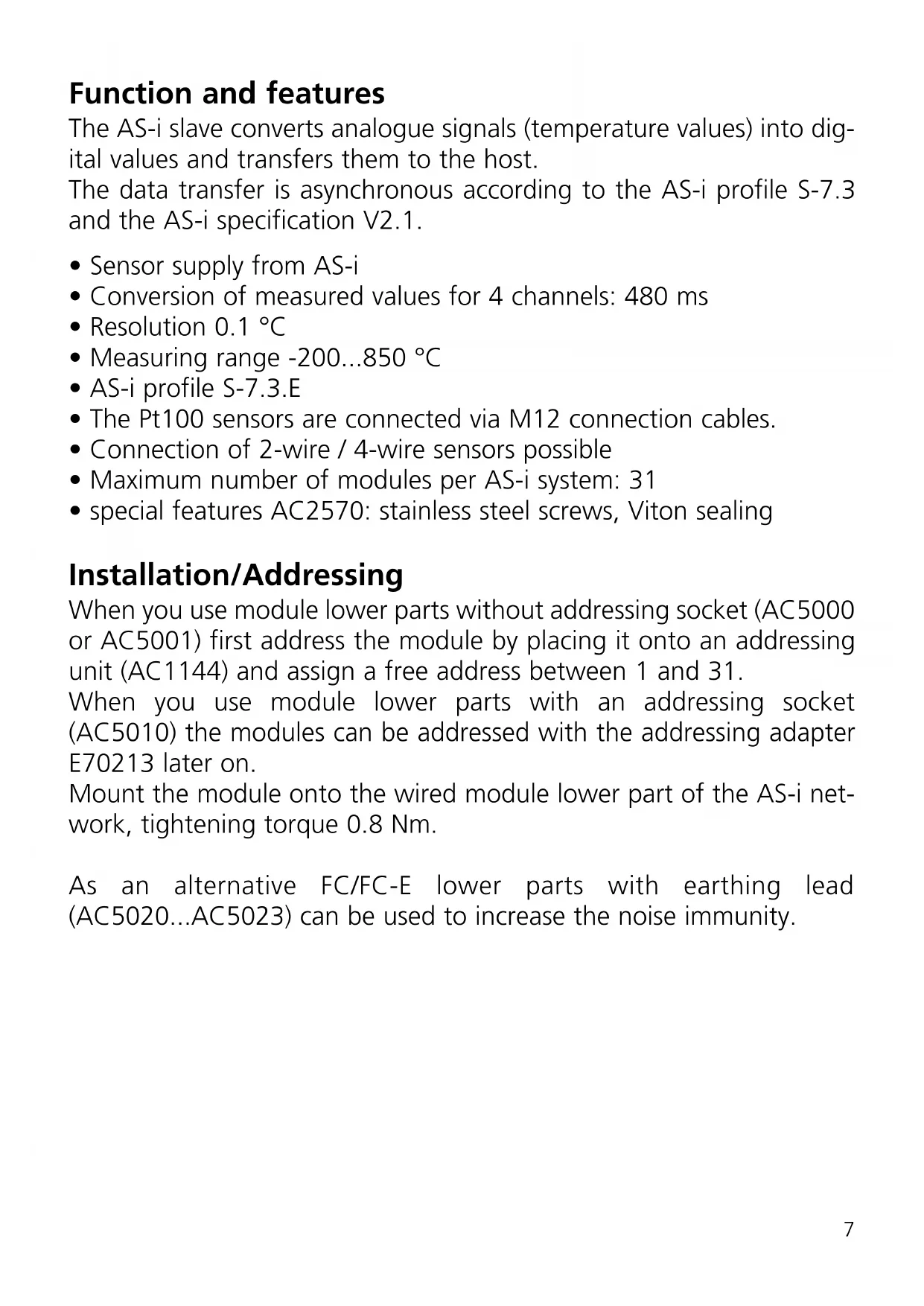
Download the instructions for your Electronic module in PDF format for free! Find your manual AC2520 - IFM and take your electronic device back in hand. On this page are published all the documents necessary for the use of your device. AC2520 by IFM.
USER MANUAL AC2520 IFM
Function and features
The AS-i slave converts analogue signals (temperature values) into digital values and transfers them to the host.
The data transfer is asynchronous according to the AS-i profile S-7.3 and the AS-i specification V2.1.
- Sensor supply from AS-i
- Conversion of measured values for 4 channels: 480 ms
- Resolution 0.1^ C
- Measuring range -200...850 °C
AS-i profile S-7.3.E - The Pt100 sensors are connected via M12 connection cables.
- Connection of 2-wire / 4-wire sensors possible
Maximum number of modules per AS-i system: 31 - special features AC2570: stainless steel screws, Viton sealing
Installation/Addressing
When you use module lower parts without addressing socket (AC5000 or AC5001) first address the module by placing it onto an addressing unit (AC1144) and assign a free address between 1 and 31.
When you use module lower parts with an addressing socket (AC5010) the modules can be addressed with the addressing adapter E70213 later on.
Mount the module onto the wired module lower part of the AS-i network, tightening torque 0.8 Nm.
As an alternative FC/FC-E lower parts with earthing lead (AC5020...AC5023) can be used to increase the noise immunity.
Electrical connection
The analogue module is connected to the AS-Interface via the standardised EMS [(supply from AS-i) (also in this case the Pt100 sensors are supplied from the AS-i voltage)].
For all the following wiring diagrams the indicated pin connection refers to the analogue module.
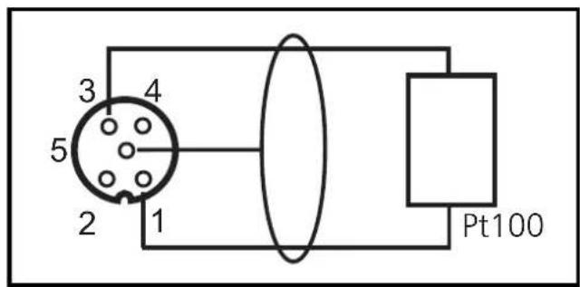
Connection of a 2-wire Pt100 element to the AS-i module
Analogue modul
Pin 1: S +
Pin 2: Al +
Pin 3: S -
Pin 4: Al -
Pin 5: screen (functional earth)
2-wire Pt100
Analogue modul
Pin 1: S +
Pin 2: Al +
Pin 3: S -
Pin 4: Al -
Pin 5: screen (functional earth)
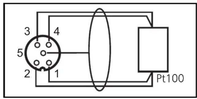
4-wire Pt100
4-wire Pt100 sensors supply more exact results than 2-wire sensors provided that the wire resistance is the same.
The changeover between 2- and 4-wire sensors is made via the parameter bit P3.
Important notes regarding Pt100 measurements:
In the Pt100 measurement principle, very low currents flow in the measuring electronics. It must be ensured that additional resistance (cables, contact and transition resistance, loose contacts, etc.) is avoided in the measuring circuit.
Only this way is a precise measurement, for which these modules are designed, possible.
In detail:
A 4-wire measurement always has to be preferred over a 2-wire measurement. In 2-wire measurement all transition and connection resistances add up and may massively falsify the measurement result.
Therefore a 2-wire measurement is not recommended!
High-quality plugs should be used for the AS-i AC2520 Pt100 module. Prewired and potted plugs with gold-plated contacts should be preferred.
Parameter setting of the analogue modules
| Parameter bit/ Designation | Description | Comments | ||||
| P0 filter | 1 50 Hz filter in the A/D converter active | The 50 Hz filter applies to the whole of Europe | ||||
| 0 60 Hz filter in the A/D converter active | ||||||
| P1, P2 periphery fault | Parameter bit | Periphery fault can be triggered by | ||||
| P1 P2 | 1 | 2 | 3 | 4 | ||
| 0 | 0 | on | off | off | off | |
| 0 | 1 | on | on | off | off | |
| 1 | 0 | on | on | on | off | |
| 1 | 1 | on | on | on | on | |
| P3 selection Pt100 elements | 1 | 2-wire mode | ||||
| 0 | 4-wire mode | |||||
Activation of the periphery fault message of the channels 1 to 4
According to the table above the parameter bits P1 and P2 are used to define which measuring channels can trigger a periphery fault message. But irrespective of the defined parameters all 4 channels are always transferred via the AS-Interface.
It is necessary to connect at least one Pt100 sensor before switching on the AS-i slave to start the A/D converter, otherwise the LEDs I1 to I4 flash at a frequency of about 5 Hz.
Operation
Check the safe functioning of the unit. Display by LEDs:
- LEDs yellow Al1 ... Al4 on: analogue signal in the measu
ring range
flashing: analogue signal outside the measuring range
-
LED green AS-i PWR on: AS-i voltage is applied
-
LED rot FAULT on: AS-i communication error
e.g. slave address 0
flashing: periphery fault *
- periphery fault
A periphery fault is indicated if at least one of the signals AI1, AI2, AI3 or AI4 is outside the measuring range or if nothing is connected to at least one analogue channel.
Measuring range of the Pt100 module
For the measuring ranges, the LED states and their meaning please see the following table:
| Range -200...850 °C | Units dec. | Units hex. | LED AI1...AI4 analogue | Meaning |
| < -219.4 °C | 32767 | 7FFF | flashes | short circuit |
| -219.4 °C... -200.1 °C | -2194 ... -2001 | F76E ... F82F on below nominal | range | |
| -200°C... +850 °C | -2000 ... 8500 | F830 ... 2134 | on | nominal range |
| 850.1 °C... 883.6 °C | 8501 ... 8836 | 2135 ... 2090 | on | above nominal range |
| >883.6 °C | 32767 | 7FFF | off | wire break |
Transmission time of the analogue values
The transmission time of the analogue values depends on the conversion time of the analogue signals into digital signals in the AS-i module and on the transmission time via the AS-Interface.
The conversion time for 4 Pt100 signals is 480~ms .
The transmission time of the 4 16-bit values via the AS-Interface ideally is 7 AS-i cycles per value. For a cycle time of 5 ms per AS-i cycle this results in a transmission time of 4 × 7 × 5 ms = 140 ms via the AS-Interface.
Thus the total transmission time for 4 temperature values ideally is 480ms (conversion time) +140ms (transmission time) = 620ms .
Brand : IFM
Model : AC2520
Category : Electronic module