
AL2410 - Electronic module IFM - Free user manual and instructions
Find the device manual for free AL2410 IFM in PDF.
| Product type | Electronic module for discrete inputs |
| Brand | IFM |
| Model | AL2410 |
| Number of discrete inputs | 4 (type 2 according to IEC 61131-2) |
| Sensor supply | 4 connectors, 100 mA per channel, 400 mA per group |
| Short-circuit protection | Per group of 4 channels |
| Communication | IO-Link (cyclic data, identification, short-circuit) |
| Supply voltage | 18...30 V DC via IO-Link port |
| Total required current | 550 mA (AL2410) |
| Max. cable length | < 30 m |
| Connection | M12 connector (IO-Link) and M8 sockets for sensors |
| Mounting | Flat surface, M4 screws, torque 1.2...1.5 Nm |
| Protection rating | IP67 (with protective caps) |
| Operating temperature | -25...70 °C (estimate) |
| Maintenance | No maintenance required |
Frequently Asked Questions - AL2410 IFM
User questions about AL2410 IFM
0 question about this device. Answer the ones you know or ask your own.
Ask a new question about this device
Download the instructions for your Electronic module in PDF format for free! Find your manual AL2410 - IFM and take your electronic device back in hand. On this page are published all the documents necessary for the use of your device. AL2410 by IFM.
USER MANUAL AL2410 IFM
1 Preliminary note 3
1.1 Symbols used 3
2 Safety instructions 3
3 Functions and features 3
4 Function 4
4.1 Communication, parameter setting, evaluation 4
4.1.1 IO-Link data 4
4.1.2 Visual indication 5
4.1.3 Parameter setting 5
4.2 Digital inputs 5
4.3 Sensor supply 5
5 Installation 6
6 Electrical connection 7
6.1 IO-Link connection 8
7 Pin connection 8
8 operating and display elements 8
9 Maintenance, repair and disposal 9
1 Preliminary note
Technical data, approvals, accessories and further information at www.ifm.com.
1.1 Symbols used
Instructions
Reaction, result
Cross-reference

Important note
Non-compliance may result in malfunction or interference.

Information
Supplementary note.
2 Safety instructions
- Read this document before setting up the product and keep it during the entire service life.
- The product must be suitable for the corresponding applications and environmental conditions without any restrictions.
- Only use the product for its intended purpose ( Functions and features).
- If the operating instructions or the technical data are not adhered to, personal injury and/or damage to property may occur.
- The manufacturer assumes no liability or warranty for any consequences caused by tampering with the product or incorrect use by the operator.
- Installation, electrical connection, set-up, operation and maintenance of the unit must be carried out by qualified personnel authorised by the machine operator.
- Protect units and cables against damage.
3 Functions and features
The device transmits the input states of the digital type 2 inputs and the status of the sensor supply to IO-Link.
4 Function
4.1 Communication, parameter setting, evaluation
4.1.1 IO-Link data
The device
- transmits the current states of the digital inputs cyclically in byte 0. Byte 1 is not used and always transfers the value '0'.
- transmits the device information "short circuit" (SC) cyclically in byte 2.
- transmits the equipment identification cyclically in byte 3.
- provides the equipment identification for writing acyclically (index 688, sub-index 0).
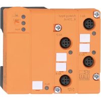
AL2410 (4 DI)
| Bit no. 7 6 5 4 3 2 1 0 | |||||||
| Byte no. 0 | |||||||
| Assignment 0 0 0 0 X1 3 X1.2 X1 .1 X1.0 | |||||||
| Byte no. 1 | |||||||
| Assignment 0 0 0 0 0 0 0 | |||||||
| Byte no. 2 | |||||||
| Assignment 0 0 0 0 0 0 K S1 | |||||||
| Byte no. 3 | |||||||
| Assignment Equipment identification | |||||||
For AL2410 the data bits 4...7 of byte 0 are transmitted with '0'.
AL2411 (8 DI)
| Bit no. 7 6 5 4 3 2 1 0 | ||||||||
| Byte no. 0 | ||||||||
| Assignment | X1.7 | X1.6 | X1.5 | X1.4 | X1.3 | X1.2 | X1.1 | X1.0 |
| Byte no. 1 | ||||||||
| Assignment | 0 0 0 0 0 | 0 0 | ||||||
| Byte no. 2 | ||||||||
| Assignment 0 | 0 0 0 0 | KS2 KS1 | ||||||
| Byte no. 3 | ||||||||
| Assignment Equipment identification | ||||||||
4.1.2 Visual indication
The device
- indicates the current state of an input (yellow LED).
- indicates a correct operation (green PWR/FLT LED lights).
- indicates a short circuit of one or several sensor supplies (red PWR/FLT LED lights).
4.1.3 Parameter setting
Device-specific parameter lists for IO-Link parameter setting are available
www.ifm.com
4.2 Digital inputs
Depending on the version the device has 4 (AL2410) or 8 (AL2411) digital inputs (type 2 input to IEC 61131-2). All inputs refer to the sensor supply potential.
4.3 Sensor supply
Depending on the version the device has 4 (AL2410) or 8 (AL2411) process connections on the front panel. Each process connection has a sensor supply rated for a nominal current of 100mA .
The short-circuit protection applies to a group of 4 inputs
- group 1: inputs X1.0...X1.3
- group 2: inputs X1.4 - X1.7 (only AL2411)
and is rated for 400mA per group.
So the total current of the group of 4 inputs can be taken from one of the process connections of the corresponding group.

Maximum cable length < 30 m .
A short circuit or overload has no effect on the sensor supply of the other group (only AL2411). Moreover every sensor supply has a short-circuit and overload
detection which is indicated by the red PWR/FLT LED and via the IO-Link interface.
A correct operation is indicated by the green PWR/FLT LED. The output voltage of the sensor supply is in linear proportion to the input voltage (positive supply cable of the IO-Link port). Voltage can vary within the IO-Link specification (18...30 V).
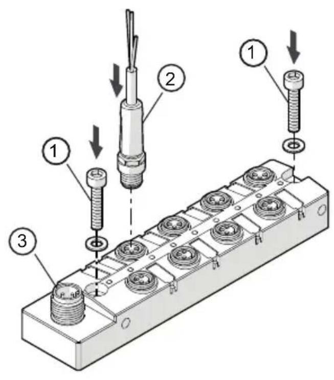
5 Installation

Disconnect power before installation.

For installation choose a flat mounting surface. The entire bottom of the module must lie flat on the mounting surface.
-
Fasten the module onto the mounting surface using M4 screws and washers (1). Tightening torque 1.2...1.5 Nm. Connect the plugs of the sensors to the M8 sockets.
-
Tighten firmly, recommended tightening torque 0.3...0.5 Nm.

As an alternative the module can be mounted laterally using two M4 screws, tightening torque max. 1 Nm.
To ensure the protection rating
- Cover the unused sockets with the enclosed protective caps. Tighten firmly, recommended tightening torque 0.3...0.5 Nm.
UK
1: M4 screws and washers (not supplied with the device). Tightening torque 1.2...1.5 Nm.
2: M8 connector
3: M12 connector IO-Link (X1)

Observe the maximum tightening torque of the connection cable.
6 Electrical connection

The unit must be connected by a qualified electrician.
The national and international regulations for the installation of electrical equipment must be adhered to.

Intended for connection to class 2 (cULus class 2) circuits only.
Disconnect power.
Connect M12 plug (IO-Link) to the M12 socket. Tightening torque 0.6...0.8Nm.
Connect the device.
6.1 IO-Link connection
The IO-Link port must be connected according to the IO-Link specification.
The current required by the devices depends on the current load of the sensor supplies.
The total current (AL2410 = 550 mA and AL2411 = 1050 mA) must be provided by the connected IO-Link master.

If the positive supply cable is interrupted the device may be supplied via the IO-Link cable. This may lead to an unwanted system behaviour.
7 Pin connection
Inputs
1: Sensor supply +
3: Sensor supply -
4: Data input

M12 connector IO-Link (X1)
1: L+
2: not connected
3:L-
4: C/Q / I/O-Link

8 Operating and display elements
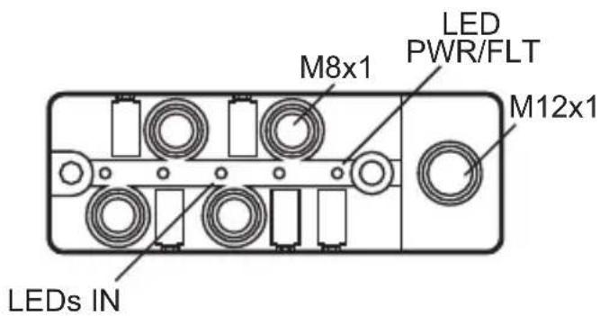
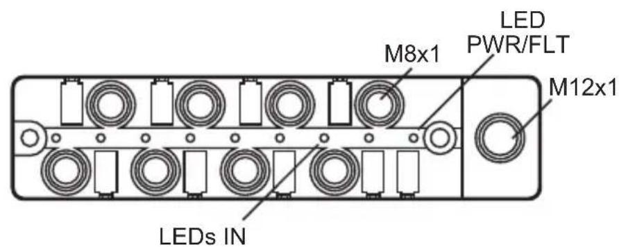
UK
Green LED PWR / FLT on: everything ok
Red LED PWR / FLT on: short circuit on one or several sensor supplies
LED PWR / FLT off: undervoltage or disconnected system
Yellow LED IN input on: input provides a type 2 HIGH signal
Yellow LED IN input off: input provides a type 2 LOW signal
9 Maintenance, repair and disposal
The operation of the unit is maintenance-free.
After use dispose of the unit in an environmentally friendly way in accordance with the applicable national regulations.
Contenu
6.1 Raccordement IO-Link 8
6.1 Raccordement IO-Link


- Preliminary note
- Symbols used
- Safety instructions
- Functions and features
- Function
- Communication, parameter setting, evaluation
- IO-Link data
- Visual indication
- Parameter setting
- Digital inputs
- Sensor supply
- Installation
- Electrical connection
- IO-Link connection
- Pin connection
- Inputs
- M12 connector IO-Link (X1)
- Operating and display elements
- Maintenance, repair and disposal
- Contenu
- Raccordement IO-Link
Brand : IFM
Model : AL2410
Category : Electronic module