
AC2057 - Industrial Automation IFM - Free user manual and instructions
Find the device manual for free AC2057 IFM in PDF.
| Product type | AirBox AS-i (Industrial Automation) |
| Brand | IFM |
| Model | AC2057 |
| AS-i Profile | S 3.F |
| Pneumatic valve type | 4/2 monostable |
| Power supply | Via AS-i network |
| Integrated sensor supply | 100 mA max per module |
| Compressed air pressure | 3 to 8 bar (max 8 bar) |
| Pneumatic connection | Legris 3000 / 8 mm |
| Sensor connection | M12 pluggable connector |
| AS-i connection | EMS wiring module |
| Addressing | 1 to 31, adjustable via addressing unit (delivery: address 0) |
| Manual override | Control screw (push/release or lock) |
| LED display | Green (AS-i voltage), yellow (inputs/outputs) |
| Electromagnetic compatibility (EMC) | EN 61000-4-2, contact discharge ±4 kV, air discharge ±8 kV |
| Protection against electrostatic discharge | Potential equalization, cable separation |
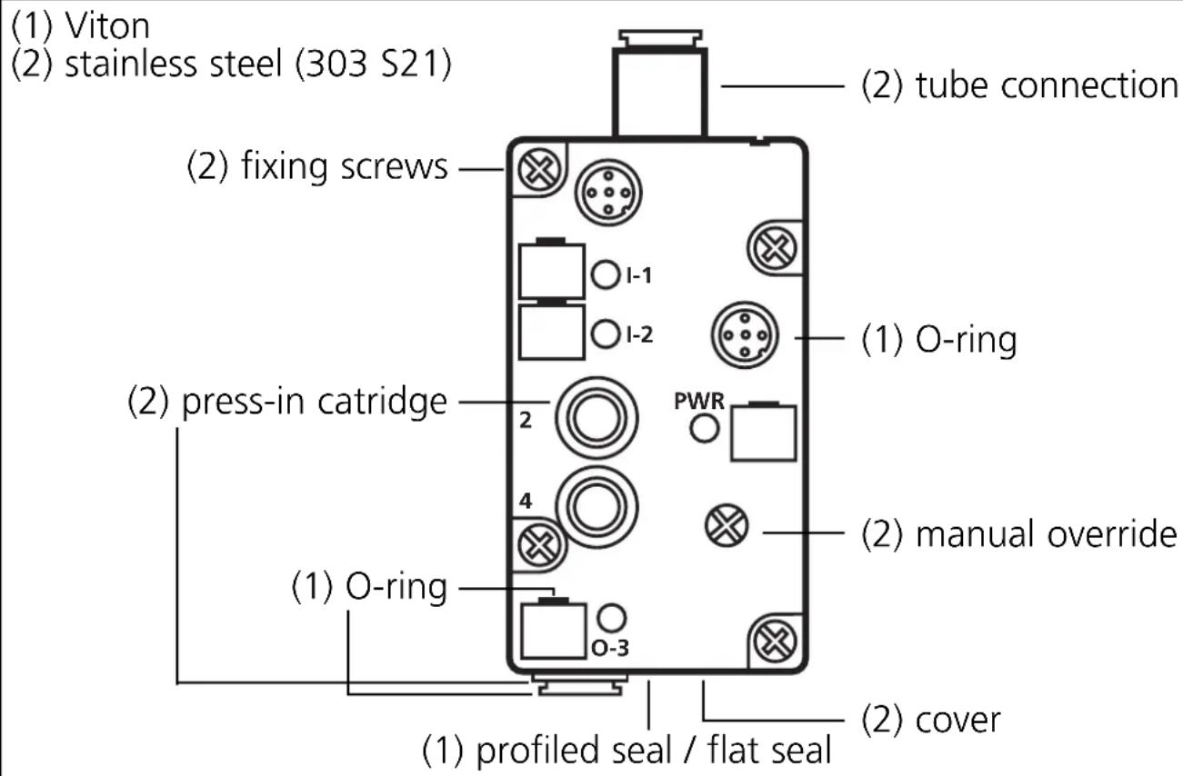
| Housing material | Stainless steel V2A |
| Compatible sensor types | 2-wire or 3-wire PNP switching (IEC 947-5-2) or mechanical switches |
| Number of logic inputs | 2 |
| Number of pneumatic outputs | 1 (4/2 valve) |
| Compressed air usage condition | Filtered air (5 µm), lubricated (ISO-VG10) or unlubricated |
| AS-i connection tightening torque | 0.8 Nm |
| Operating environment | Industrial |
Frequently Asked Questions - AC2057 IFM
User questions about AC2057 IFM
0 question about this device. Answer the ones you know or ask your own.
Ask a new question about this device
Download the instructions for your Industrial Automation in PDF format for free! Find your manual AC2057 - IFM and take your electronic device back in hand. On this page are published all the documents necessary for the use of your device. AC2057 by IFM.
USER MANUAL AC2057 IFM
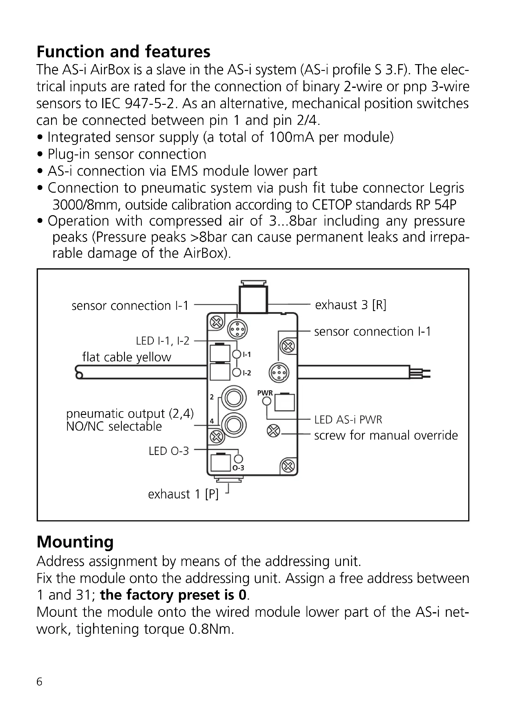
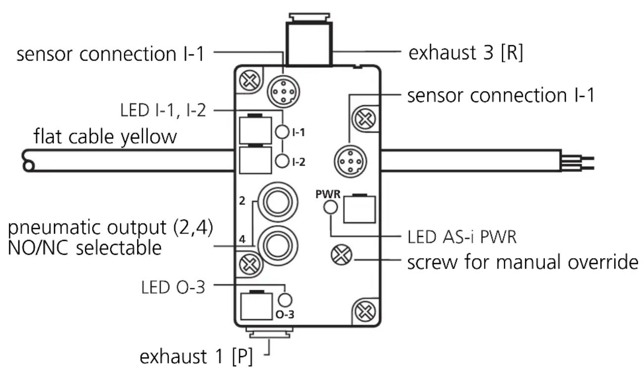
Function and features
The AS-i AirBox is a slave in the AS-i system (AS-i profile S 3.F). The electrical inputs are rated for the connection of binary 2-wire or pnp 3-wire sensors to IEC 947-5-2. As an alternative, mechanical position switches can be connected between pin 1 and pin 2/4.
- Integrated sensor supply (a total of 100mA per module)
- Plug-in sensor connection
- AS-i connection via EMS module lower part
- Connection to pneumatic system via push fit tube connector Legris 3000/8mm, outside calibration according to CETOP standards RP 54P
- Operation with compressed air of 3...8bar including any pressure peaks (Pressure peaks >8 bar can cause permanent leaks and irreparable damage of the AirBox).
Mounting
Address assignment by means of the addressing unit.
Fix the module onto the addressing unit. Assign a free address between 1 and 31; the factory preset is 0.
Mount the module onto the wired module lower part of the AS-i network, tightening torque 0.8Nm.
Materials
Compressed air
Adhere to the safety regulations and provisions for the installation of pneumatic systems. Switch off pressure.
Connect the compressed air supply 1 (P), the pneumatic output (NO/NC selectable) 2 and 4 and, if necessary, the exhaust 3 (R) to the pneumatic system. Cut the connection tube straight and push it into the tube fitting until you can feel the tube latch.
Removal of the tubes
To remove the tubes, push the black ring and pull out the tube at the same time.
Manual override
The pneumatic output (NO/NC selectable) can be activated manually by means of the screw for the manual override (pressing/releasing or pressing/turning/locking).
Electromagnetic compatibility (EMC):
The AirBox is rated for operation in industrial environments. The test of the electrostatic discharge was carried out in accordance with EN 61000-4-2 with the following test levels:
- Contact discharge ± 4kV
- air discharge ± 8kV
Special applications such as the conveying and distribution of bulk material can generate higher electrostatic charges.
To avoid electrostatic discharge the following remedial actions are possible, among others:
- Equalisation of potential according to the installation instructions
-
Separate laying of
-
signal and bus cables
- equipotential bonding conductors
-
power cables
-
physical separation of the AirBox and all cables from all parts carrying or discharging electrostatic charges
If these discharges are not avoided there is the danger of:
- injury to/incapacitation of operators and maintenance staff
- spark formation
damage to the AirBox - damage to the electrical equipment
The electrical triggering has priority over the mechanical triggering.
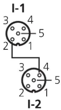
| M12 socket | I-1/PIN | I-2/PIN |
| sensor supply L+ | 1 | 1 |
| sensor supply L- | 3 | 3 |
| data input I | 4 | — |
| data input II | 2 | 4 |
| not used | 5 | 2+5 |
Assignment of the data bits
| Data bit | D0 D1 D2 D3 |
| Inputs / outputs | I-1 I-2 O-3 |
Operation
Check the safe functioning of the unit. Display by LEDs:
- LED green: supply voltage via the AS-i system
- LEDs yellow: external voltage supply
For trouble-free operation sufficiently treated air must be used (filtered air 5 m , lubricated (ISO-VG10)1) or not lubricated). Once the AirBox has been operated with lubricated air, it always has to be operated with lubricated air as the oil removes the initial lubrication.
1) You can find further notes on compressed air and EMC/ESD for the AirBox at www.ifm-electronic.com. Enter the article number of your AirBox on the start page under "Data sheet direct". You receive the additional product information by clicking on "Additional data".
Brand : IFM
Model : AC2057
Category : Industrial Automation