
AC5210 - Electronic module IFM - Free user manual and instructions
Find the device manual for free AC5210 IFM in PDF.
| Product type | AS-interface electronic module |
| Brand | IFM |
| Model | AC5210 |
| AS-interface version | 3.0 (downward compatible) |
| Number of inputs | 8 (2 x 4 inputs, two independent A/B slaves) |
| Maximum modules per master | 31 |
| Addressing | Via AC1144 addressing unit, integrated interface on the front |
| LED indicators | 1 x yellow (switched input), 1 x green (PWR), 1 x red (FAULT) |
| Connection | 8 M12 sockets |
| Power supply | Via AS-i flat cable |
| Protection rating | IP67 (with protective caps on unused sockets) |
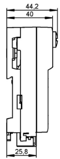
| Dimensions (L x l x H) | 44,2 x 40 x 25,8 mm |
| Mounting | On profile, adjustable flat cable orientation (3 positions) |
| Maintenance and cleaning | Avoid dust deposits on the base and upper part; check the locking mechanism |
| Spare parts and accessories | Protective caps E73004, sealing gasket E70413, addressing cable E70213 |
| Safety | Use protective caps to maintain IP67; tightening torque 0,6-0,8 Nm for M12 connectors |
| Repairability | Not specified; module designed to be replaced |
Frequently Asked Questions - AC5210 IFM
User questions about AC5210 IFM
0 question about this device. Answer the ones you know or ask your own.
Ask a new question about this device
Download the instructions for your Electronic module in PDF format for free! Find your manual AC5210 - IFM and take your electronic device back in hand. On this page are published all the documents necessary for the use of your device. AC5210 by IFM.
USER MANUAL AC5210 IFM
natural_image
3D rendering of a mechanical component with multiple circular ports and a handle (no text or symbols visible)Function and features
- maximum number of modules per master: 31 (2 independent A/B slaves per module)
• AS-interface version 3.0, downward compatible
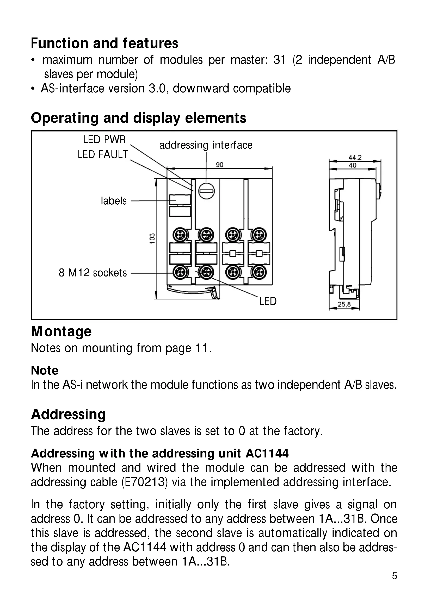
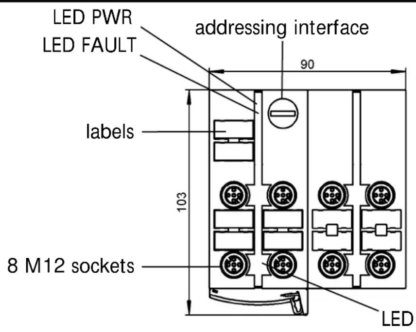
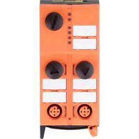
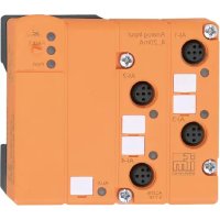
Operating and display elements
Montage
Notes on mounting from page 11.
Note
In the AS-i network the module functions as two independent A/B slaves.
Addressing
The address for the two slaves is set to 0 at the factory.
Addressing with the addressing unit AC1144
When mounted and wired the module can be addressed with the addressing cable (E70213) via the implemented addressing interface.
In the factory setting, initially only the first slave gives a signal on address 0. It can be addressed to any address between 1A...31B. Once this slave is addressed, the second slave is automatically indicated on the display of the AC1144 with address 0 and can then also be addressed to any address between 1A...31B.
Important:
Both slaves can be assigned any A/B addresses (e.g. 3A/6A or 9A/25B etc.). No address can be assigned doubly (e.g. 3A/3A or 9B/9B etc.).
Restore the factory setting (address both slaves to 0)
Using the addressing unit AC1144 the factory setting of the module is restored by writing a 0 to ID1 of the second slave (factory setting ID1 = 2) by the internal software.
If a slave with the ID code "A" (option of extended addressing mode) is connected to a master of the first generation (version 2.0), the parameter P3 must be 1 and the output bit D3 = 0*. The output bit D3 must not be used. * default setting
If a slave with the ID code "A" (option of extended addressing mode) is connected to a master of the first generation (version 2.0), an address between 1A and 31A must be assigned to this slave.
AC5210
8 inputs / AS-i profile 2x S-0.A.E / extended addressing mode: yes
| Data bit D0 D1 D2 D3 | |||
| Input 1 2 3 4 | |||
| Socket I-1/2 I-1/2 I-2 I-3/4 I-3/4 I-4 |
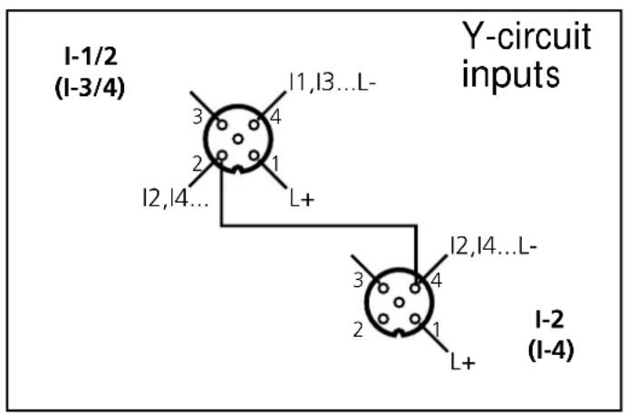
Electrical connection
Connect the plugs of the sensors to the M12 sockets. To ensure the protection rating IP 67 you must
• cover the unused sockets with protective caps (E73004) ^* , tightening torque 0.6...0.8 Nm.
- use the flat cable end seal (E70413)* if the module is at the end of the cable line.
*) to be ordered separately
Operation

Avoid build-up of dirt and dust on the upper and lower parts so that the locking mechanism is not affected.
Check the safe functioning of the unit. LED display:
• LED yellow: inputswitched
• LED PWR green: AS-i voltage supply o.k.
- LED FAULT red is lit: AS-i communication error, slave does not participate in the "normal" exchange of data, e.g. slave address 0
- LED FAULT red flashes: peripheral fault, e.g. sensor supply overloaded or shorted

Overload and short circuit of the input supply are signalled as peripheral fault to the AS-i master (version 2.1 or higher).
Technical data
You can download the data sheet from our website at www.ifm-electronic.com if required.
natural_image
3D mechanical assembly diagram showing a bracket with directional arrows indicating movement or force (no text or symbols present)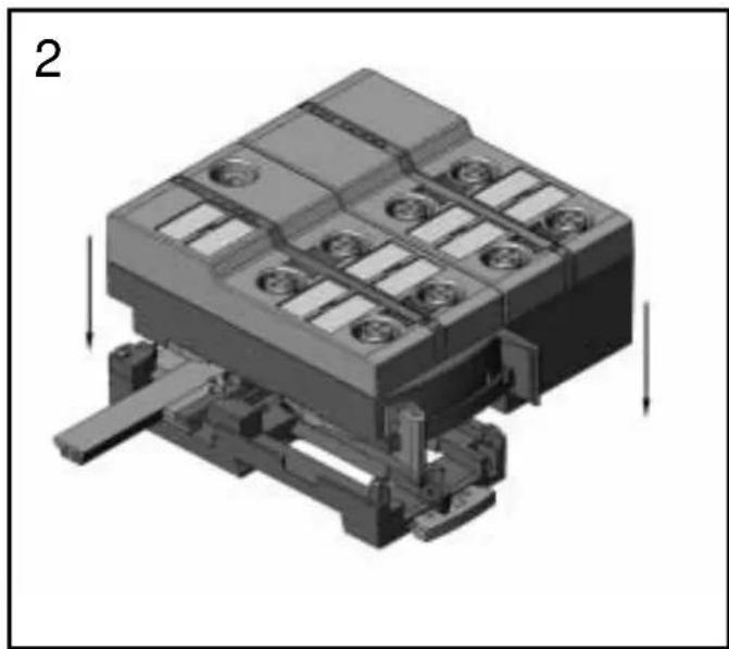
natural_image
3D mechanical assembly diagram showing a housing with mounting holes and a base mount (no text or symbols)Orientation of the flat cable on delivery
Carefully place the yellow flat cable into the profile slot.
Mount the upper part.
natural_image
3D rendering of a mechanical or electronic component with multiple slots and a handle, no visible text or symbols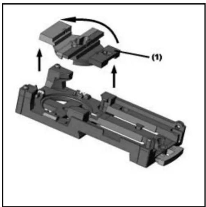
natural_image
3D mechanical assembly diagram showing a bracket with mounting holes and a component labeled (1), no readable text or symbols present.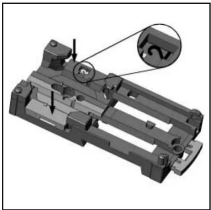
natural_image
3D mechanical part diagram showing internal components and a close-up of a circular feature labeled '12' (no text or symbols beyond the label)With the supplied lower part the flat cable can be aligned in three directions.
For the requested direction place the flat cable guide (1) accordingly.
Settings at the lower part
Select the position 1, 2 or 3 depending on the requested flat cable alignment ( ).
A = Factory setting
natural_image
3D mechanical assembly diagram showing internal components and a shaft (no text or symbols)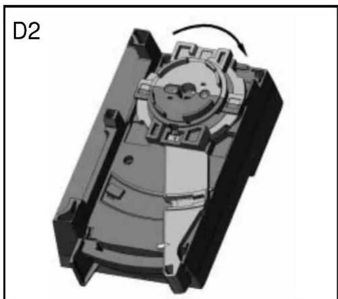
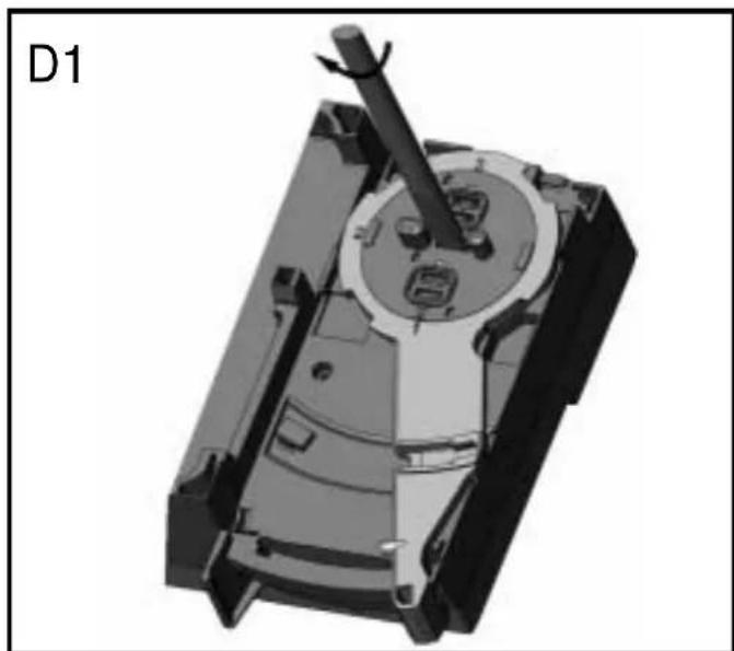
natural_image
3D mechanical component diagram showing internal structure with rotation arrow (no text or symbols)Settings at the upper part
Then set the selected position at the upper part. To do so, turn the arrow to the corresponding number (figure D1 and D2).
Use a tool, e.g. a screwdriver (figure D1) or the yellow / black flat cable guide (figure D2).
natural_image
3D mechanical component with multiple ports and a lever mechanism (no visible text or symbols)Open the unit using a tool as shown (e.g. screwdriver).
natural_image
3D rendering of a mechanical component with multiple ports and a lever, no visible text or symbols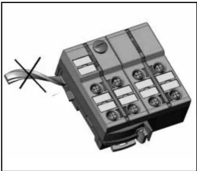
natural_image
3D rendering of a rectangular electronic component with multiple ports and a cable, no visible text or symbolsTake care in laying the AS-i flat cable, the flat cable should be laid straight for about 15 cm.
- Function and features
- Operating and display elements
- Montage
- Note
- Addressing
- Addressing with the addressing unit AC1144
- Important:
- Restore the factory setting (address both slaves to 0)
- AC5210
- Electrical connection
- Operation
- Technical data
- Orientation of the flat cable on delivery
- Settings at the lower part
- Settings at the upper part
Brand : IFM
Model : AC5210
Category : Electronic module