IF5888 - Inductive sensor IFM - Free user manual and instructions
Find the device manual for free IF5888 IFM in PDF.
User questions about IF5888 IFM
0 question about this device. Answer the ones you know or ask your own.
Ask a new question about this device
Download the instructions for your Inductive sensor in PDF format for free! Find your manual IF5888 - IFM and take your electronic device back in hand. On this page are published all the documents necessary for the use of your device. IF5888 by IFM.
USER MANUAL IF5888 IFM
Installation Instructions
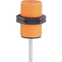
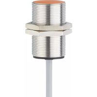
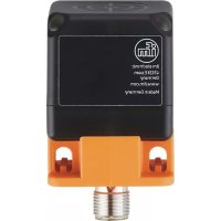
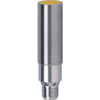
Inductive sensor
DC / unipolar
Notice de Montage
Détecteur inductif
DC / non polarisé
取扱説明書
高周波誘導式近接スイッチ
直流2線式/無極性型
efector100

人体の保護を目的とした安全回
路に組込むことを禁止します。

text_image
6 DC DC DCtext_image
n7 R C DCFunction and features
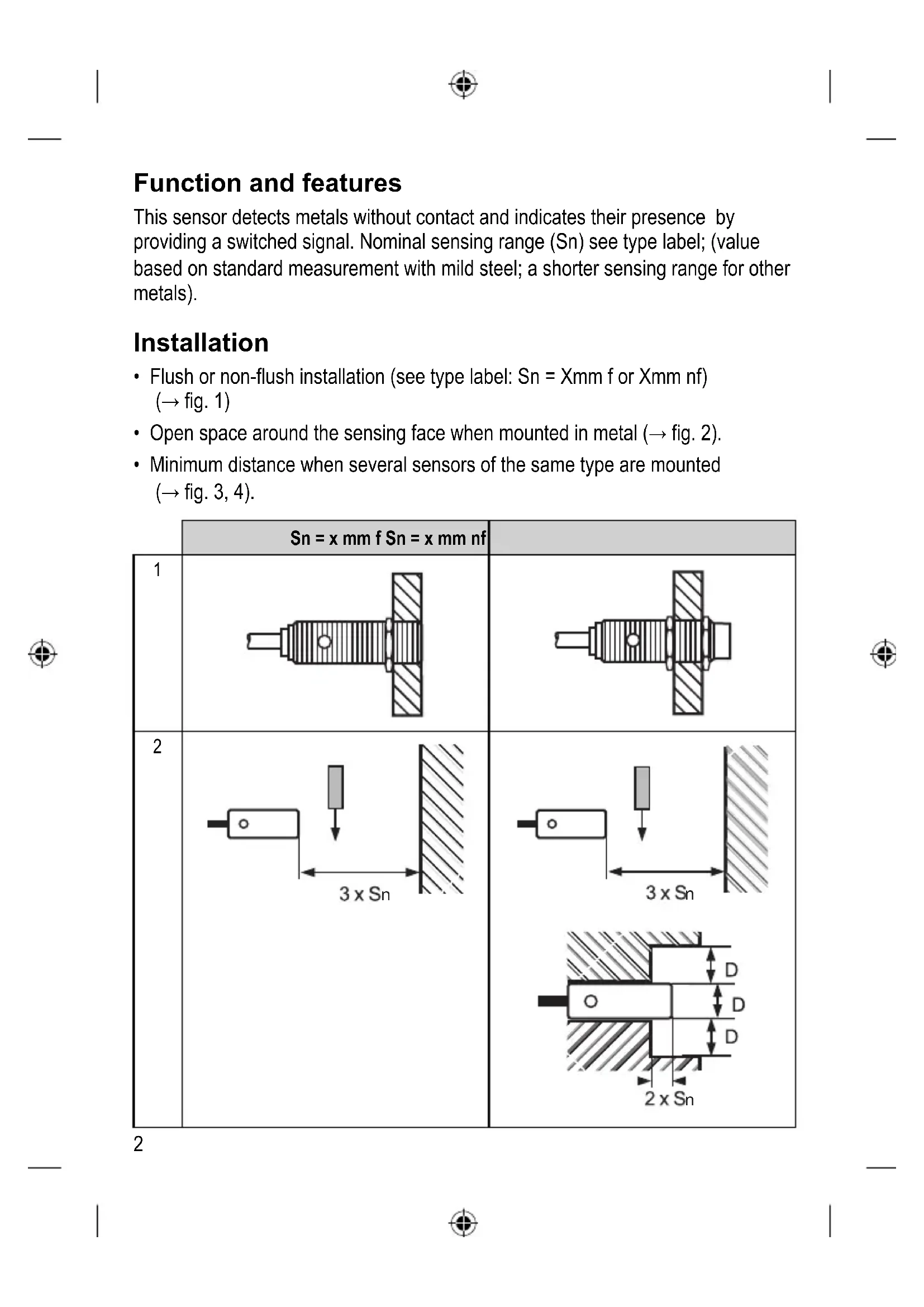
This sensor detects metals without contact and indicates their presence by providing a switched signal. Nominal sensing range (Sn) see type label; (value based on standard measurement with mild steel; a shorter sensing range for other metals).
Installation
- Flush or non-flush installation (see type label: Sn = Xmm f or Xmm nf) (→ fig. 1)
- Open space around the sensing face when mounted in metal (→ fig. 2).
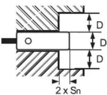
- Minimum distance when several sensors of the same type are mounted ( fig. 3, 4).
| Sn = x mm f Sn = x mm nf | ||
| 1 | 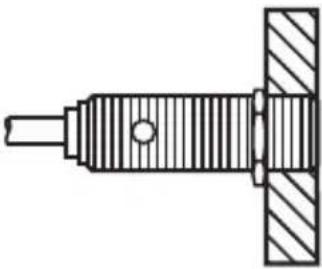 | 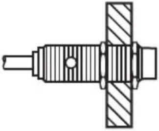 |
| 2 | 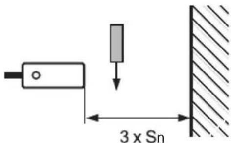 | 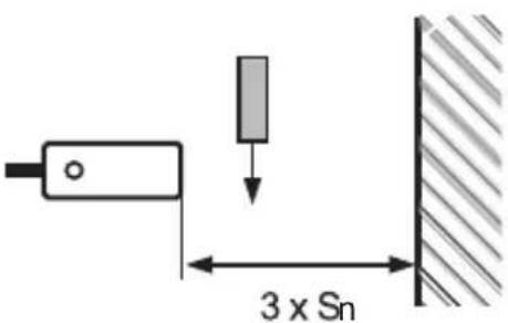 |
 | ||
| 3 | 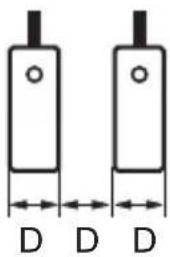 | 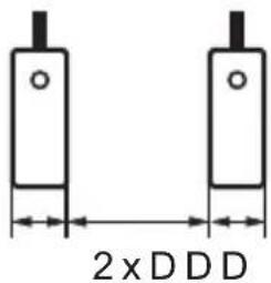 |
| 4 | 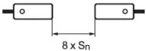 | 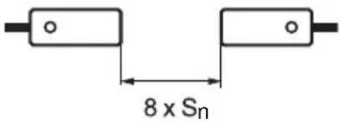 |
Electrical connection
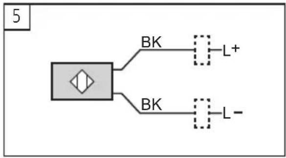
▶ Disconnect power before connecting the proximity switch; connection: → fig. 5).
flowchart
graph TD
    A["Block with diamond shape"] --> B["BK"]
    A --> C["BK"]
    B --> D["L+"]
    C --> E["L-"]
- For cables longer than 30 ~m and wires greater than 0.5 ~mm^2 the cable should be laid separately from sources of interference (at a distance of about 50 ~cm ) or a screened cable should be used.
- Connect the load before applying the operating voltage.
- Observe the values for current rating and minimum load current.
- If capacitive loads are used, ensure that the peak current rating is not exceeded.
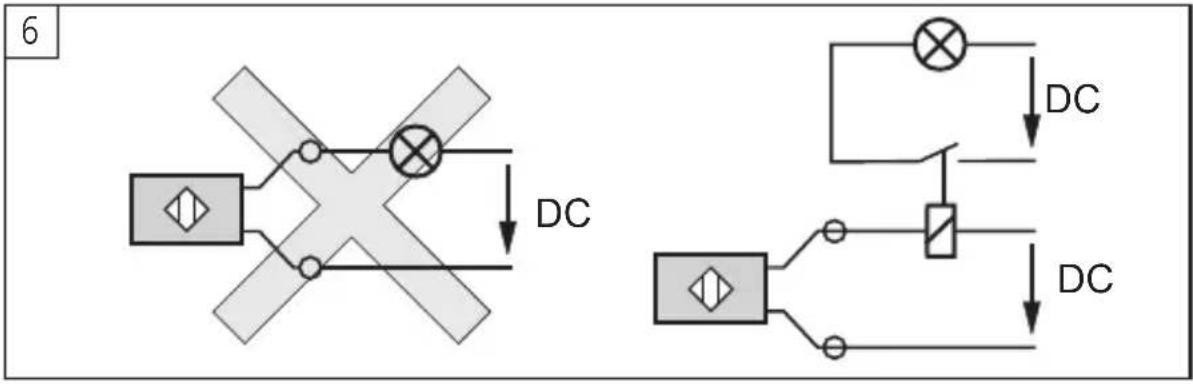
▶ Do not connect loads of low resistance (e.g. lamps) directly to the sensor. Switch these loads via a relay ( fig. 6):
text_image
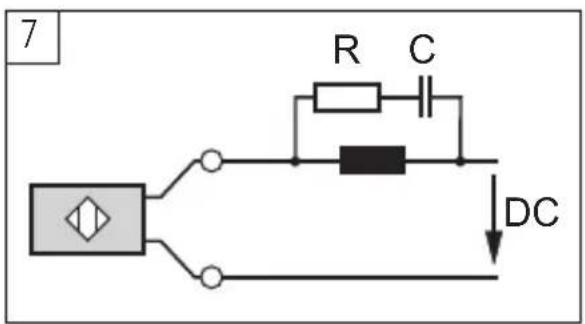
6 DC DC DC▶ For inductive loads a RC circuit should be connected in parallel to the load ( fig. 7).
text_image
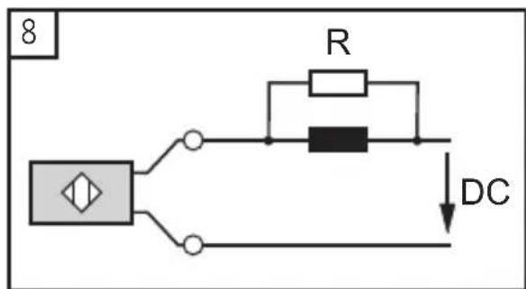
7 R C DC▶ A load which is too low for 2-wire sensors may lead to malfunction. In such a case a resistor should be connected in parallel to the load ( fig. 8).
text_image
8 R DC- For series connection consider the voltage drop of each unit.
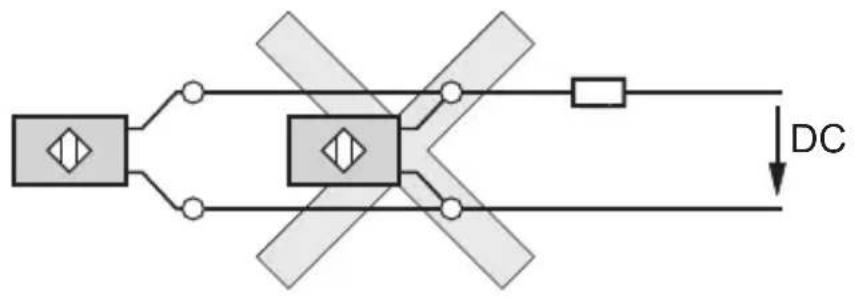
▶ As a rule avoid connecting 2-wire units in parallel (only in exceptional cases, check the safe function, → fig. 9):
9
flowchart
graph TD
    A["Input"] --> B{Switch}
    B --> C["DC"]
    B --> D["Output"]
    style A fill:#ccc,stroke:#333
    style D fill:#ccc,stroke:#333
    style B stroke-dasharray: 5 5
UK
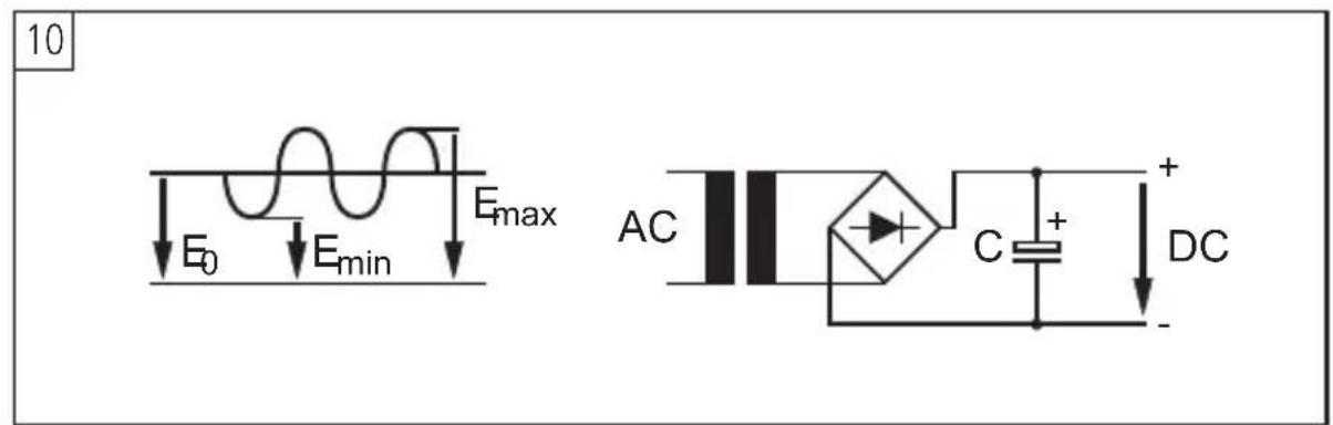
The supply voltage must correspond to the values indicated on the label. If it is not stabilised, a capacitor should be connected (at 24 V and 1 A for example a capacitor of 1000 μF, 50 WV → fig. 10):
10
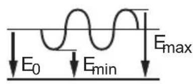
text_image
E₀ Eₘᵢₙ Eₘₐₓ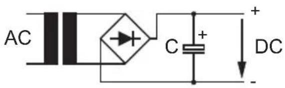
text_image
AC C + DC
flowchart
graph TD
    A["Block"] -->|BK| B["L+"]
    A -->|BK| C["L-"]
text_image
6 DC DC DCtext_image
6 DC DC DC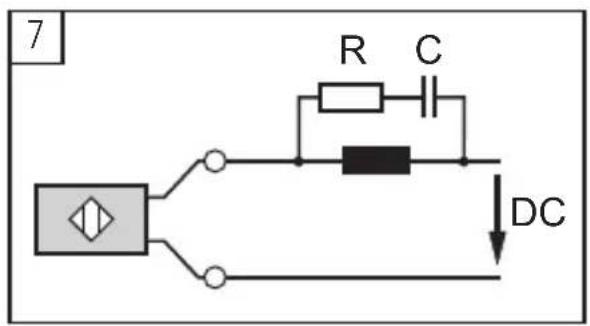
text_image
7 R C DC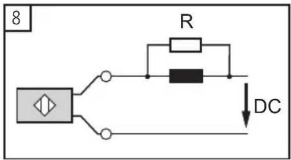
text_image
8 R DC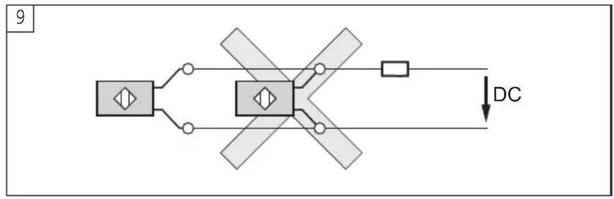
flowchart
graph TD
    A["Device"] --> B["Switch"]
    B --> C["DC"]
    style A fill:#f9f,stroke:#333
    style C fill:#ccf,stroke:#333
text_image
10 E₀ Eₘᵢₙ Eₘₐₓ AC C + DC + -
JP